Dorian Coves
-
Prototype Reveal: USB Micro-Ohmmeter for Sub-Milliohm Measurements
10/12/2025 at 14:06 • 0 commentsAfter a few teasers, here’s the first fully functional version of my USB micro-ohmmeter.
Originally designed to test contact resistances in EV charging connectors, it’s now proving to be a precise and repeatable measurement tool for shunts, cables, and low-resistance connectors of all kinds.
![]()
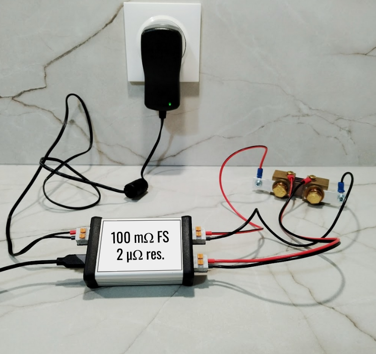
Photo of the prototype measuring a precision shunt (100 µΩ, 0.25%). Key Specs
- Measurement range: 0–100 mΩ (more to be tested)
- Resolution: < 2 µΩ
- Calibrated: Using precision resistors (100 µΩ, 1 mΩ, 10 mΩ)
- Interface: USB-C with SCPI command set
The first measurement results are even better than expected — especially in terms of stability and effective resolution.
For example, the ADC output shows about 88 counts when measuring a 100 µΩ shunt, which translates to an estimated resolution of ~1.14 µΩ.
Looking for Early Testers
I’m now looking for early testers interested in trying out this first version. If you work with low-resistance measurements and would like to give feedback on performance, usability, or possible improvements, please leave a comment or send me a message.
Your input will directly shape the next revision — which I plan to release later on Tindie.
What’s Next
In the next project log, I’ll run a stability analysis and share some thoughts on calibration methods for milliohm measurements.
-
The Open-Source Project Behind My Micro-Ohmmeter
08/28/2025 at 15:15 • 0 commentsBefore designing my own precision micro-ohmmeter, I started by studying an excellent open-source project by Dennis Vollrath, published in Servo Magazine:
https://www.servomagazine.com/magazine/article/build-a-simple-micro-ohmmeter
It’s a compact, well-thought-out DIY design with solid explanations — a perfect starting point for anyone exploring low-resistance measurements.
![]()
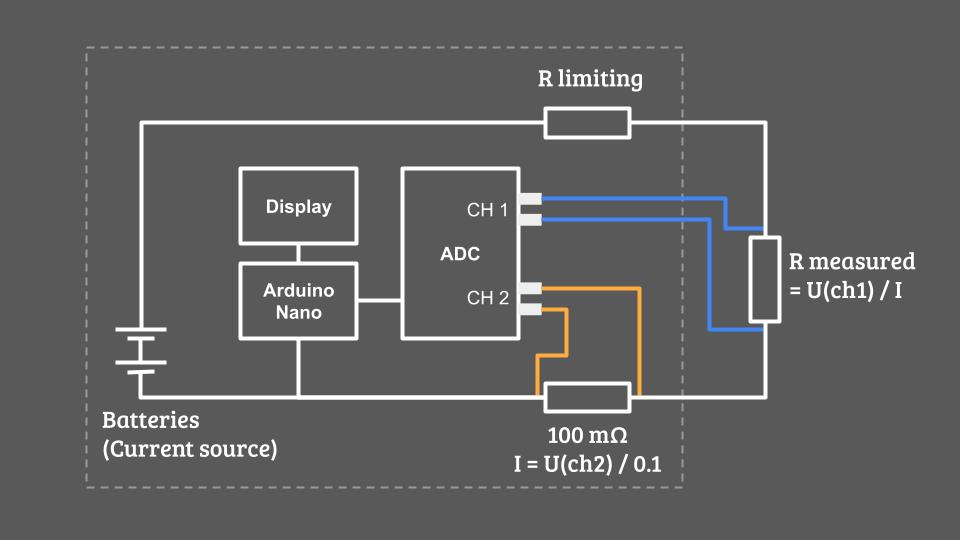
Simplified schematic of Dennis Vollrath’s design
What Makes Dennis’ Design Great
This project achieves surprisingly high performance for something you can build at home thank's to:
- High test current — around 1.2 A
- 18-bit ADC ENoB ! (17 bits in unipolar mode)
- Programmable differential amplifier with gain up to ×8 (in the ADC)
That translates into an estimated measurement resolution of:
Resolution = ADC voltage step / Current = (0.256 / 2^17) / 1.2 = 1.6 µOhm
For a device you can build for under €50, that’s remarkably good — especially with such a short BOM and a straightforward assembly.
Why I Had to Go Further
While Dennis’s design is excellent for hobbyists, my goal was to build something industrial-grade for integration into automated test benches. That required several key changes:
1. Professional Hardware
I redesigned the PCB to meet professional manufacturing standards — compact, robust, and ready to fit inside a proper enclosure with DIN rail mounting and standard connectors.
2. Power Supply Upgrade
The original design used batteries and a 5 Ω resistor to limit the current (Power loss = R*I² = 7,2 W in heat). My version had to work directly from the client’s 24 V DC supply, so I redesigned the power stage to efficiently deliver a stable, high test current. I also added circuitry to pulse the current only during measurements to avoid unnecessary heating.
3. USB-Only Interface
Since the device is part of an automated test bench, it doesn’t need a screen. I switched to a USB-only interface and rewrote the firmware accordingly to communicate directly with the client’s software.
4. Improved Analog Front-End
I added analog filtering on the ADC inputs and carefully optimized the PCB layout to minimize crosstalk and noise pickup — critical when you’re measuring signals in the microvolt range.
5. Calibration for Accuracy
Finally, I wanted each unit to be factory-calibrated against precision reference resistors to guarantee performance and reproducibility. I’ll share more about the calibration process in an upcoming log.
What’s Next
Dennis Vollrath’s project was a fantastic foundation, and my version takes the concept further — from a DIY project to a precision lab instrument.
In the next log, I’ll unveil my custom micro-ohmmeter design — optimized for accuracy, reliability, and industrial integration.
Stay tuned!
-
Measuring Micro-Ohms: The Art of Fighting Physics
08/13/2025 at 11:02 • 0 commentsMeasuring small resistances value isn’t new to most engineers — but once you get down to the milli-ohm or micro-ohm range, small details start to dominate. Wiring and connectors can add more resistance than the part itself. Contact resistance can change between measurements. High test currents cause self-heating, altering the value you’re trying to capture. And even tiny temperature differences between metals can generate microvolts that mask your real signal.
The Main Challenges
- Parasitic Resistance Wires, connectors, PCB traces… …all add unwanted resistance.
- Self-Heating High current improves resolution, but even a few °C rise can cause a 1 % error.
- Noise & Resolution Limits Measuring 60 µΩ at 1 A means resolving 60 µV — far beyond the 10-bit ADC of an Arduino UNO.
- Thermoelectric Voltages
![]()
The Reliable Fix: 4-Wire Measurement
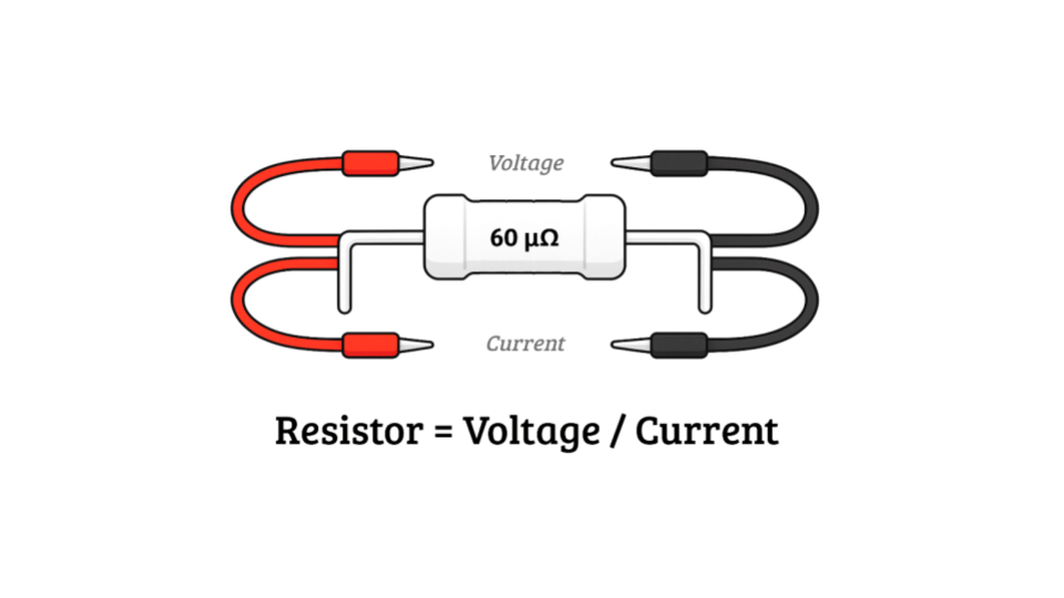
The only robust method is the Kelvin (4-wire) connection:
![]()
Two wires inject a known current through the resistor. Two separate wires measure the voltage drop.
This bypasses wiring resistance and lets you use a high-impedance voltmeter or precision ADC for clean readings.
Limit heating by applying current only during measurement. Your resolution will depend on voltmeter precision, range, and source current quality.
DIY 4-wire setup
![]()
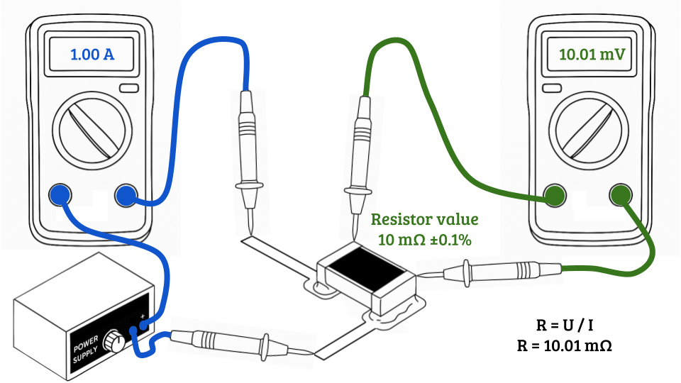
You can try this right now with:
- A power supply
- Two multimeters
- Four probes
One meter measures current, the other measures voltage. Simple, but dramatically more accurate than a 2-wire setup.
Measuring micro-ohms isn’t magic — it’s about eliminating every source of error.
In the next log, I’ll share the open-source design that inspired me to build my own compact, “low cost”, precision micro-ohmmeter.
-
Why Build a Micro-Ohmmeter?
07/30/2025 at 15:22 • 0 commentsThis whole project started with a phone call from a friend who designs custom industrial machines:
- Hey Dorian, I need to measure how the electrical resistance of automotive connectors changes as they get mated and unmated thousands of times. Is that something easy to do?
- Well… that depends on what resistance values we’re talking about.
- Around 60 micro-ohms.
- And what’s your budget?
- Under €1000 ... for the whole electronics part of the test bench... and everything has to fit in something the size of a shoebox.At that point, I couldn’t help but laugh.
When I started looking into it, I realized I couldn’t find any instrument that could:
- Resolve a few micro-ohms reliably,
- Connect to a PC over USB,
- Be compact and robust enough for industrial use,
- And still cost under €500 (most commercial units are well above €1000).
The closest solution I found was to cobble something together using a programmable lab power supply and a bench multimeter in a 4-wire setup, all controlled by a PC.
With decent Siglent gear that would have cost around:
- SDM3045X 4½-digit multimeter – €369 (excl. VAT)
- SPD1168X programmable power supply – €229 (excl. VAT)
So about €600 per measurement channel, and that’s just for the instruments — not exactly compact or budget-friendly.
And that’s when I decided to build my own tool.
In the next logs, I’ll dive into why measuring such low resistances is tricky, and show the open‑source design that kick‑started this project.
LysVolt MicroOhm - 4-wire precision ohmmeter
USB 4-wire micro-ohmmeter made in France for precise low-resistance measurements up to 100 mΩ with 2 µΩ resolution