 Olda
Olda
Magnetic Road Transport System for TT Scale Layout — DIY Control on ESP32
Autonomous road transport system for TT scale model railway layout. The goal is complete control of both rail and road traffic without DCC, built on ESP32, with maximum use of 3D printing. The purpose is to create a complex traffic simulation — traffic jams, intersection operations, bus transport with stops, realistic vehicle behavior.
Commercial road transport systems in model railways work on a guide-wire principle with fixed distances and constant speed. The result is almost comical — when one vehicle slows down in a curve, every vehicle behind it slows down too. That is not traffic, that is a parade. The goal of this project is to simulate traffic as it actually works — each vehicle decides independently, accelerates, brakes and reacts to the situation on the route regardless of the others.
Drive Principle
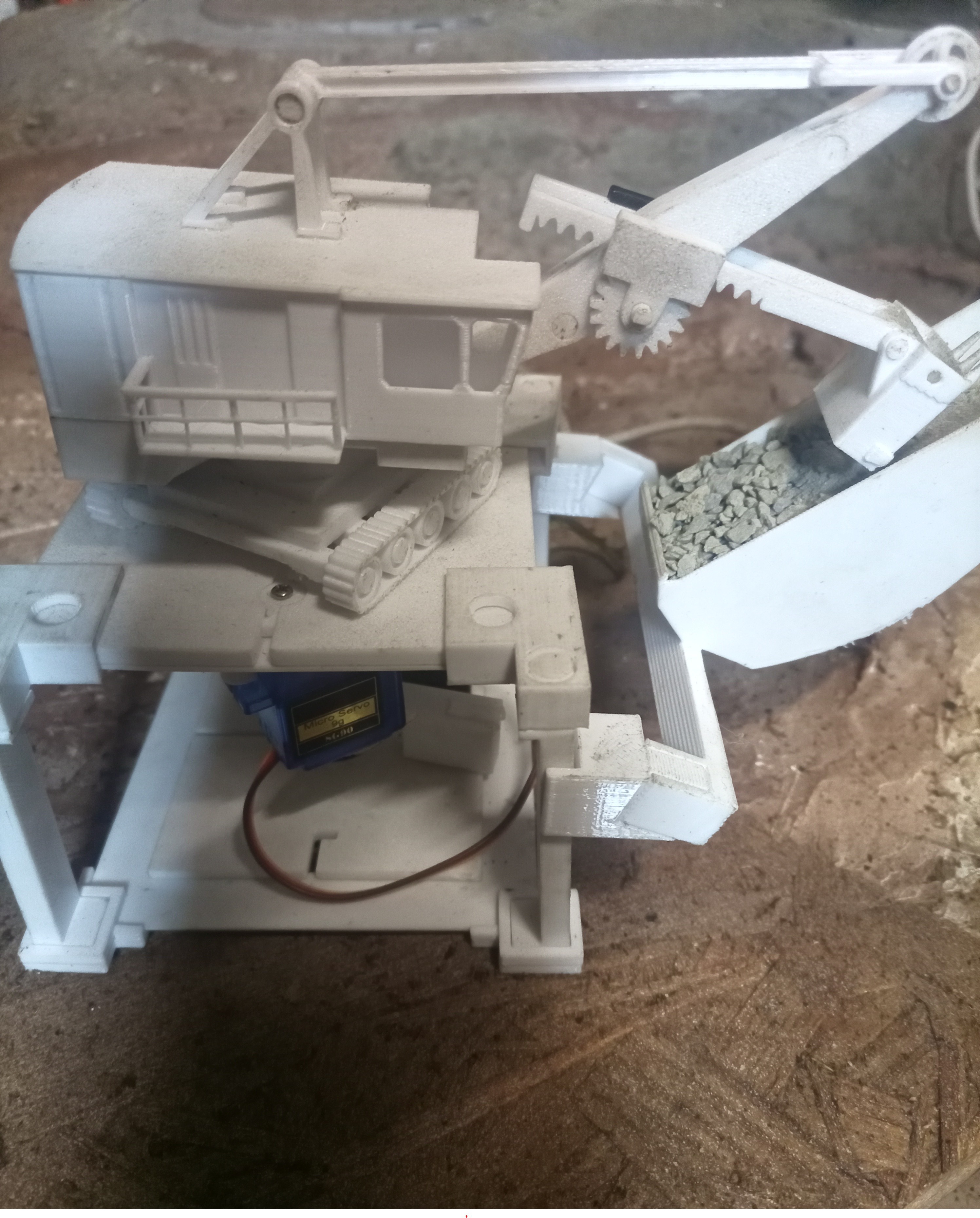
A hidden track runs beneath the road surface. A carriage with a DC motor, ESP32-C3 and neodymium magnets travels along this track. The magnets pull the vehicle model through the road surface. The model itself is hollow — no motor, no electronics inside. All drive and control is below the road. The overall control logic is identical to rail operations. In theory, DCC decoders and accessories can be used to control the magnetic carriages, so there is no need to abandon DCC control logic.
Control Architecture
Three layers:
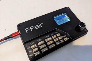
Slave — ESP32-C3 inside the carriage. Receives instructions, handles acceleration and braking ramps locally. Communication via ESP-NOW.
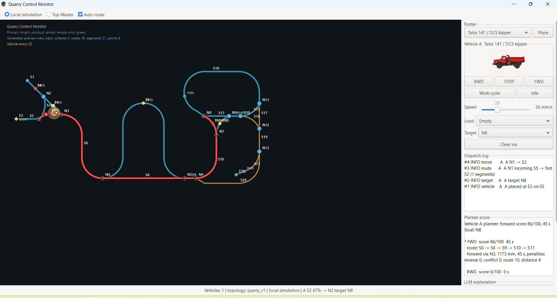
Master — ESP32-S3. Manages traffic rules — block occupancy, turnout and signal states, vehicle position based on hall sensors, timetable execution.
Top layer — software running on dedicated hardware. Builds and adjusts the timetable, responds to operational situations. When a delay occurs, it recalculates the entire schedule — rearranges crossings, adjusts priorities, generates announcements. Master executes, top layer decides.
If the top layer fails, the system continues operating at master level using the last valid timetable.
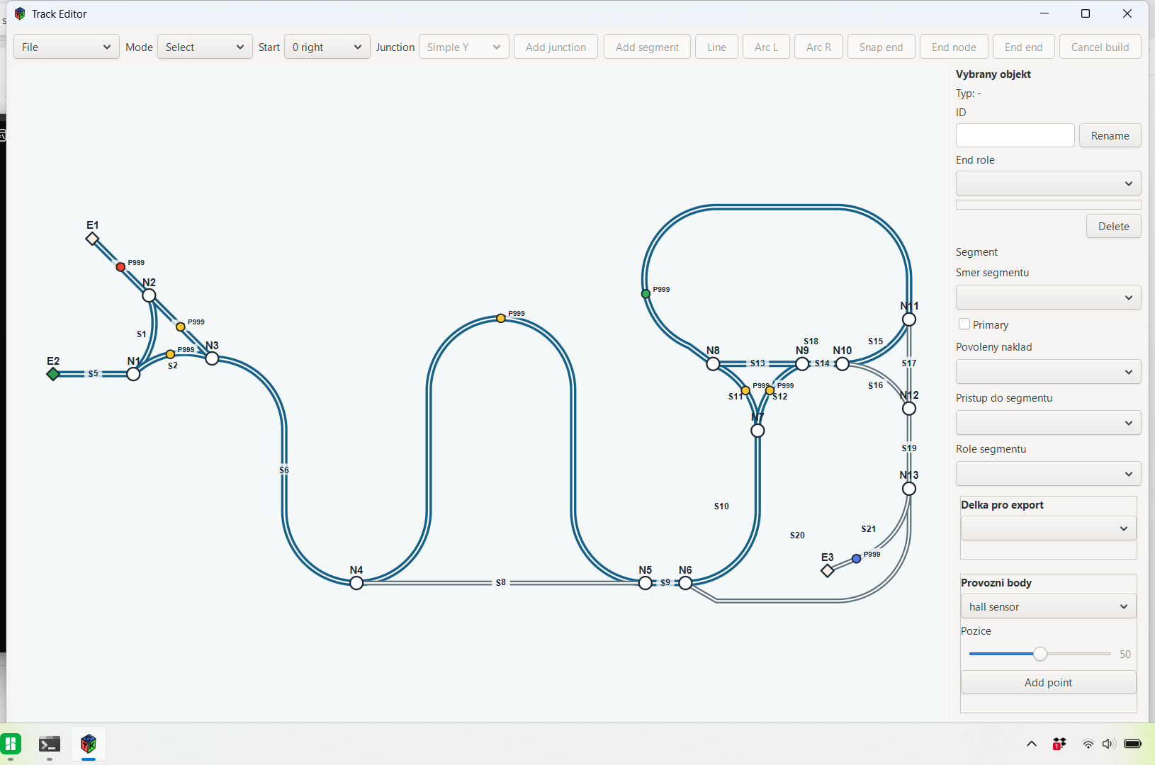
Test Polygon
Quarry — approximately two meters of road, switchbacks, Y junction. Purpose: verification of mechanics, electronics, control software and materials before building the full layout. Terrain is 3D printed.
Current state: manual control via buttons (FWD, BWD, STOP) and potentiometer for speed.
Target: three carriages in fully automatic operation overnight without intervention.

Why I Am Publishing This
I have been working on this for four years. After this long, I see things the way I am used to seeing them, not the way they are. I am looking for a fresh perspective on the mechanics, electronics and the overall approach.
 Arturo
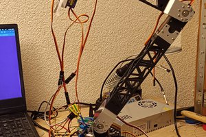
 Stanislav Britanishskii
 Silícios Lab
 Maximiliano Palay