My casio F91W needs a new CR2016 coin cell. Each cell runs the watch for ~7 years and uses a tiny amount of lithium, but I find single-use/disposable lithium offensive on a planet with so little of it.
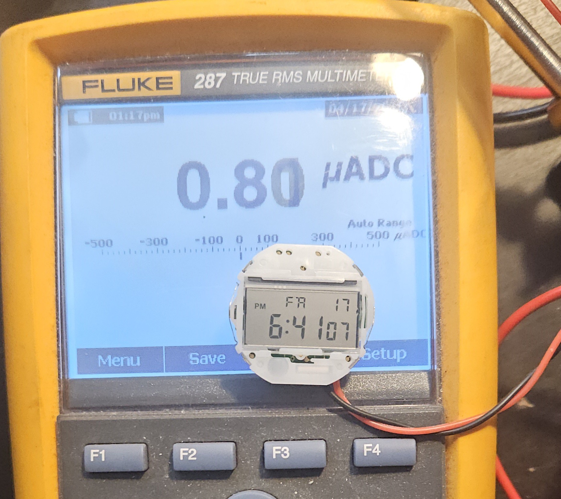
7 years to drain a 90mAh battery comes out to 1.5uA, but direct measurement shows an amazing range between 800nA and 350nA, or 2.5 to 1 uW. Gravity energy storage is laughably impractical for anything real, but it might actually work here!
A CR2016 stores about 800J, which is pretty impressive if you think about it: that could lift 82kg/180lbs by 1 meter/3ft. I don't have a machine shop, so I think I'll shoot for less energy per charge. I'll turn a crank once a week if it saves lithium.
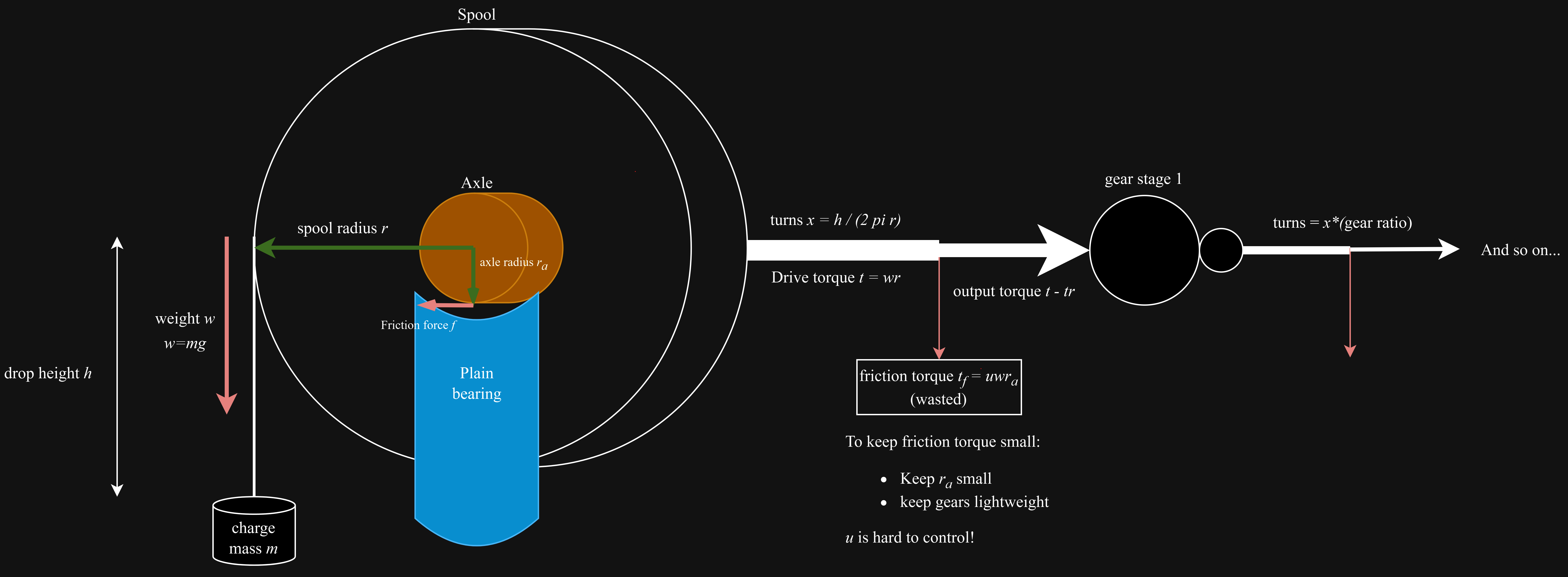
Plan: Suspend a few-kg weight about 1-2m from a string wrapped around a spool. The spool applies torque to a rotary generator through a gear train that provides a ratio big enough to accomplish a reasonable runtime. Generator output current provides opposing torque, slowing descent per load.
Each stage is subject to a holding torque set by the static friction of the bearing used. The friction force develops a torque with the arm length set by the radius of the axle.
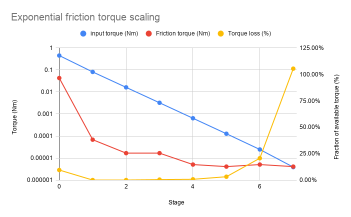
In the first few stages, this torque is negligible. But as the gear ratio increases from stage to stage, a sizeable input torque quickly scales down to a few microNm, even the tiny friction seen in a ball bearing supporting a few grams can become too great:
This model doesn't include the gear teeth themselves, so it's probably much worse than this, but this illustrates the problem pretty well.
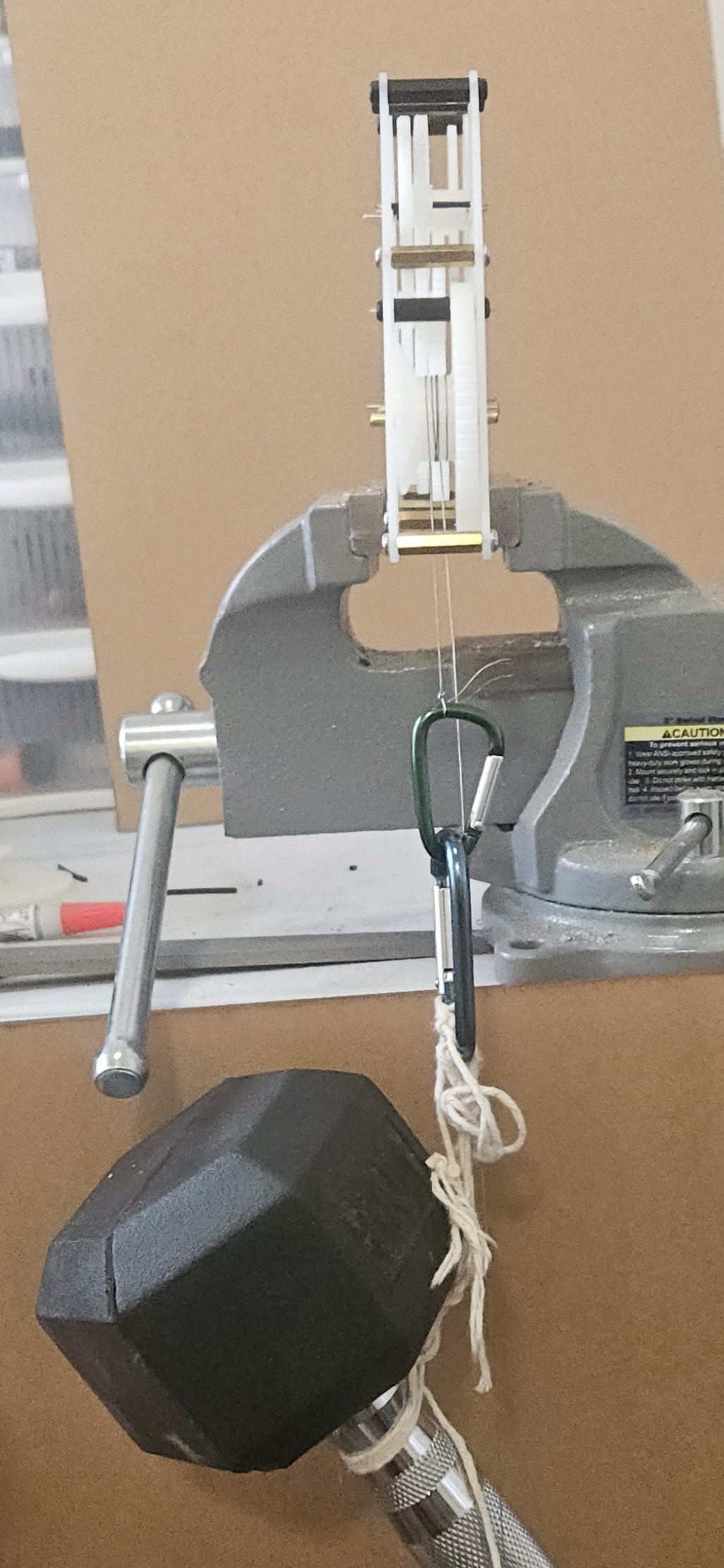
Currently I cannot seem to turn the 7th stage with the heaviest weight I can support (10lb) and the widest spool I can accommodate, 20mm. I may need to drop the last stage!
I'm using a spur gear generator feature; I can't figure out how to link to it here but of the couple I've tried this is my favorite.
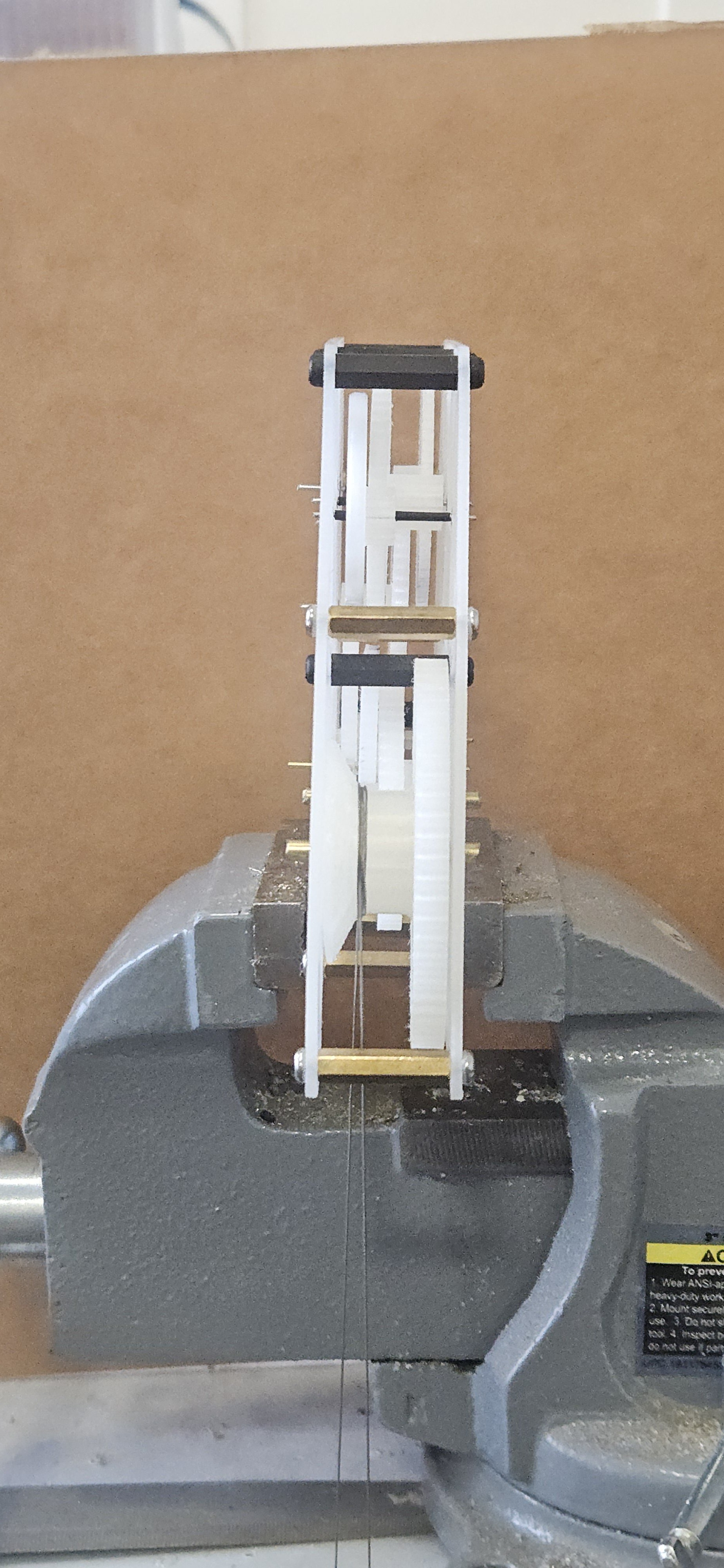
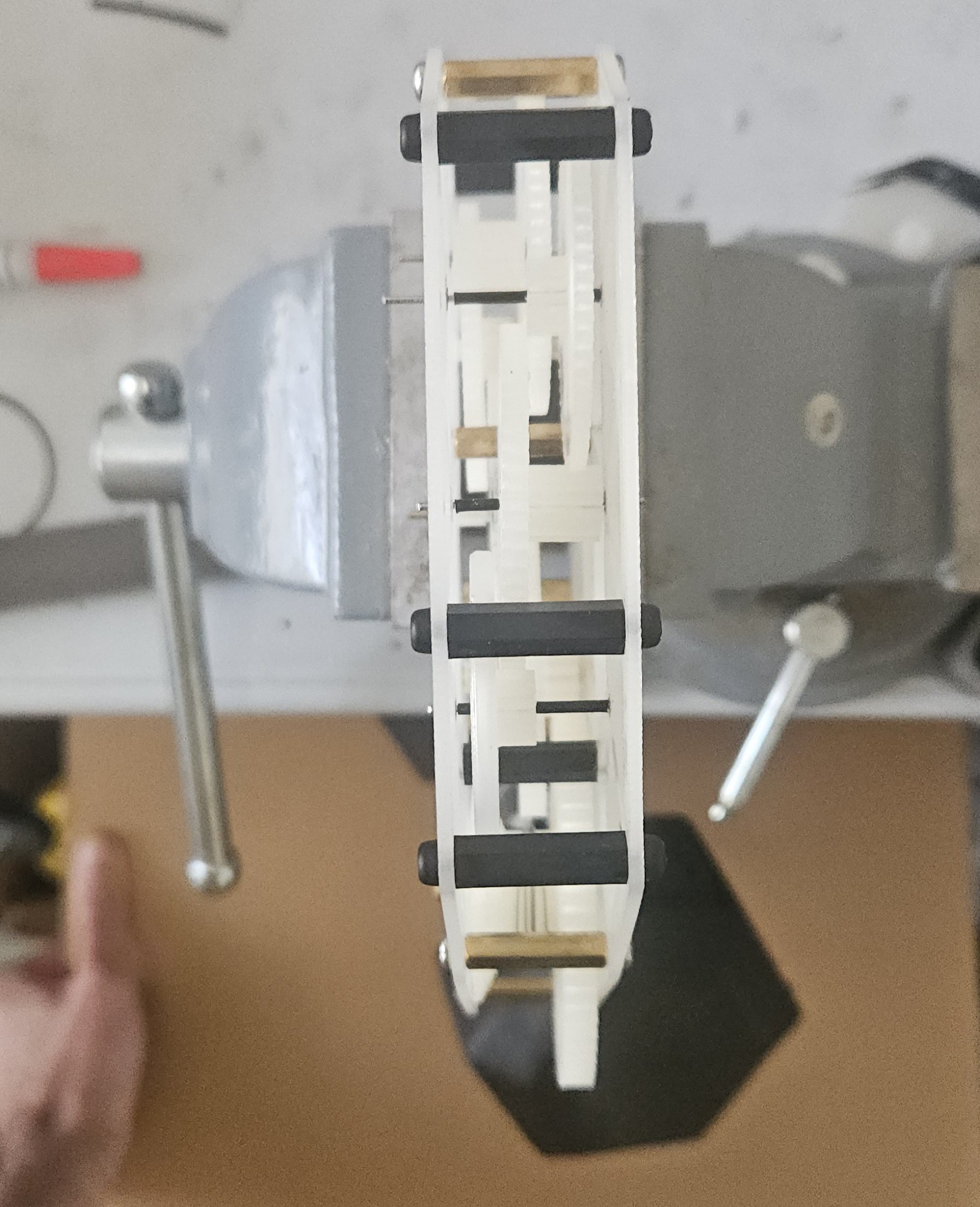
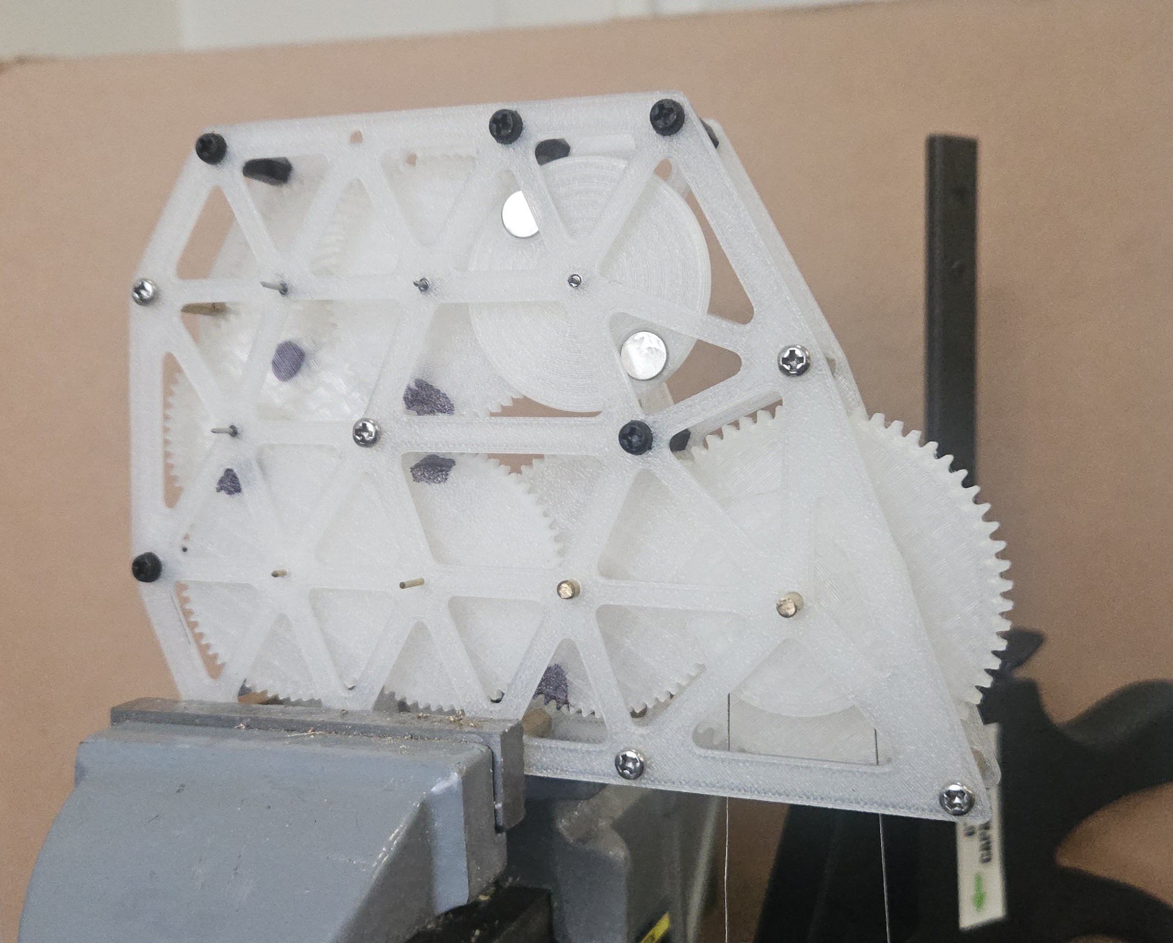
All parts shown in Onshape are 3d-printed with plain PLA. Structure is M3 threaded standoffs. Everything is set up to fit on the bed of my Bambu lab A1 mini.
Stages are a series of double-reduction idler gears:
axle
input
output
ratio
axle
bearing
ratio, tot.
1
spool for rope
60T gear, m=1mm
1
1/8" brass rod
plain
1
2
12T m=1mm
60T, m=0.75mm
5
1/8" brass rod
plain
5
3
12T m=0.75
60T m=0.75
5
3/64" brass
plain
25
4
12T m=0.75
60T m=0.75
5
3/64" brass
plain
125
5
12T m=0.75
60T m=0.75
5
1mm SS
Ball
625
6
12T m=0.75
60T m=0.75
5
1mm SS
Ball
3125
7
12T m=0.75
60T m=0.75
5
1mm SS
Ball
15625
8
12T m=0.75
magnet disc
5
1mm SS
Ball
78125
Input torque is determined by charge mass and spool diameter.
The first few stages of the gear train use plain bearings -- simple brass rods from the art supply store as axles, through a bore hole in 3d-printed PLA. I'm using 1/8" and 3/64" rods for the first 2 and second 2 bearings, respectively. In these first few stages friction isn't really a concern because input torque is high.
The next 4 axles use tiny ball bearings I found on amazon. I bought them to fit into my existing design to retrofit plain bearings without really grokking how tiny these are; by far the smallest ball bearings I've ever seen. 3mm OD, 1mmID, 1mm thick. They reduce friction by a lot; hard to quantify without better testing I don't have time for, but a flicked gear spins about 4x longer than in a plain bearing. Friction becomes exponentially relevant at later stages.
Since the ball bearing ID is smaller than 3/64", I use 1mm stainless steel wire as the axles here. I pull a bit off the wire spool, chuck one end in a drill, and spin it while pulling on the wire with needle-nose pliers. This straightens it, thins the wire a little, and tapers one end for easier assembly.
Gears are spaced on axles using bushings made from 1mm heat-shrink tubing. Clearance is really important.
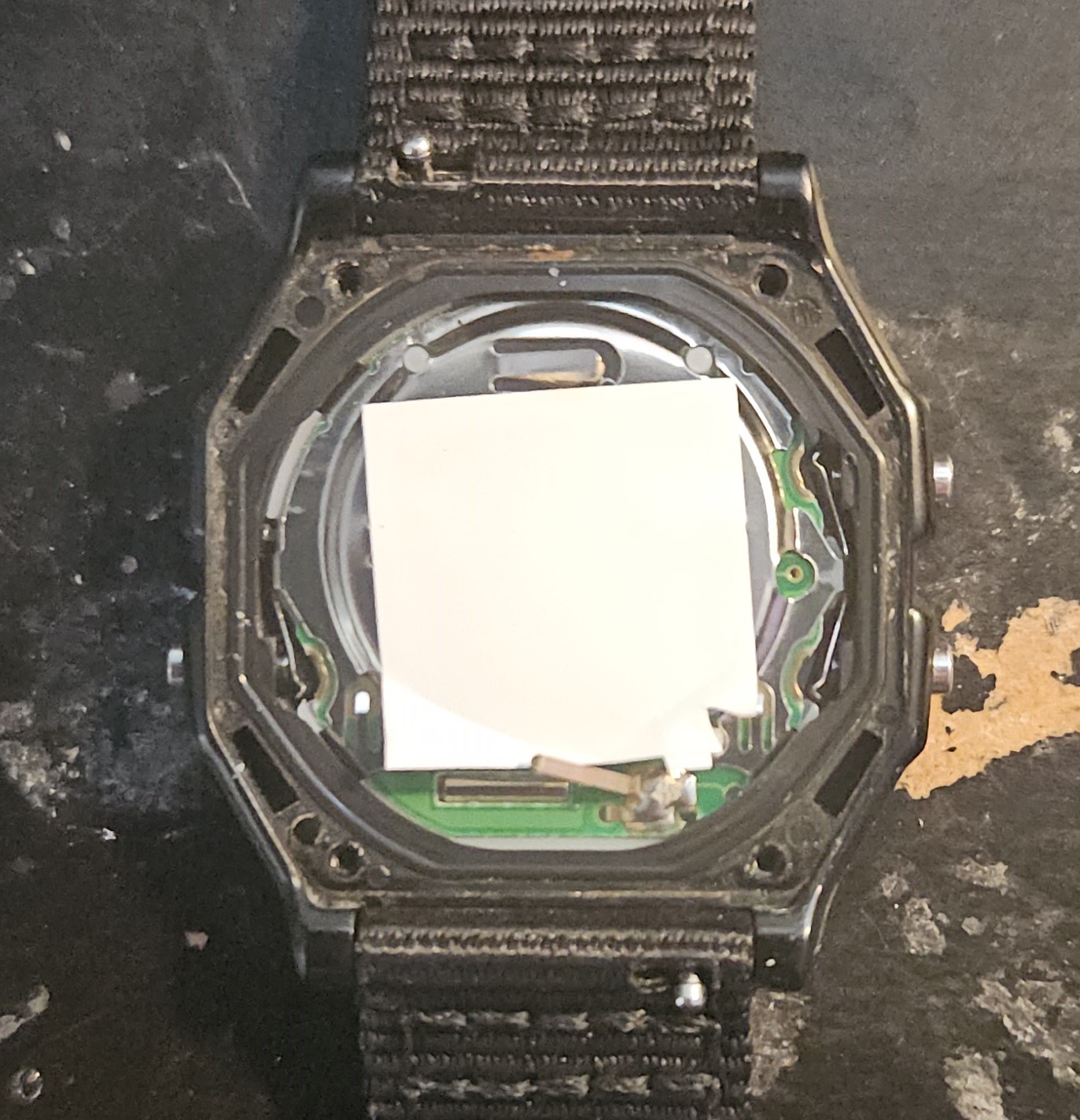
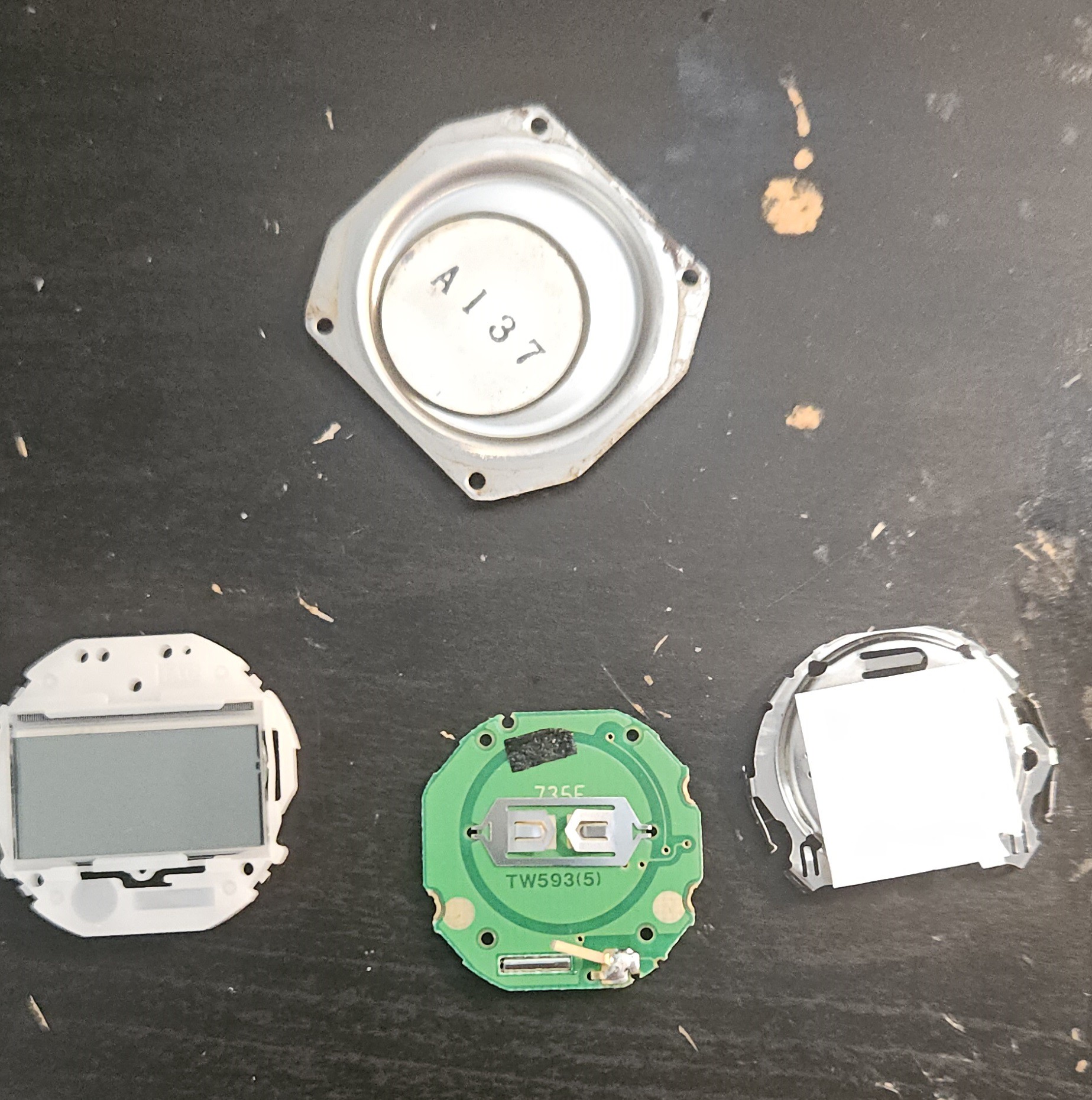
Unclip the battery cover (stamped steel) from the screen chassis (white plastic) by lifting the 4 clips around the perimeter
Remove the battery (might be taped onto PCB)
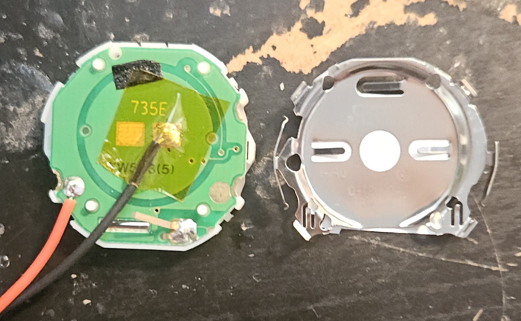
Pull apart the PCB and screen chassis (white plastic)
Remove the negative battery terminal contact spring from the PCB (just pull it off)
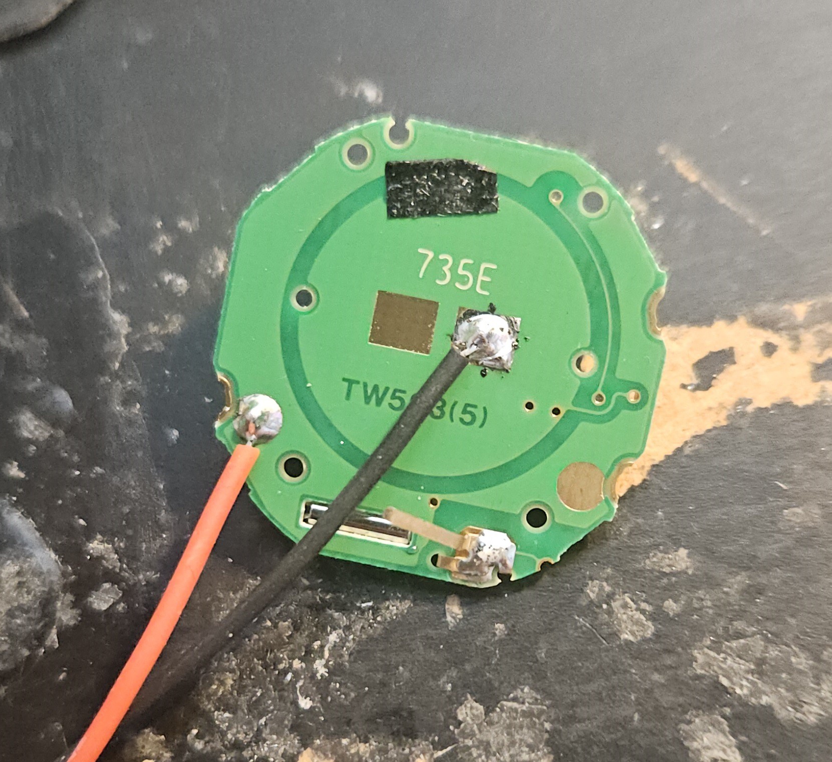
Solder thin flexible wires to the terminals as shown
Cover negative solder joint with tape to prevent short
Reattach screen chassis to PCB (line up the alignment pegs and press gently together)
Clip the battery cover back on, making sure you don't press too hard on the bare LCD
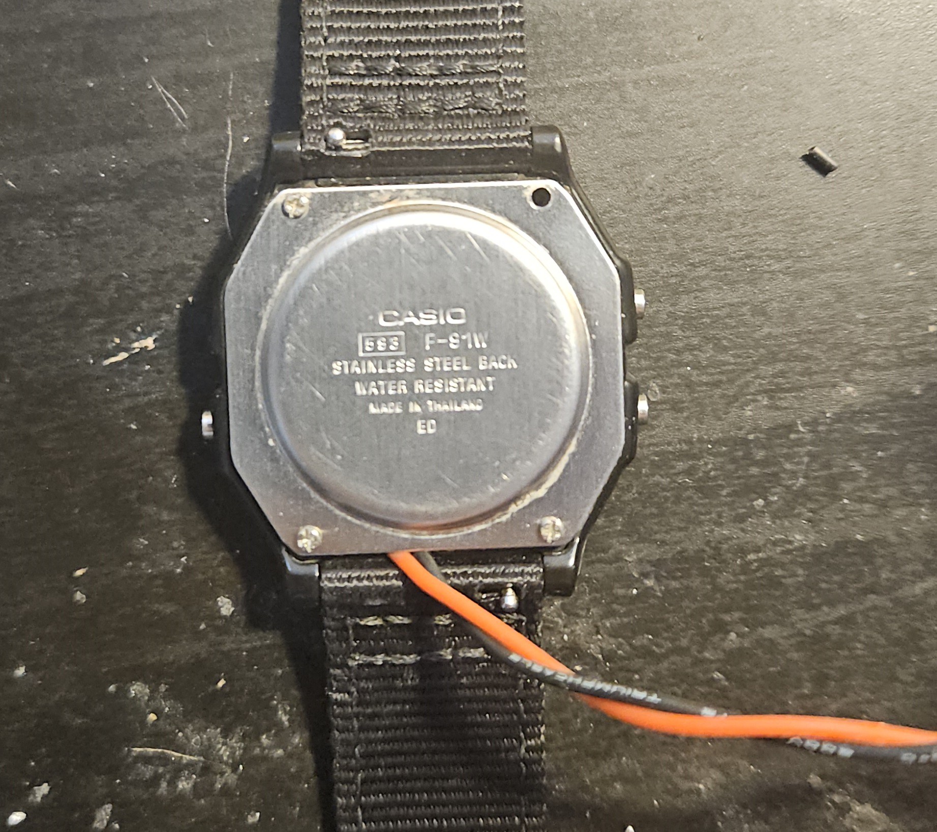
I partially reassembled the watch, partially to protect everything, but mostly to make sure I don't lose any more parts. The back cover screws are very long, so if you just partially tighten them the wires stay comfortable.