YARRM - 7-DOF Low-Cost Robot Arm
Yet Another Robot aRM - where I develop a low-cost compliant robot arm with a 1meter reach, 1KG payload.
Yet Another Robot aRM - where I develop a low-cost compliant robot arm with a 1meter reach, 1KG payload.
To make the experience fit your profile, pick a username and tell us what interests you.
We found and based on your interests.
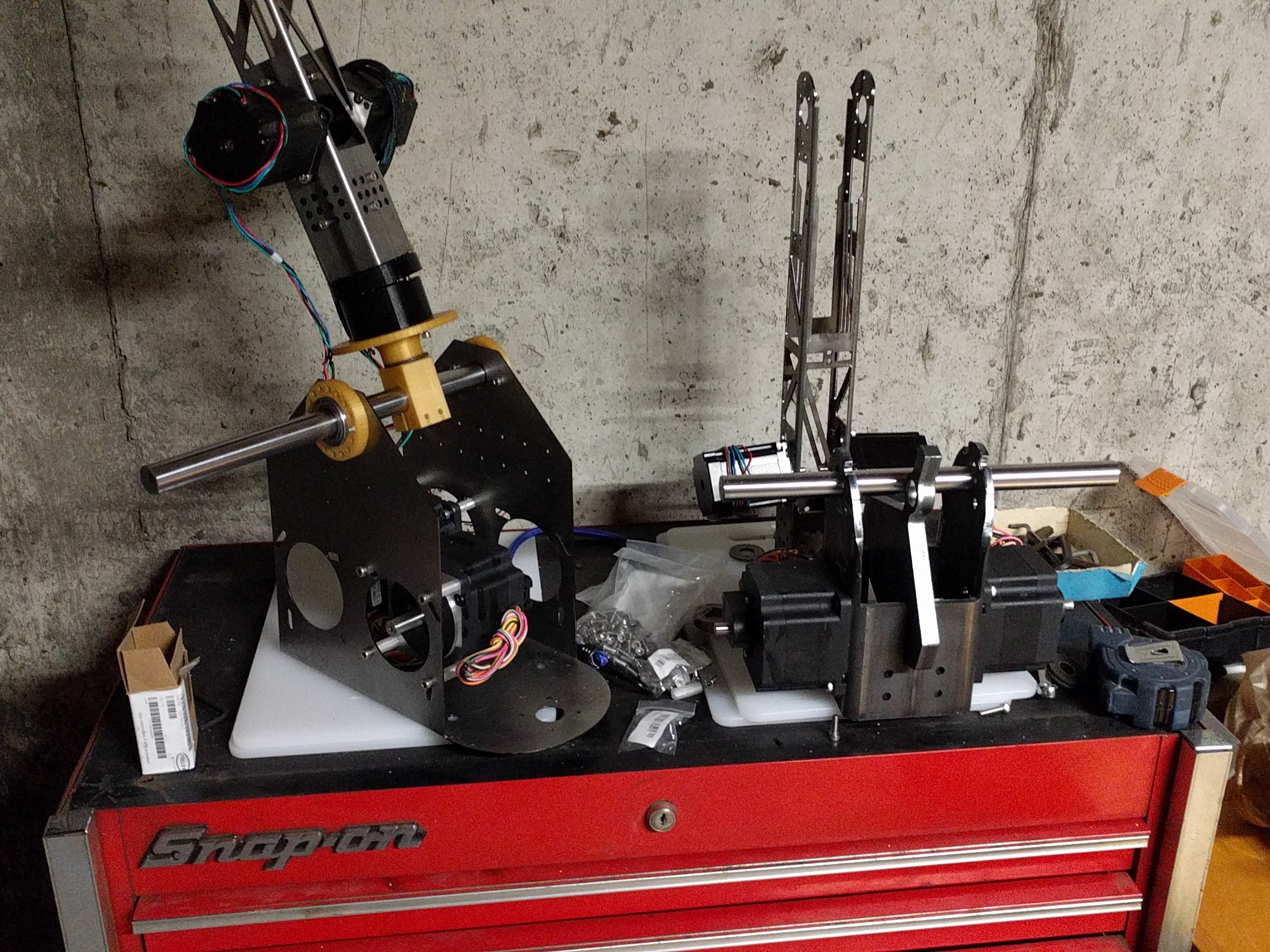
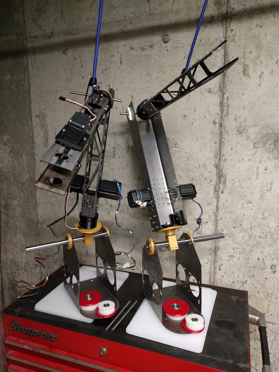
Started assembling the new redesigned robot arm!
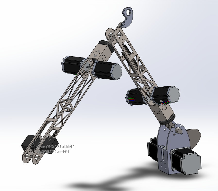
After having built the first two iterations, I realized I needed a better base design. I wasn't happy with the accuracy or stiffness of the 16ga steel folded at 90degrees so I have decided to move the motors eternal to the arm structure, which ends up making it quite a bit more compact. It is also a bit similar to the design now in use by Boston Dynamics "mini cheetah" / electric mini-dog arm.
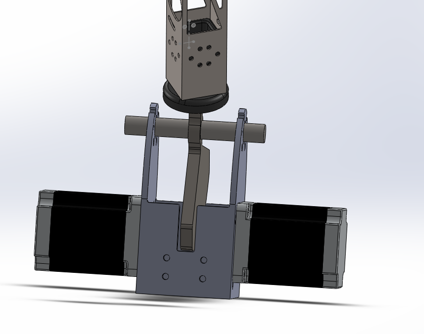 Here the motors are still NEMA34s geared ~4:1 or 5:1 to the 20mm axle.
In order to counteract the base torque, I have added a counter-weight (with associated cutouts) which also acts as the thrust washer mount/pivot. The counter-weight is massive - 1/2" steel plate laser-cut, weighing around 3 lbs!
I have kept the original adjustable base tensioner:
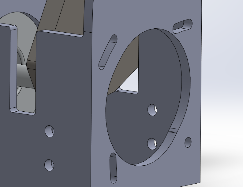
and now also added them in the arms:
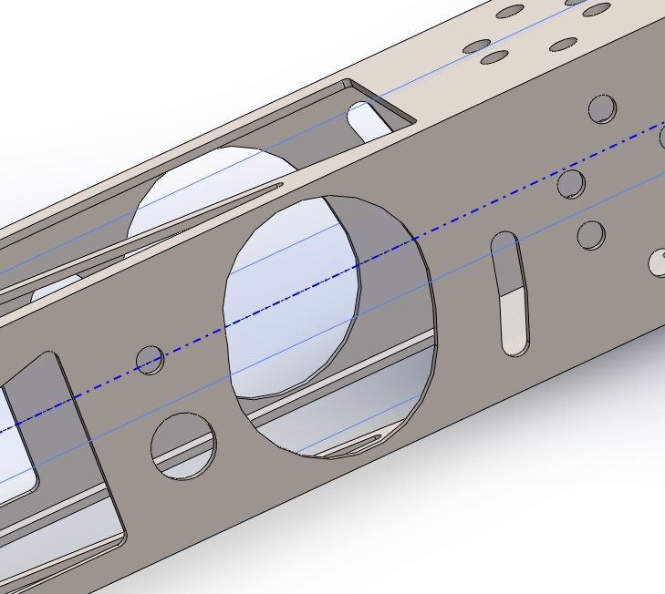
Here you also see one of the modifications I did for assembly - the motors are installed on the diagonal (small hole + slot). The larger hole is for being able to assemble the opposite side motor.
Thoughts on the redesign?
I have ordered the parts and hope to start assembling this weekend (iteration 3). It's a long process and I hope to get the motors moving soon.
In the meantime, I will try to get the existing arm moving a bit. I have bought three Makerbase MKS V1.3 32-bit smoothie clone boards as testbeds (so I don't fry my legit Smoothieboard 5XC), I hope to connect them up and start testing soon.
Thanks for listening.
Laser cutting definately have advantages. One is that steel makes an excellent spring material.
Why not kill two birds with one stone?
I've now integrated adjustable leaf springs into my laser cut tube directly.
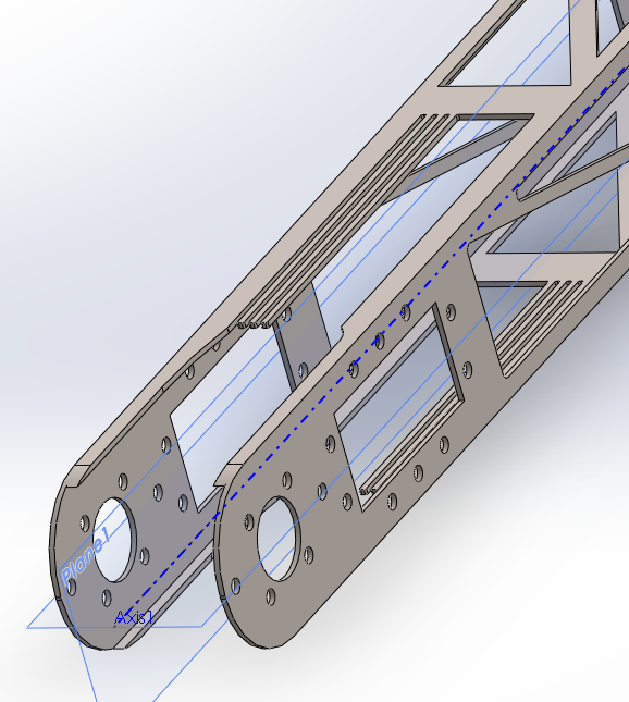
The springs are the three "lines' present, which are not directly mirrored but are set 180degrees from each other on each side. By changing the thickness of the printed "counter-balance", I can "engage" one, two or three of the springs. In addition, I can change the preload by redesining the printed part, or by adding a u-bolt around the entire tube (similar to truck suspension).
This is one of the possible designs I have been considering for the stackable "pusher". As you can see it is bolted to the 8mm axle pivot (which is now a solid aluminium bar instead of a printed part with bearings).
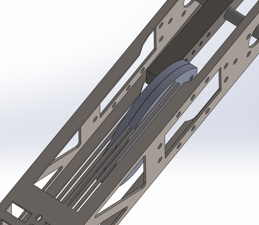
In the first picture you also see some modifications to the old tube design (which was squared off and which was snagging on the rotator/pivot). The end is now all curved to allow the pivot to go around. In addition I added holes for IGUS igubal self-aligning bearing installation.
On the base I have added a very large (huge) counter-weight to balance the arm. See next post for more details on that and the rest of the substantial redesign, all of which originated from building the original arm.
After assembling the first, then the second arm, I am really getting tired of tapping all those threads manually in the plastic. I am thinking of just using heat-inset tapped inserts but it would be another thing to buy for everybody. Also bolting the motors and joints take too much time (especially with nylock nuts). Any suggestions for making things easier?
Here are pictures of the two together.
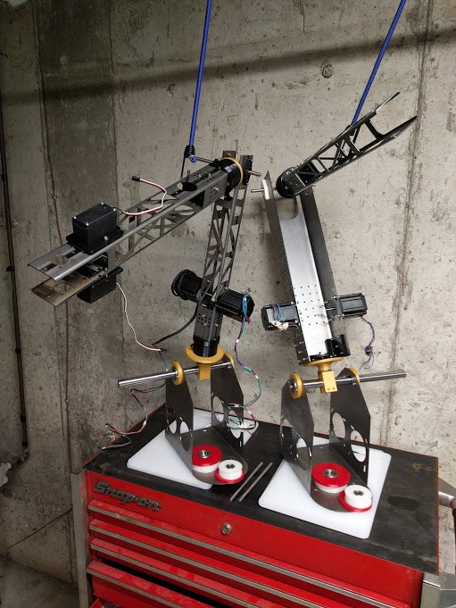
Already so many parts need some redesigns, I'll be updating the STLs on Github hopefully before the weekend.
What feature do you want to see in the robots? Any suggestions for the next post?
The original goal of the robot arm was to have a high-accuracy 4-DOF palletizing robot.
However over the last few months I have been working on something far more adaptable - a 1meter reach collaborative robot arm with 7 DOF. The arm should be just as accurate when combined with visual servoing with a camera on a stick above the robot and one on the wrist.
The main design architecture of the arm is a NEMA17 stepper on the base to rotate it, and differential drives on each pair of joint DOFs after that - NEMA34 on the base, NEMA23 on the first arm and extra-large size servos (~30 kmcm) on the last arm.
The end-effector connector is an ISO-standard mount (same as on the Universal Robot UR3/UR5/UR10 robots).
On the github project link you can find the files in STL (3d printed parts) and SLDPRT for the metal parts (Solidworks design but I'll try redesigning them in Solvespace). The issue tracker there is also live.
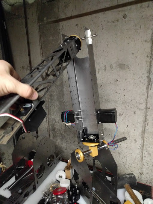
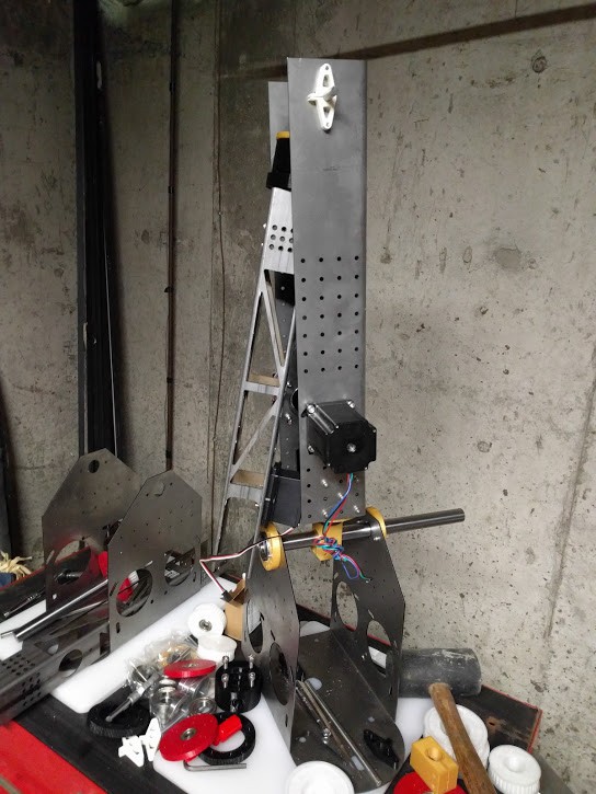
See pictures below for the first arm build (which has already been modified to save weight)
In order to get a better idea of the mechanisms involved, I ordered and assembled a MeArm. I must say, for the price it's unbelievable! Here are a couple of photos.
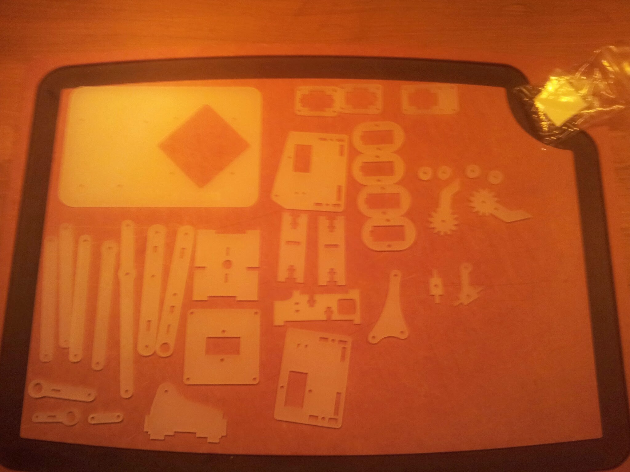
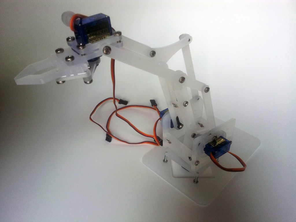
There are a few improvements I'd make. One, I wouldn't try supporting the entire mass of the arm a tiny 9g servo. I would try to support it on a bearing plate, or thrust washer or something similar. It can even be a piece of plastic. Two, actually there is no two! It works well!
In order to start designing mine, I have begun to use the above 2D-lasercut parts as a "baseline" for my own arm. I used to use Solidworks but now I'm trying to keep it all open-source including the design. Thus, OpenSCAD. I have posted the beginning of my SCAD code here:
https://github.com/jonnycowboy/armGen/blob/master/arm.scad
which will let you parametrically design any of the support arms above, in 2D. You can then export a DXF for cutting directly.
Need some input on what kind of controller I should use.
It will either be an arduino (because most people already have one) or the Raspberry Pi.
Servo driver will use the chip from the Adafruit 16-channel servo driver (i2c control).
I'm leaning towards the RPi just so that we can run some basic OpenCV code on it to set part localization (PickNPlace) usage).
Thoughts?
Here are the links for inspiration for my project
Reverse-engineered uArm by ArmaTec : http://www.thingiverse.com/thing:320004
Marginally Clever's 3DOF Palletizing Robot: http://www.thingiverse.com/thing:280263
uArm: http://blog.ufactory.cc/category/robot-arms/
ABB 460: http://new.abb.com/products/robotics/industrial-robots/irb-460
Phenoptix me-arm: http://www.instructables.com/id/MeArm-Build-a-Small-Hackable-Robot-Arm/
Me-arm inverse kinematics! https://github.com/phenoptix/me-arm-ik
Phenoptix meArm Max (just shown yesterday!) http://www.thingiverse.com/thing:404062
Smokie Robotics arm http://www.smokierobotics.com/
Create an account to leave a comment. Already have an account? Log In.
Interesting, I assume a mostly metal setup, am I right?
Pity about dropping the encoder since it is good to know where every is after a power fail-
assuming that the encoder is an absolute encoder.
My preference would be to have absolute encoders on each joint, but thats just me.
Are you going to offer this for sale and ,if so,ship to the EU?
Thanks for your comment. I agree encoders would be nice but it would entail more custom parts, electronics and especially cost! If I ever change from steppers to DC servos I'll have to add them back, but for now with all the 3D printers out there, stepper control boards are just so cheap so as to not be worth it to us anything else (at that price point).
Regarding putting it up for sale - that would be ideal yes but not 100%sure yet. Depends on how well it works. I would sell in the EU as well but shipping would be pretty expensive, 100-200$ given the package dimensions and weight (about 1m x 0.25m x 0.25m and 10kg). Best option would be for me to partner with somebody locally in the EU.
there are plenty of EU-based vendors you could join-venture with. first biz that comes to my mind is http://exp-tech.de/ - you'd drop them an email. regards
I really like the look of the laser cut steel tubing. Might have to consider that when it comes time to make a new frame for my project.
Let me know if you have any questions about cutting flat stock and tubing -cost, materials, etc
Do you really need to know where your end effector is to within ~26 μm?
Thanks for your comment. I've changed approach now - there will be no encoder and instead I will use steppers. A camera will be used for visual servoing.
Thinking about this again, I think having extra angular resolution at the pivot might actually be helpful in using PID to compensate for imperfect material/structural stiffness.
Become a member to follow this project and never miss any updates
By using our website and services, you expressly agree to the placement of our performance, functionality, and advertising cookies. Learn More
 Petar Crnjak
 Aaed Musa
 Dimitris Xydas
 Val
Val
It looks like designing and building one of the differentials may be a good next step. These are what will make or break this project. Are you really trying to drive this precision arm with friction differentials as some pictures suggest? Or are those going to replaced with bevelled gears? Good gears will also have a big impact on the overall costs. Or are they cable driven?