Close
0%
0%

Programmable inverter

Make a cheap consumer inverter generate variable voltage & more easily start motors.

Similar projects worth following
340 views
0 followers

It began with Dave getting a $2800 programmable inverter  & lions thinking there must be a cheaper way.

There aren't any more hackers hacking inverters because everything is sponsored nowadays.

  • Enclosure

    lion mclionhead3 days ago 0 comments

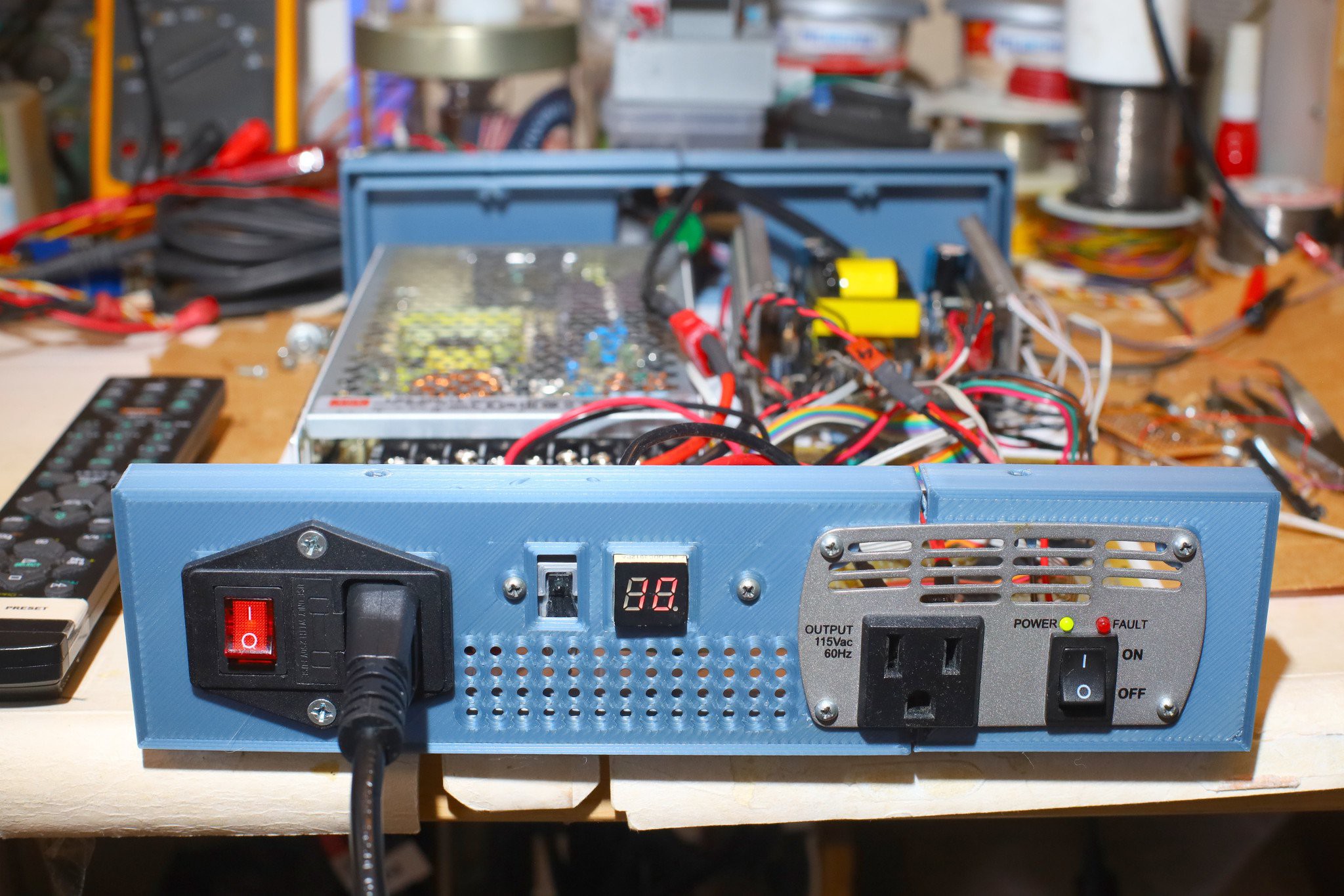
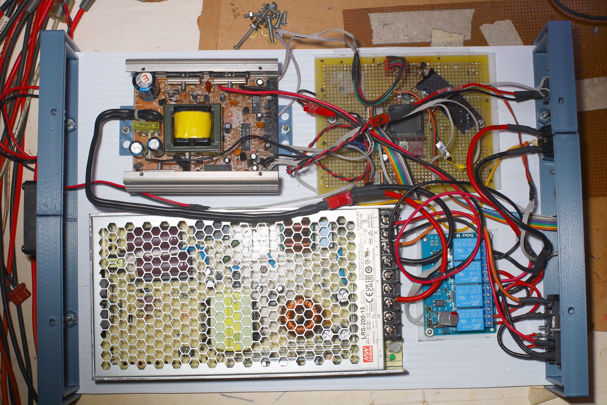
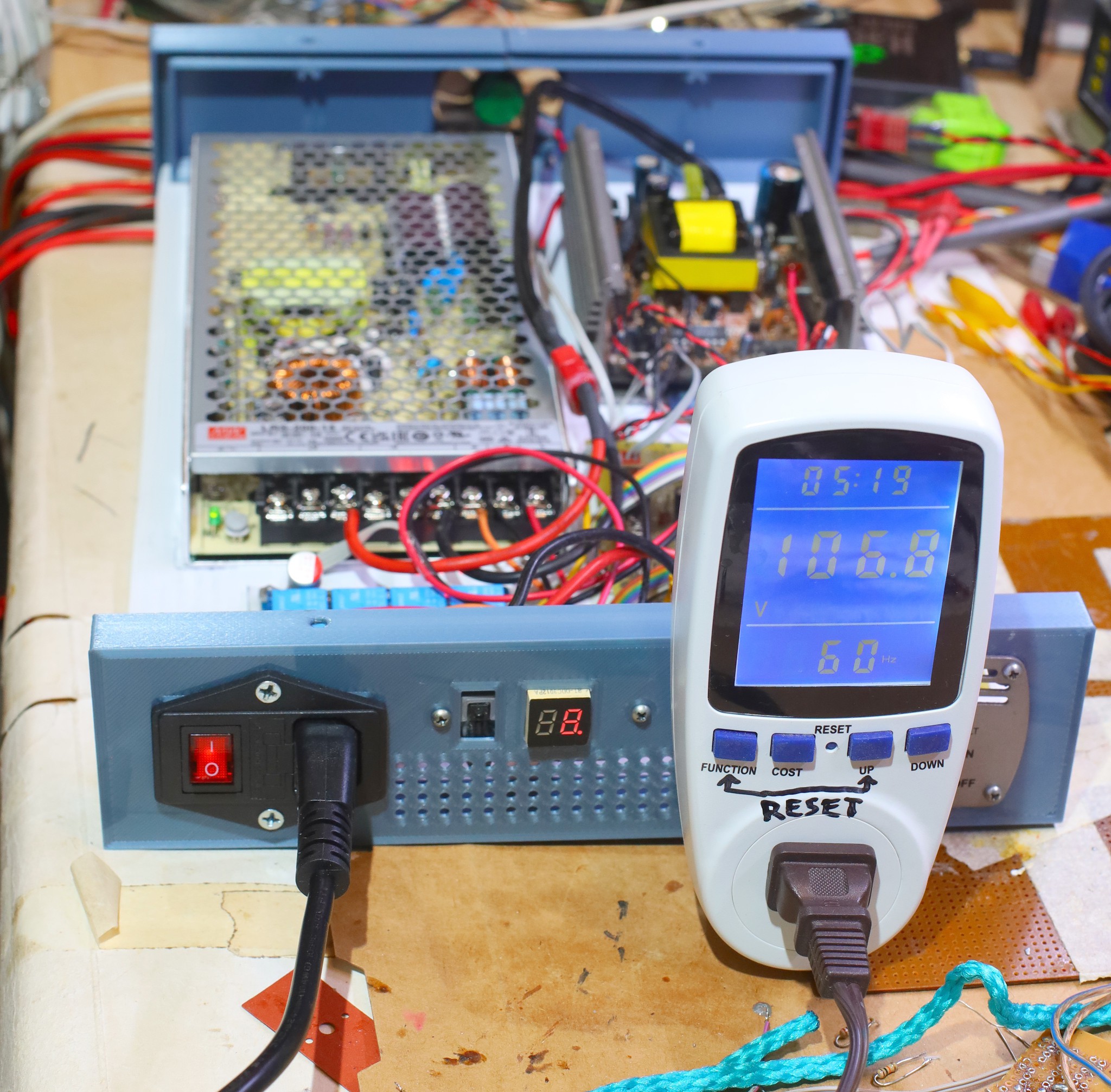
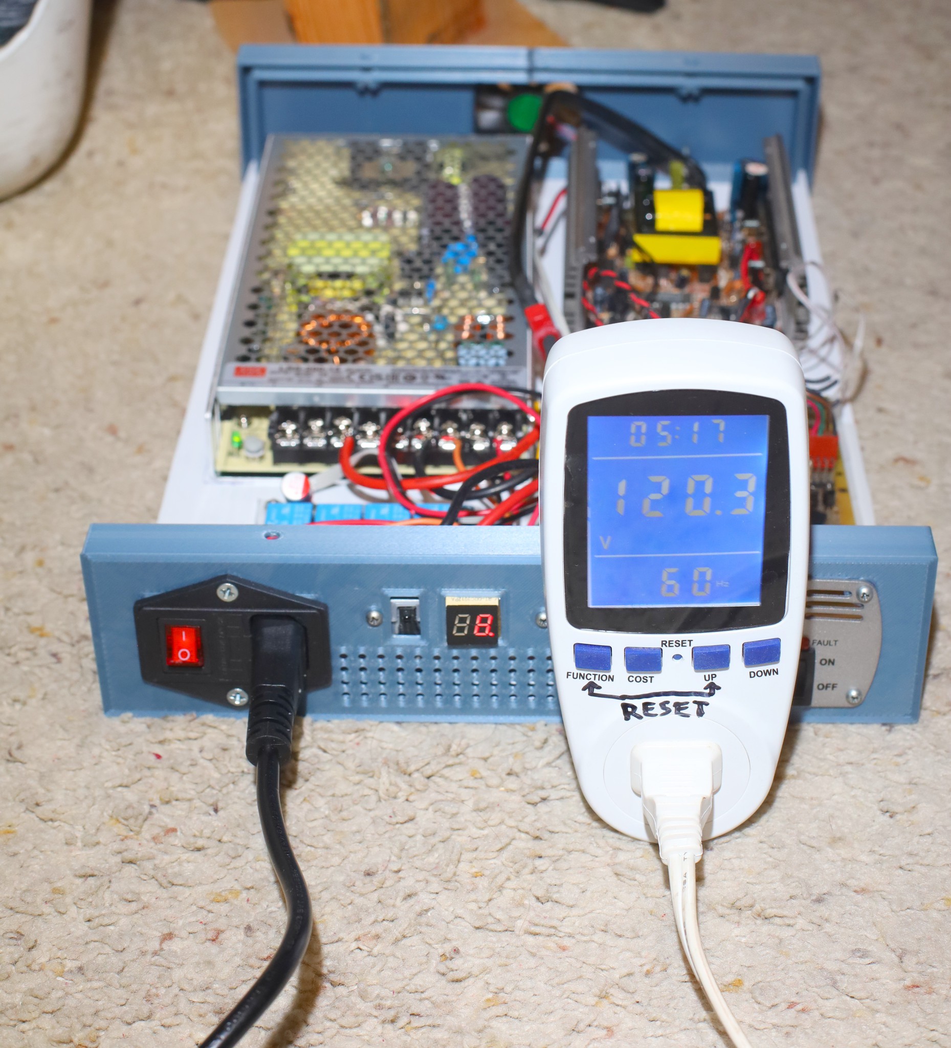
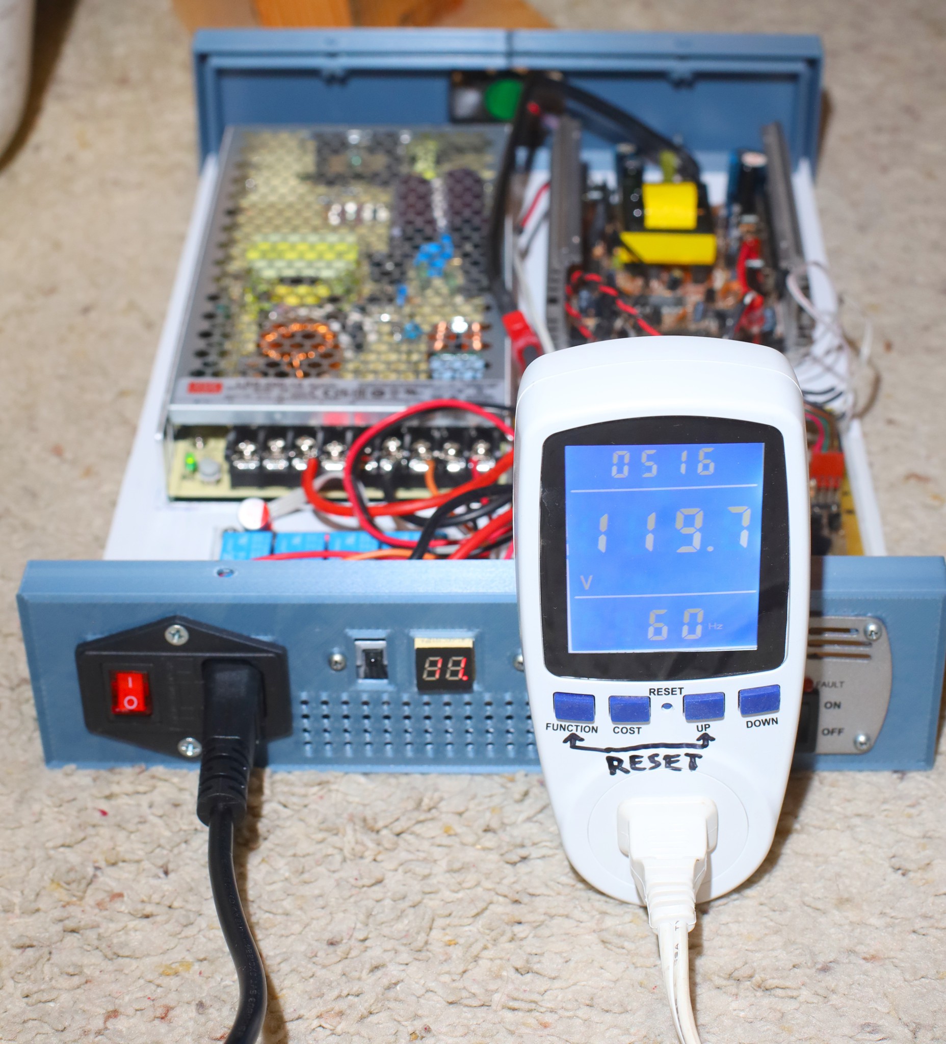
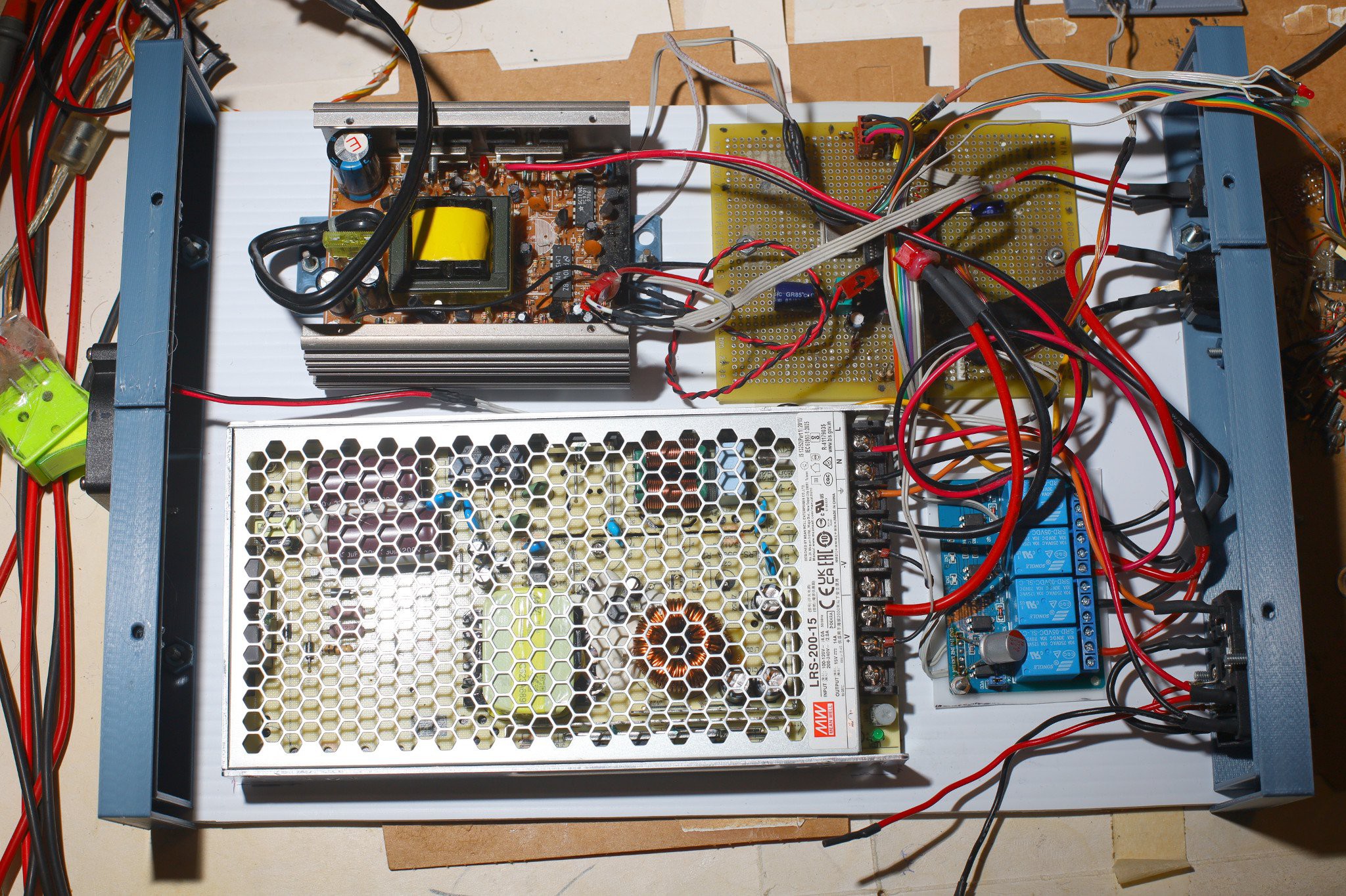
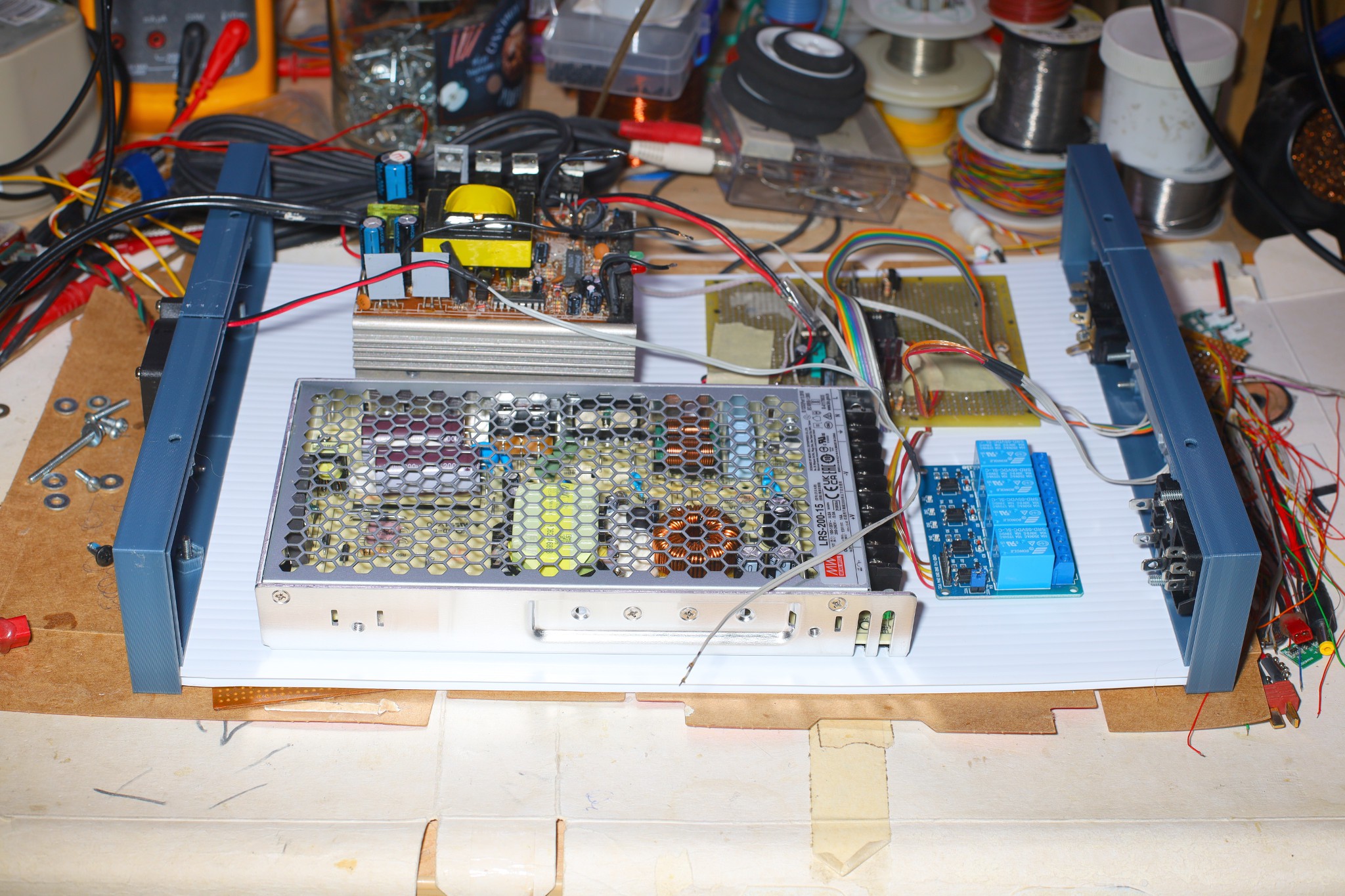
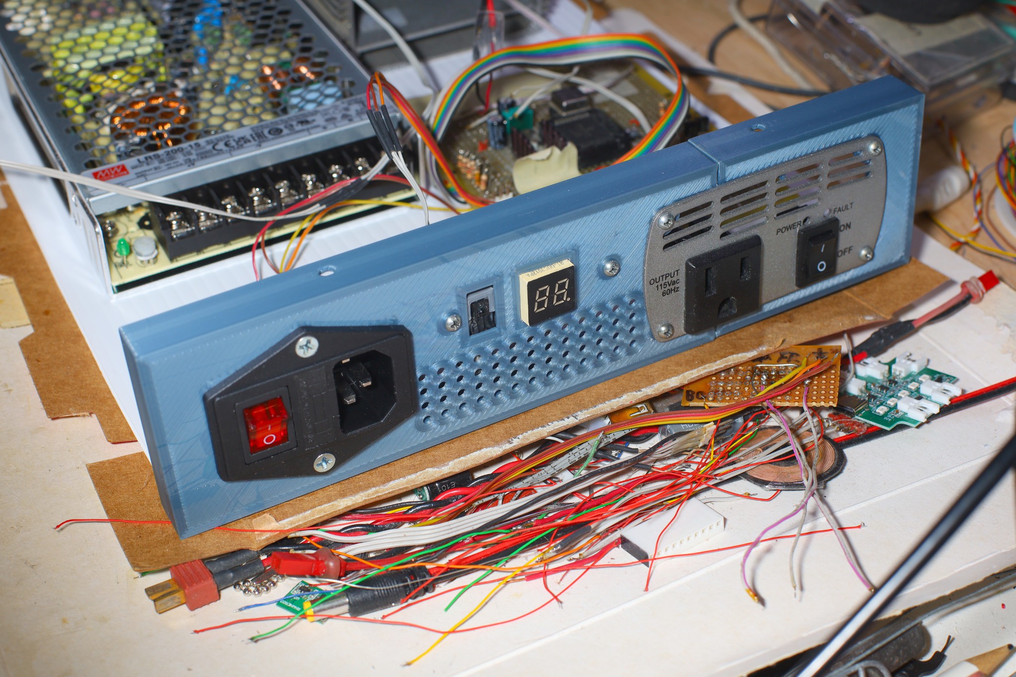
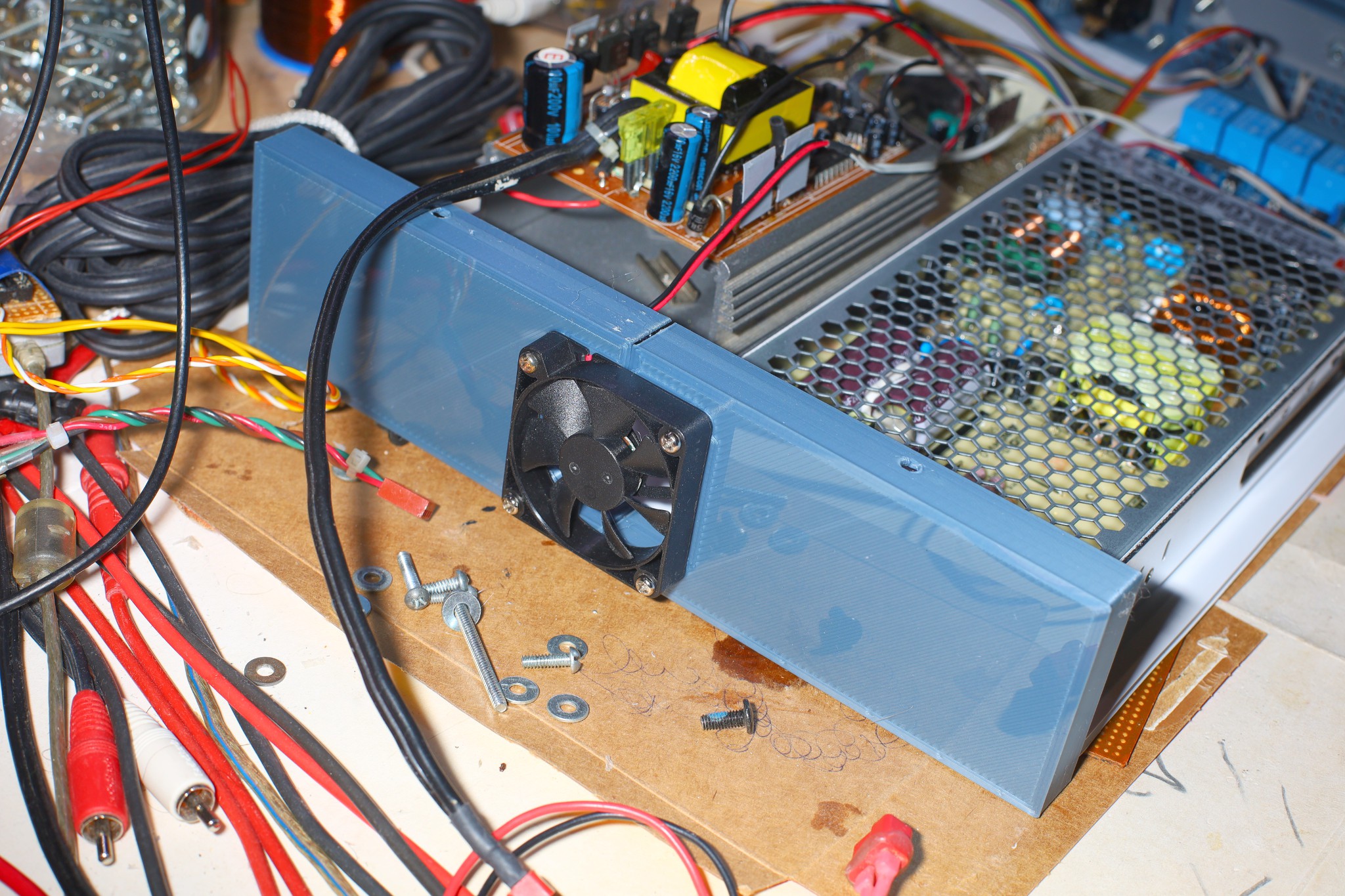
    A few pounds of PLA later, the enclosure wasn't feeling very warm & fuzzy.  Like the days when lions built H bridges from scratch, there's probably an off the shelf enclosure for a reasonable price.  It seemed to need a 2nd layer of coroplast.  It wasn't clear how reworkable it would be.  Connections would have to use screw terminals wherever provided.  A battery connector would connect the inverter + control board to the Meanwell.  Then it could be powered from the bench for testing.

    The inverter + control board + relays would have to be 1 unit because of the large number of connections.  The fan would need a connector, possibly going straight into the meanwell.  Some empty space was provided for the fan to blow into.  The fan would run continuously, since the relays get hot. 

    Started pivoting back to 10 voltage steps with 10 being bypass, since battery power is never going to be used.  Nowadays, it's more common to have 12V DC fans for off grid use.

  • Relays

    lion mclionhead6 days ago 0 comments

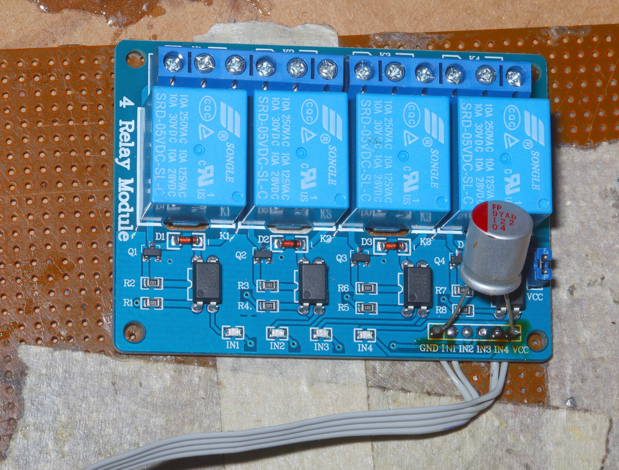
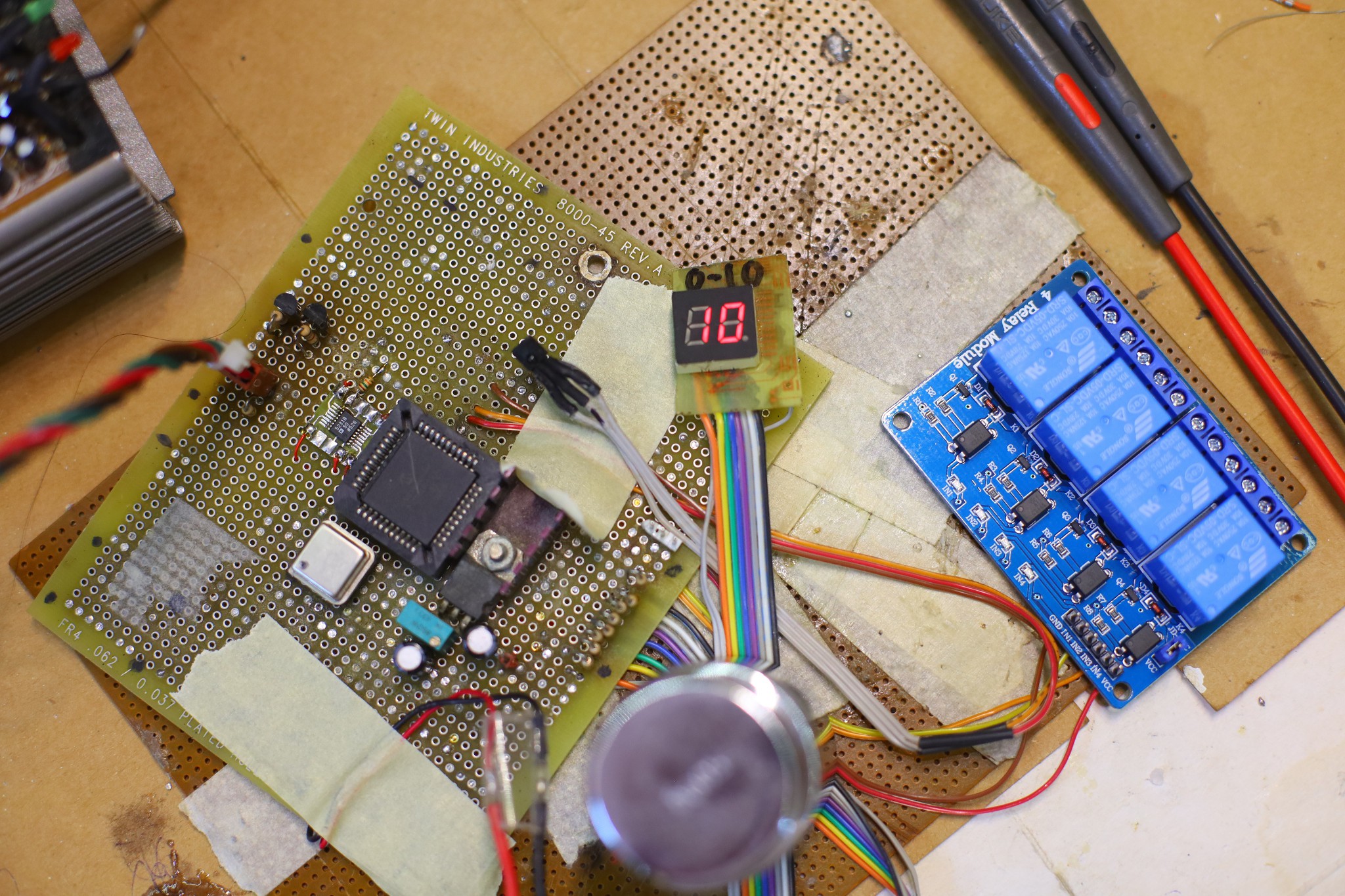
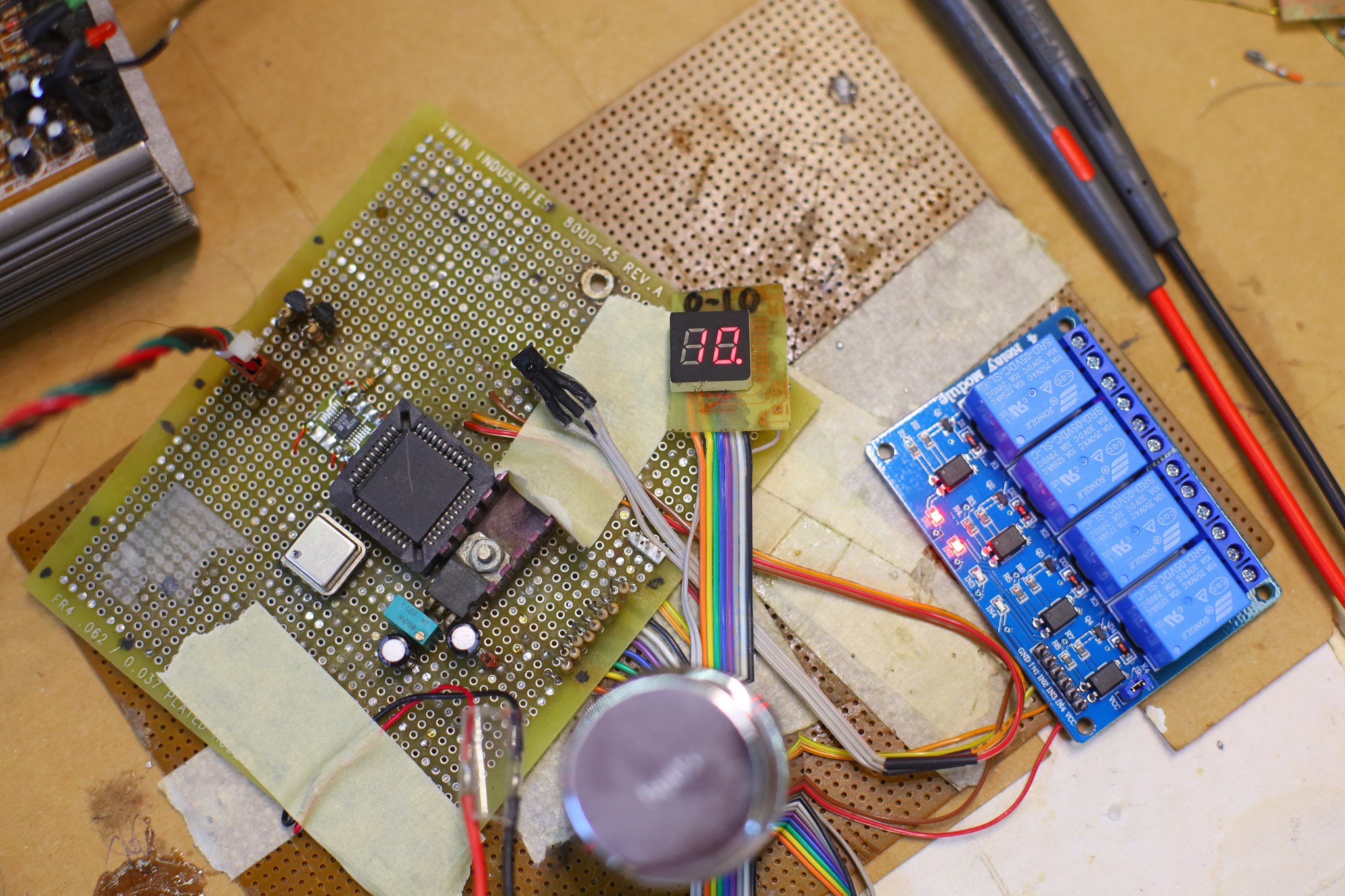
    A complicated algorithm for the relays evolved to where they're directly toggled on & off by the power button.  They connect the inverter for voltages below 11.  They connect manes for 11.  10 sets the maximum inverter voltage, which could be higher than manes, but could also be battery powered.  They wait a while in the off state when switching between relay & manes.  They always switch off with no delay.  The delay avoids back EMF & the chance of a timing glitch briefly connecting manes to the inverter output.

    Of course, the very thought of that timing glitch & the chance of a relay getting stuck has lions pondering not allowing a manes bypass at all.  The piece of mind might be worth the lost efficiency.  It needs to sense the outlet is off before powering the inverter.

    The relays suck a hideous amount of current, 75mA for each one that's on.

    Putting it all together requires mounting everything on the enclosure base plate.

  • Though hole rebuild

    lion mclionhead06/29/2026 at 08:45 0 comments

    It became clear that it needs to switch to manes voltage for the maximum power setting with some kind of relay.  It's not a piece of test equipment but going to be powering a blower all day, normally at maximum.  Not just the live but the neutral has to be switched, because inverter neutral is live.  To avoid putting negative voltage & back EMF on the MOSFETs, it needed an open circuit state for a time between selecting the inverter & manes so that meant 4 relays.

    Another idea was to have a way to plug in a battery between the Meanwell & the inverter.  That would allow it to still run as a conventional inverter or power the blower without manes, for a short time.  This would need a manual switch.

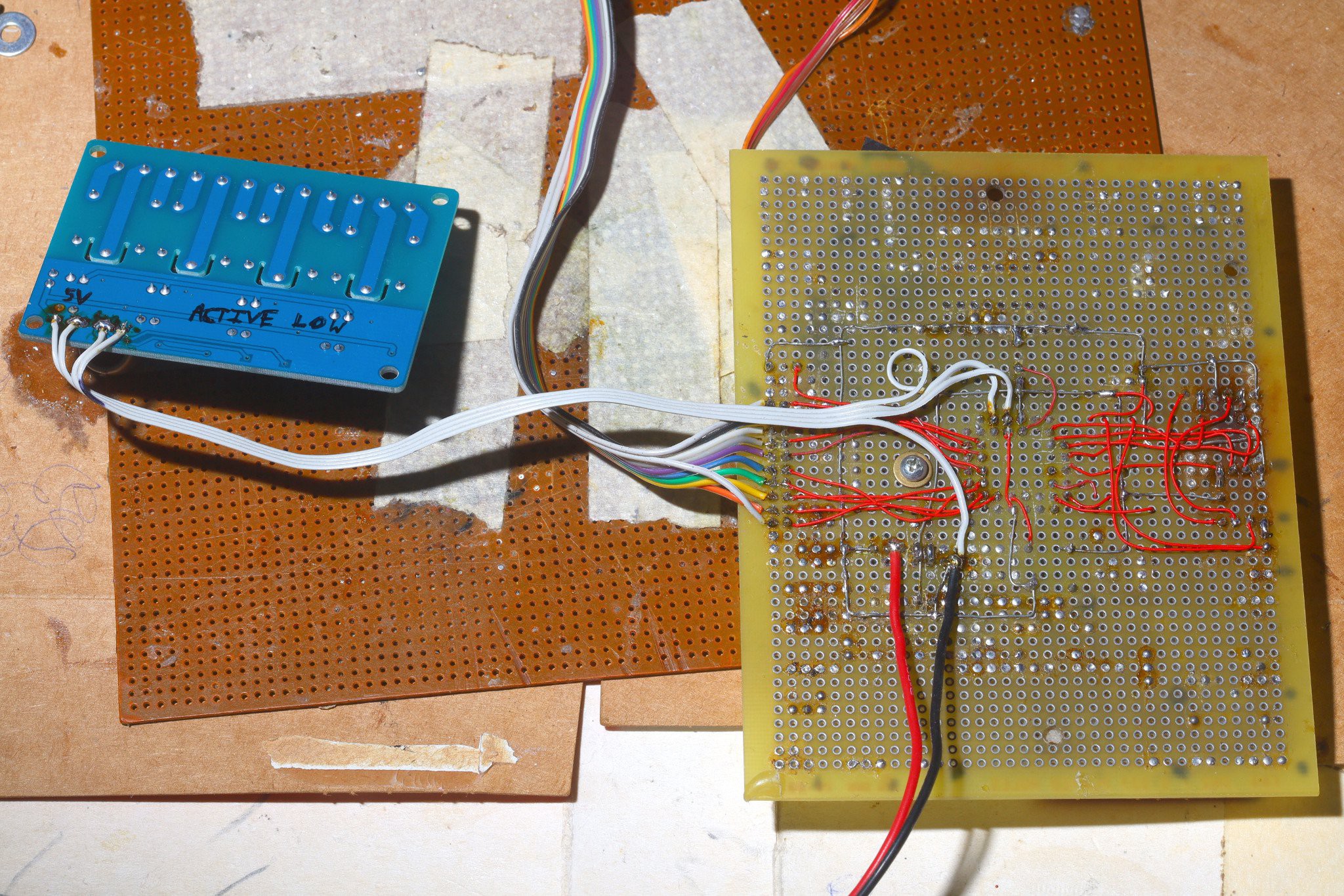
    Also, given the new need for relays, decided to rebuild the hacker board with vintage components, for vintage appeal & to get rid of some parts.  It was slow going, in the old days. 

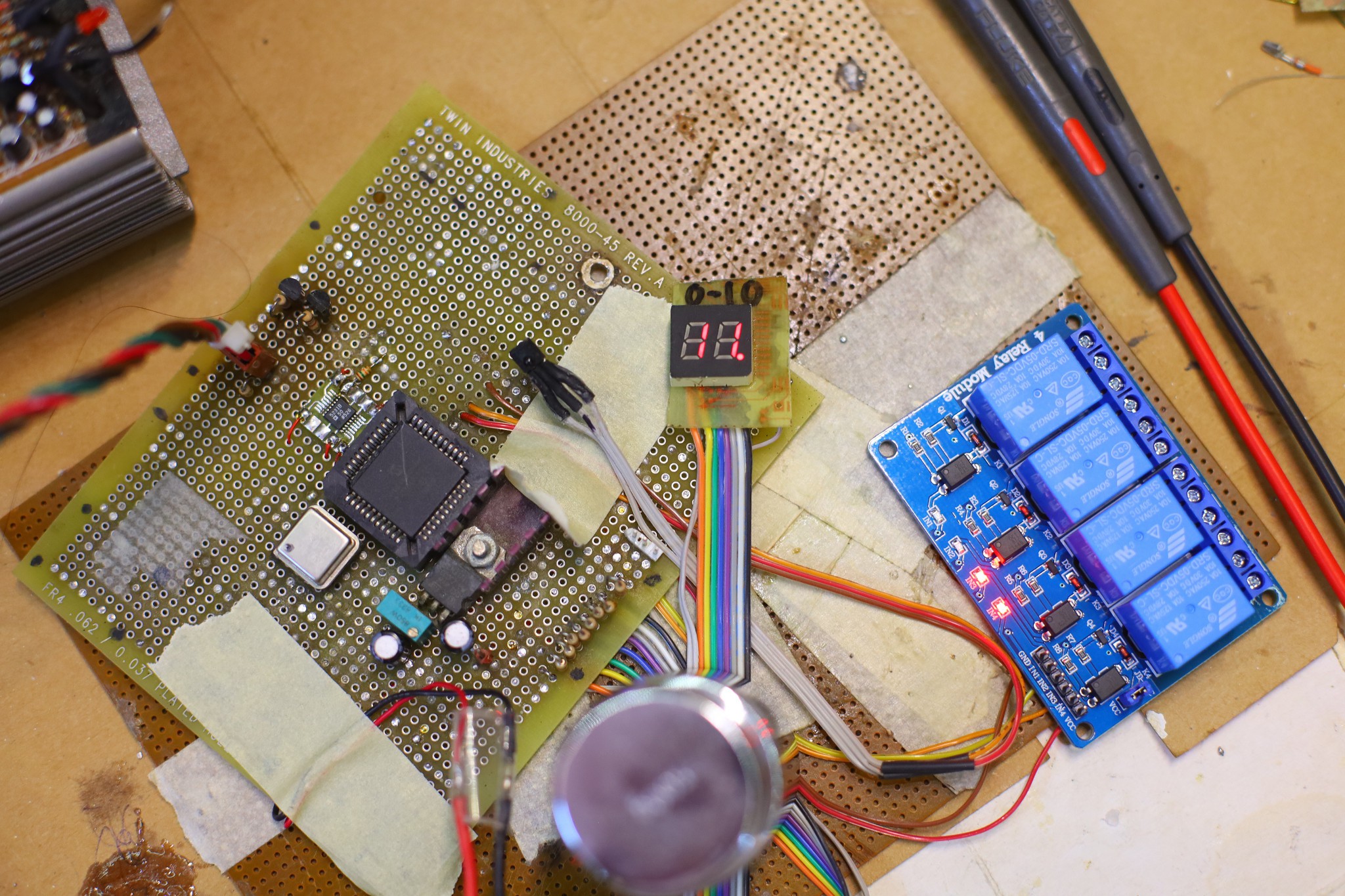
    This board dated back to Aug 2008, went through many crashes, hopefully won't be reworked again.  The LED panel dated back to 1997. 


    It would go in a big ass coroplastic/PLA rack enclosure.  It would need a thermostat controlled fan.

    At this point, it started becoming clear how overdone this was, compared to a simple dimmer switch.  A remote controlled dimmer switch could have used a servo & cost nothing.  It would probably have been just as noisy as the inverter. 

     There's a chance increasing the frequency could reduce the noise.  Commercial inverters make real sine waves with PWM.  Then they have a very large LC filter to smooth the manes voltage side.  It's a tradeoff between efficiency & noise.  Lions don't have the budget to create a fully functional frequency & voltage interface.  A voltage indicator from 0-10 is as good as it gets.

    ----------------------------------------

    Tearing down a newer Rhino 400W inverter, it would be a more destructive process to remove the brownout protection & synthesize a custom waveform, but it could be done with a lot of effort.  The transformer driver would have to be completely replaced.

    Reviewing modern options, square wave inverters below 1kw are now few & far between.  Cheaper off grid solutions have driven the market to true sine wave, grid replacements.  No-one tears them down anymore, but presumably they all have a big LC filter.

    -----------------------------------------------------------------------------------------------

    EG8010 notes:

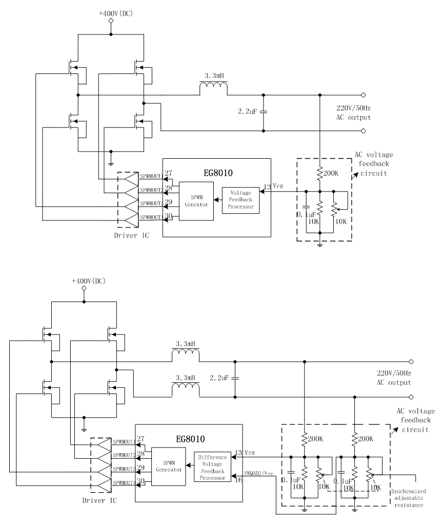
    Everyone was building sub kW sine wave inverters from the same EG8010 widget board, years ago.  All those projects have bit rotted, because of the liability.

    https://www.amazon.com/dp/B07T7VY756

    That creates the sine wave with PWM but doesn't perform the voltage boost.  It has full frequency & voltage control by adjusting a feedback resistor.

    The datasheet shows an example LC circuit for a unipolar & bipolar configuration.  In unipolar mode, 1/2 of the bridge gets PWM while the other half gets DC.  In bipolar mode, the full bridge gets PWM.  Bipolar mode resulted in better filtering.  Fully adjustable frequency was only possible in unipolar mode.  It had a serial protocol for setting the desired feedback voltage & the frequency range in unipolar mode.  The PWM ran at 24khz, just above lion hearing.   A blower could be noisy enough to negate the square wave humming.

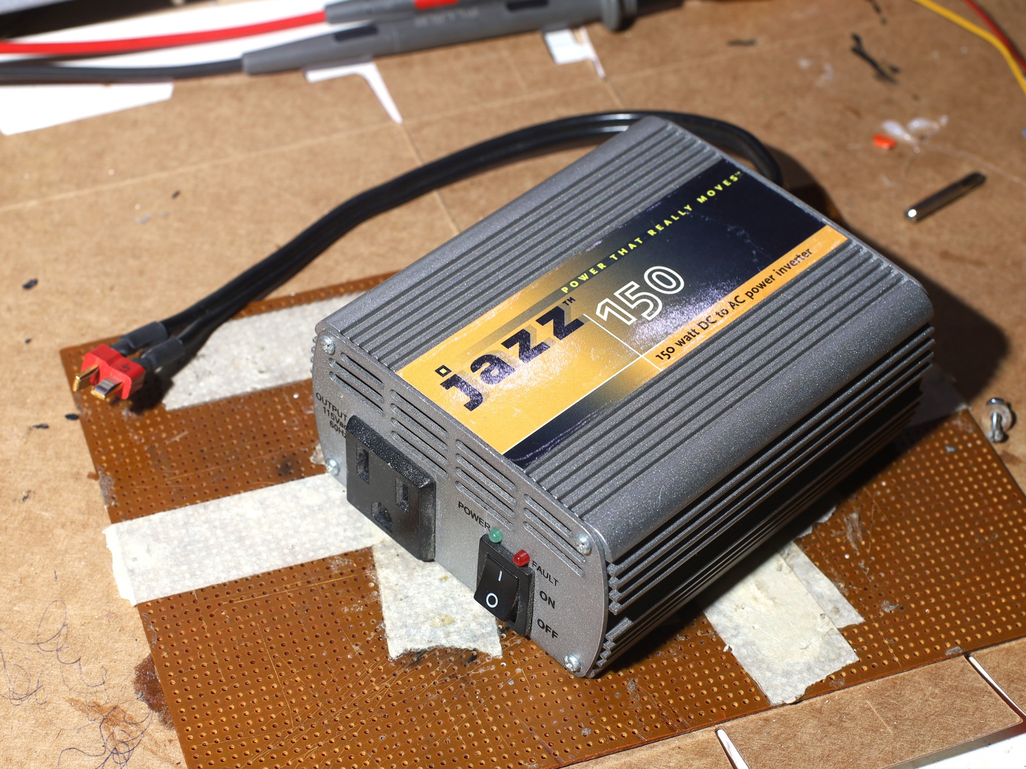
    Note: a true sine wave hack wouldn't work with the Jazz 150 since it would have to peak at 170V.  It probably explodes much beyond 140V.

  • User configurable voltage

    lion mclionhead06/27/2026 at 18:56 0 comments

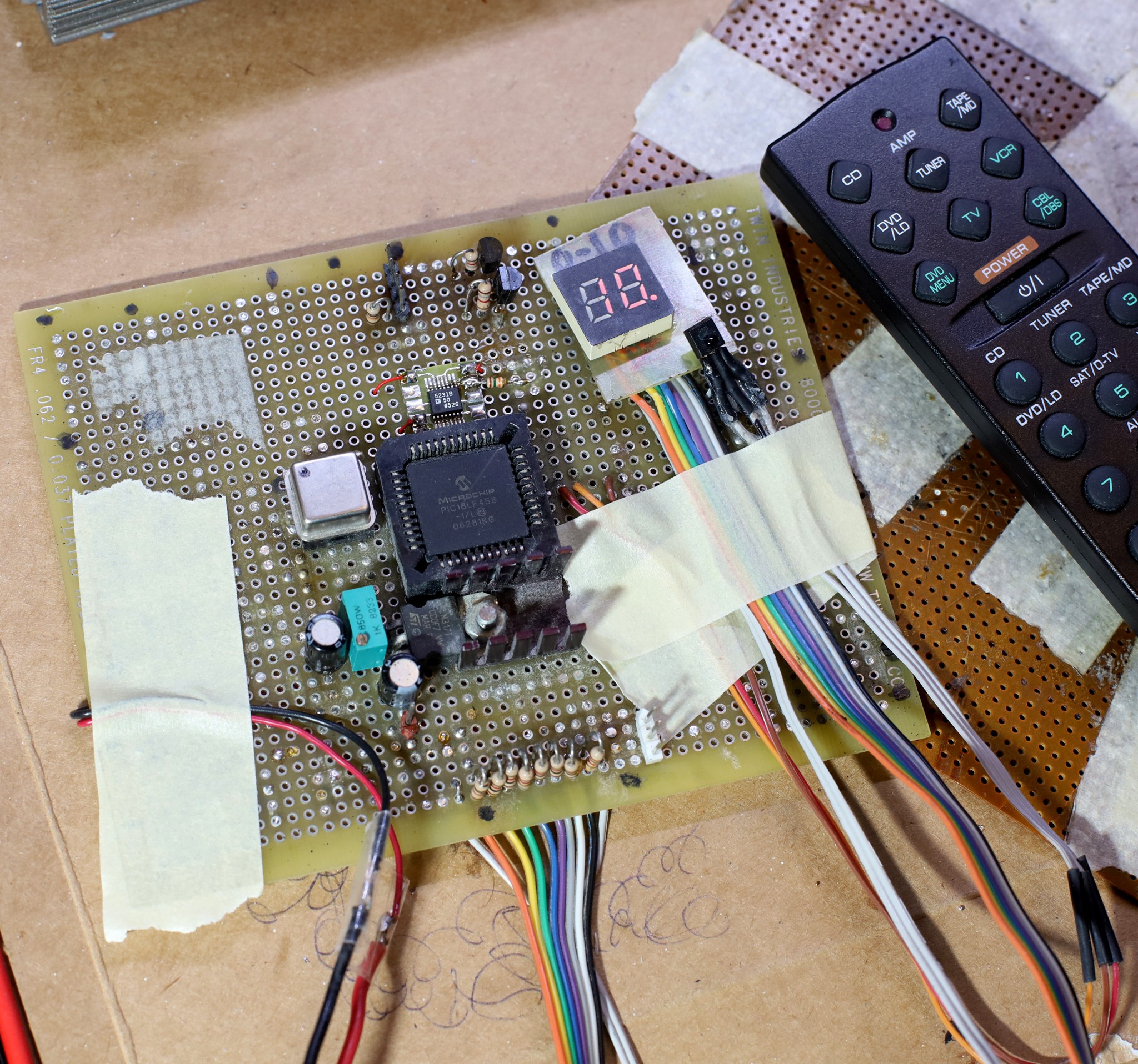
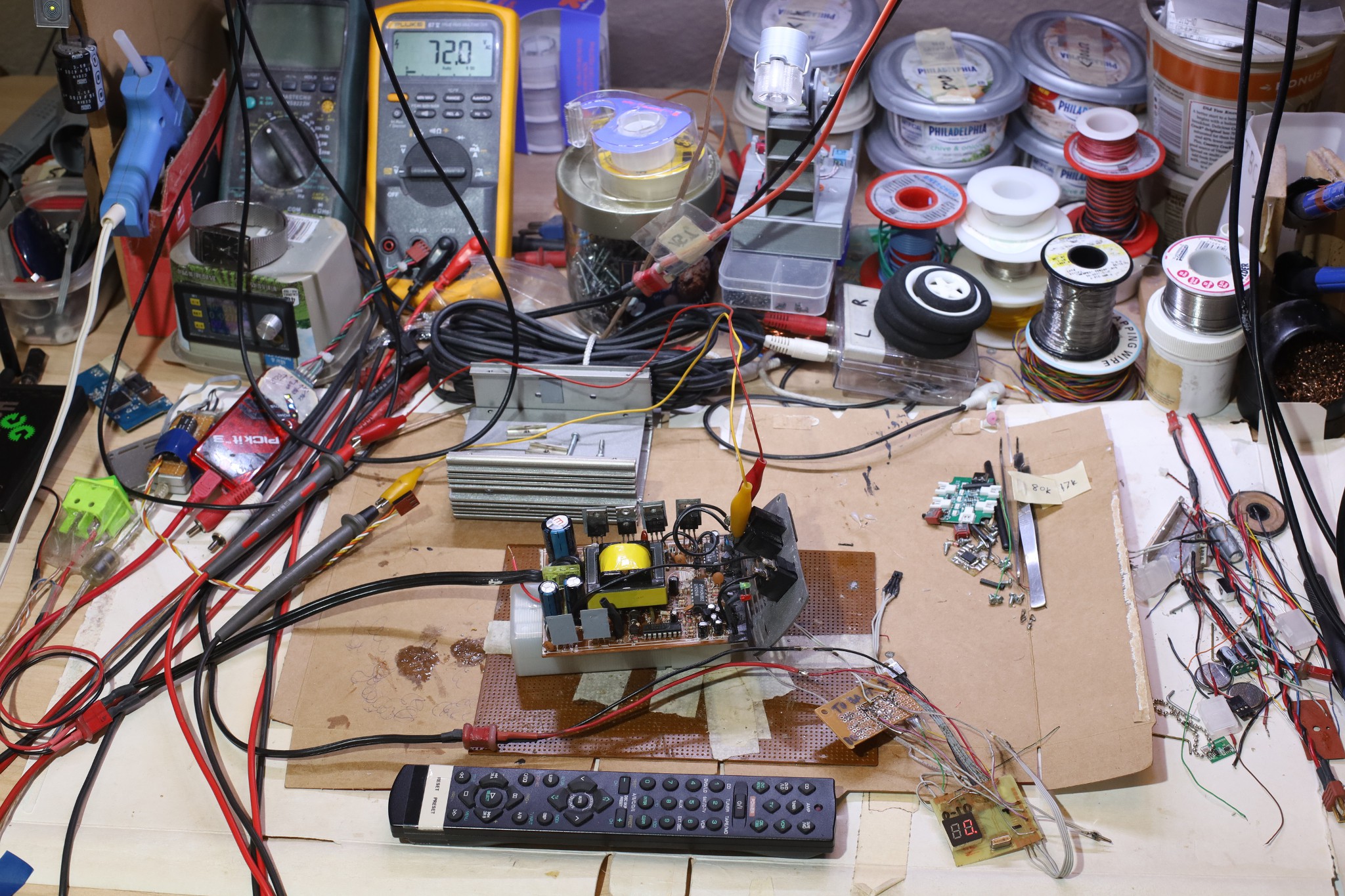
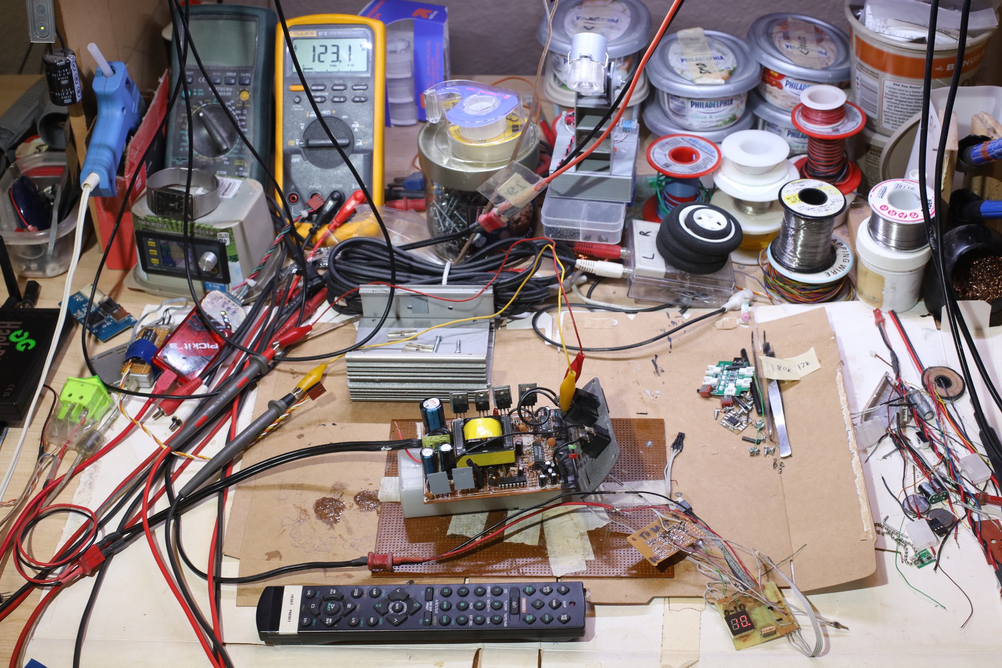
    Got a full voltage adjustment & user interface working with the AD5231 replacing the R9 feedback resistor & an IR remote.  On 12.5V no load, it outputs 72-123V AC.   Channel -/+ dial in 10 voltage settings.  Mute toggles the power on & off by toggling the waveform generator.  The standby power with no waveform is 2W.  R9 is configured to go from 15k - 30k.


    If the AD5231 is unpowered, it's an open circuit & the inverter goes to 123V.  The inverter has a clamping diode which keeps the feedback resistor from blowing up.  R9 is clamped to 15k minimum.

    The maximum output voltage highly depends on the battery voltage & the load.   It goes up to 126V for a 13V battery, but is clamped at 126V above 13V in.  The minimum output voltage stays 72 for all battery voltages.  The resistance range would have to be dialed in with the blower loading it & the final battery voltage.  Lions expect to feed it 14V to try to improve the efficiency.

    It's unlikely a voltage regulator for the brain side would improve matters.  

    The Mastech MS8222H reports 72-130V while the Fluke  shows 72-126V.

    --------------------------------------------------------------------------------------------------------

    The LED lighting used the mighty Mean Well LRS-200-15 because it needed 15V 100W. It goes from 13.5-18V. The inverter goes to 16V before it blows up.  It also needs a fan.

    The LED lighting & inverter could both go in a power rack, but the LED lighting needs a switched input.

  • AC sine wave hacking

    lion mclionhead06/24/2026 at 04:57 0 comments

    The object of the game was getting RMS up to 120V instead of 110 & the blower up to 100W instead of 80.  Waveform hacking on the YC9701 by changing its Vcc pin was a failure.  The next attempt was fixing a sense voltage on pin 4.   That was some kind of .45 - 1.15V active voltage follower connected to a lot of places, an SS8050, an op-amp output, a 10k pulldown resistor R48.  Shorting the pulldown resistor made the duty cycle 100%.  Floating the pulldown resistor made the duty cycle 0.  Halving the pulldown resistor did nothing.  It fed more current until the voltage rose back up.  Fixing the sense voltage to .7 with a diode made it shut down the transformer.  There was unlikely to be a way of dialing in a particular sense voltage.

    The next step was trying to lower the 12V on the entire brain side.  The 12V on the brain side all came through the power switch while the 12V for the transformer all came directly from the battery.  So lower the brain's 12V & you can hack the waveform without reducing the peak AC voltage.  That did absolutely nothing.  It seemed to get the sense voltage directly from the mechanism used to regulate the transformer.

    A home brew waveform generator was the next step.  

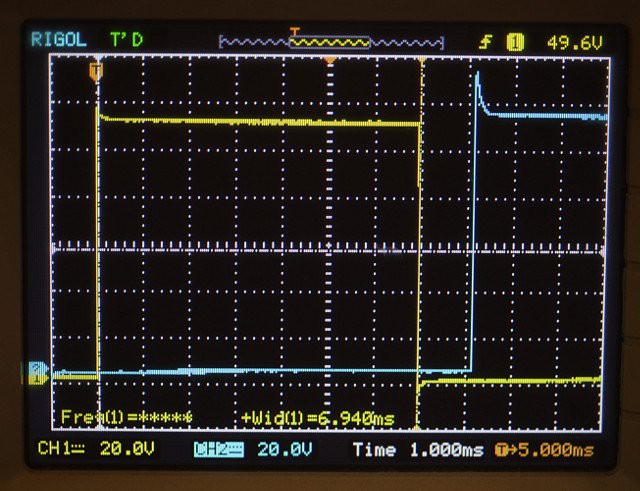
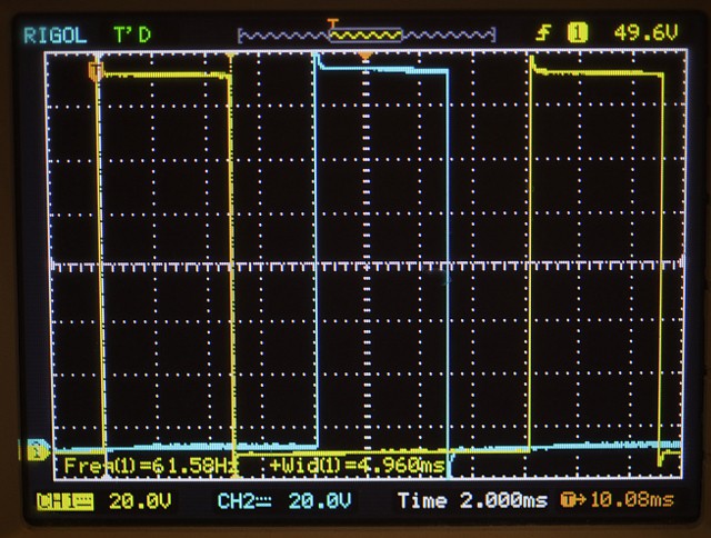
    It's 2 square waves with a 6.94ms duty cycle for 110V & a 4.96ms duty cycle for 130V.  The square waves are offset by 1000/120 ms.  They leave a minimum 1.4ms deadband to avoid a fire after the explosion.

    Resurrected an old board with a small 7 segment display, digital pot, & persistent settings.  Basically, a manual flash from 6 years ago had everything a programmable inverter would need.  It was programmed in assembly in 2020 was a mystery.

    -----------------------------------------------------------

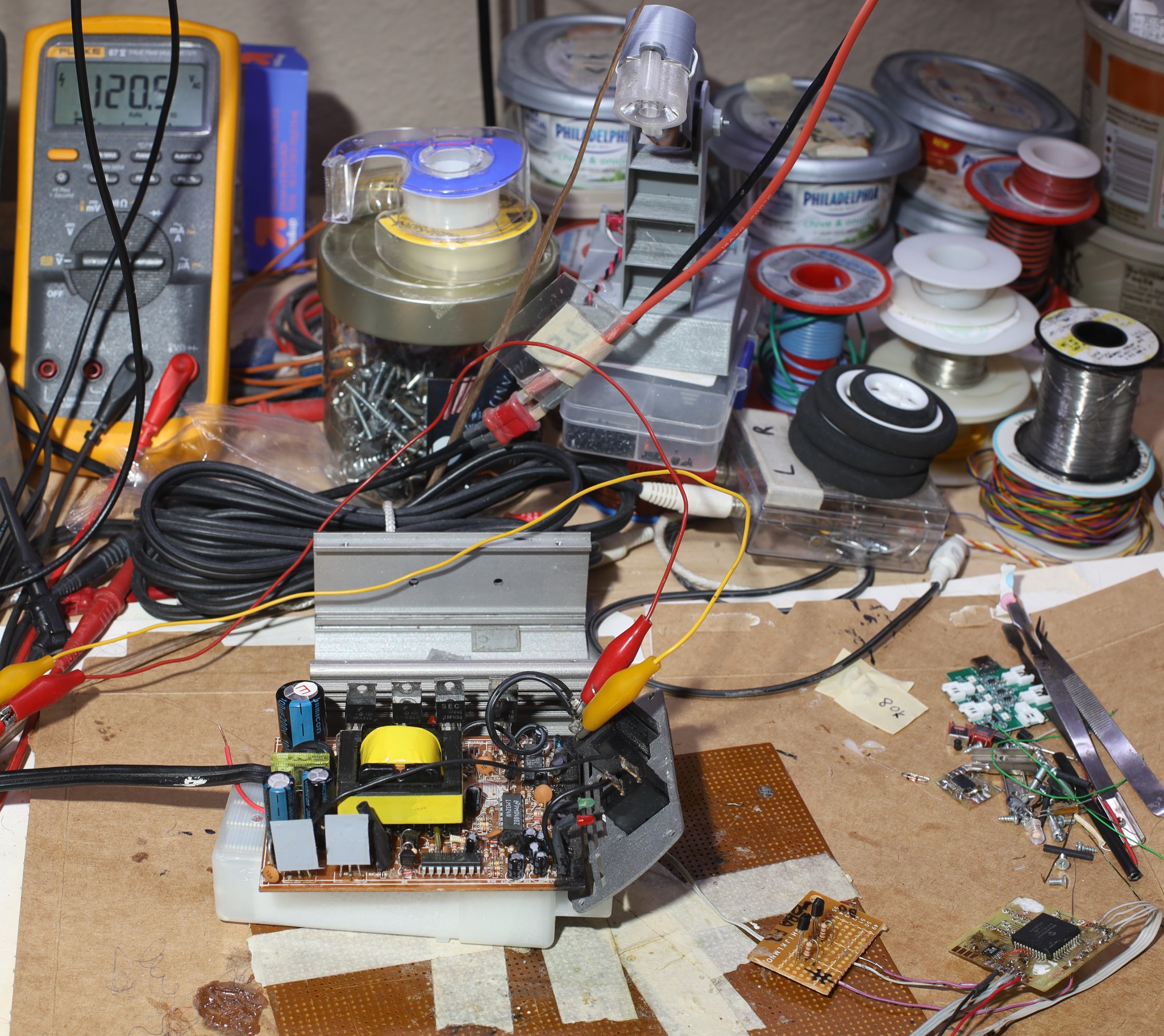
    A BJT thing hacked on the bench got it up to 120V RMS by replacing the 9701 waveform.

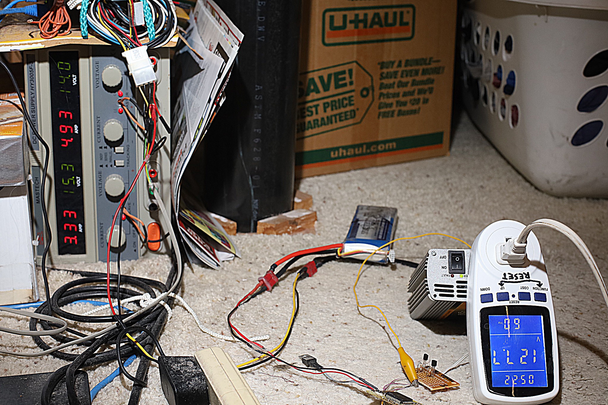
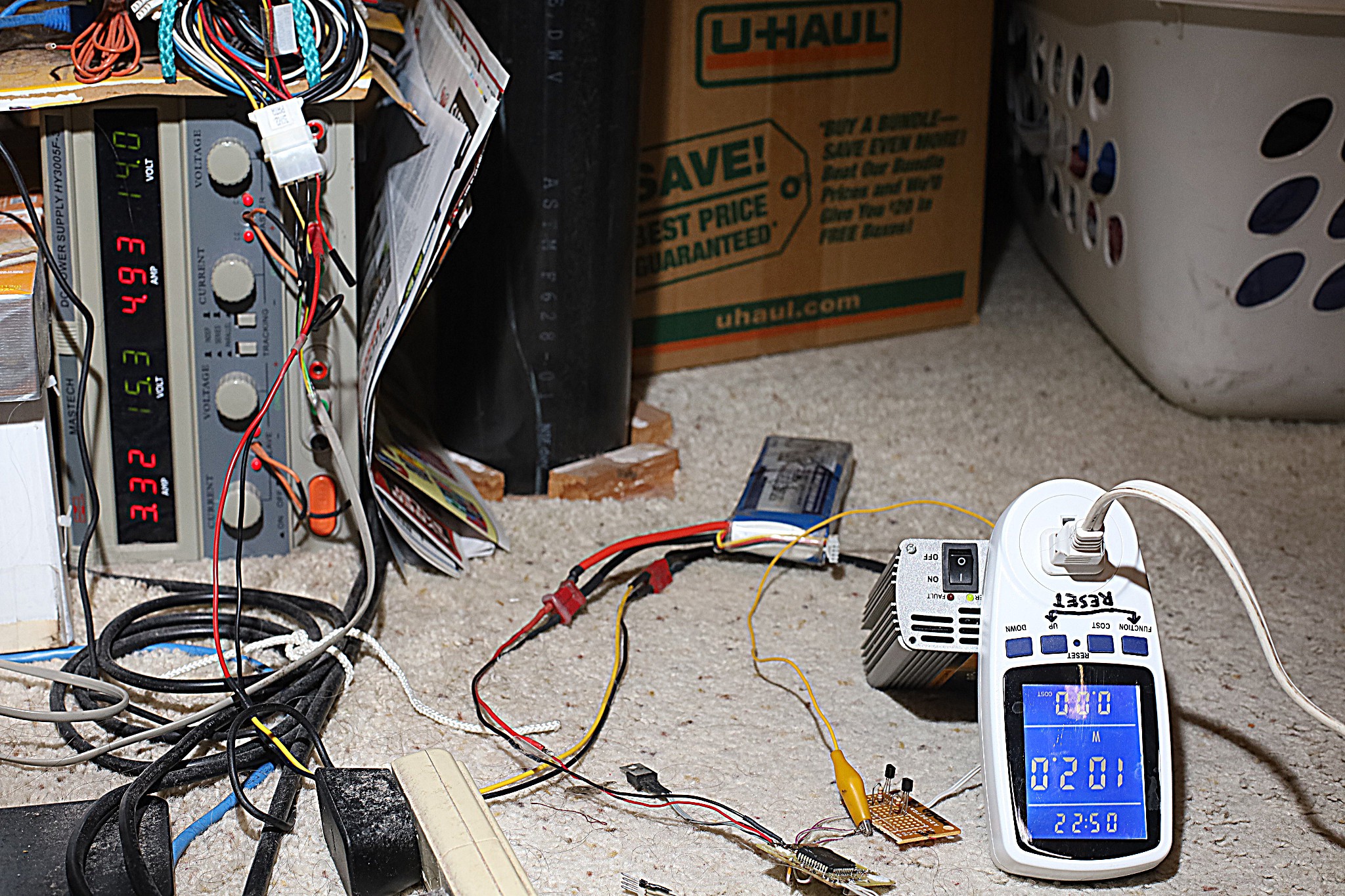
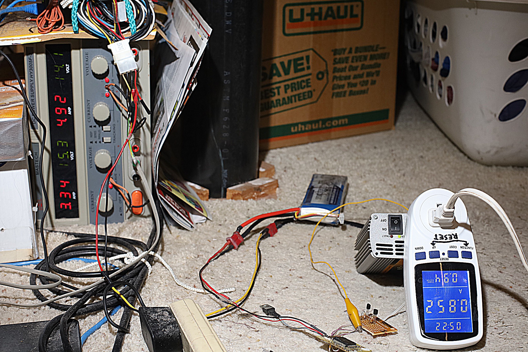
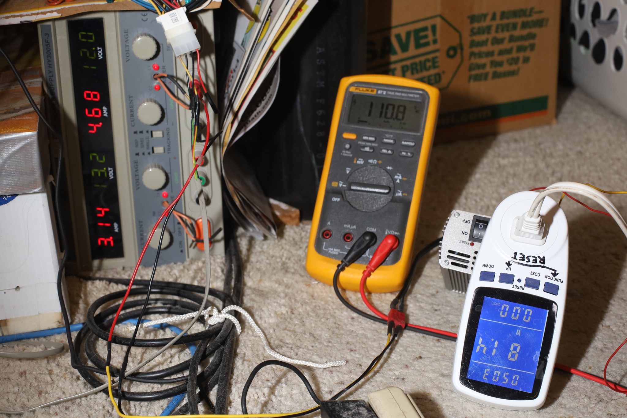
    Powering the blower, it still didn't hit 100W at 120V.  It was 120V 93W .94 power factor

    The square wave was still limiting the power factor.  The PG&E power factor was .97.  

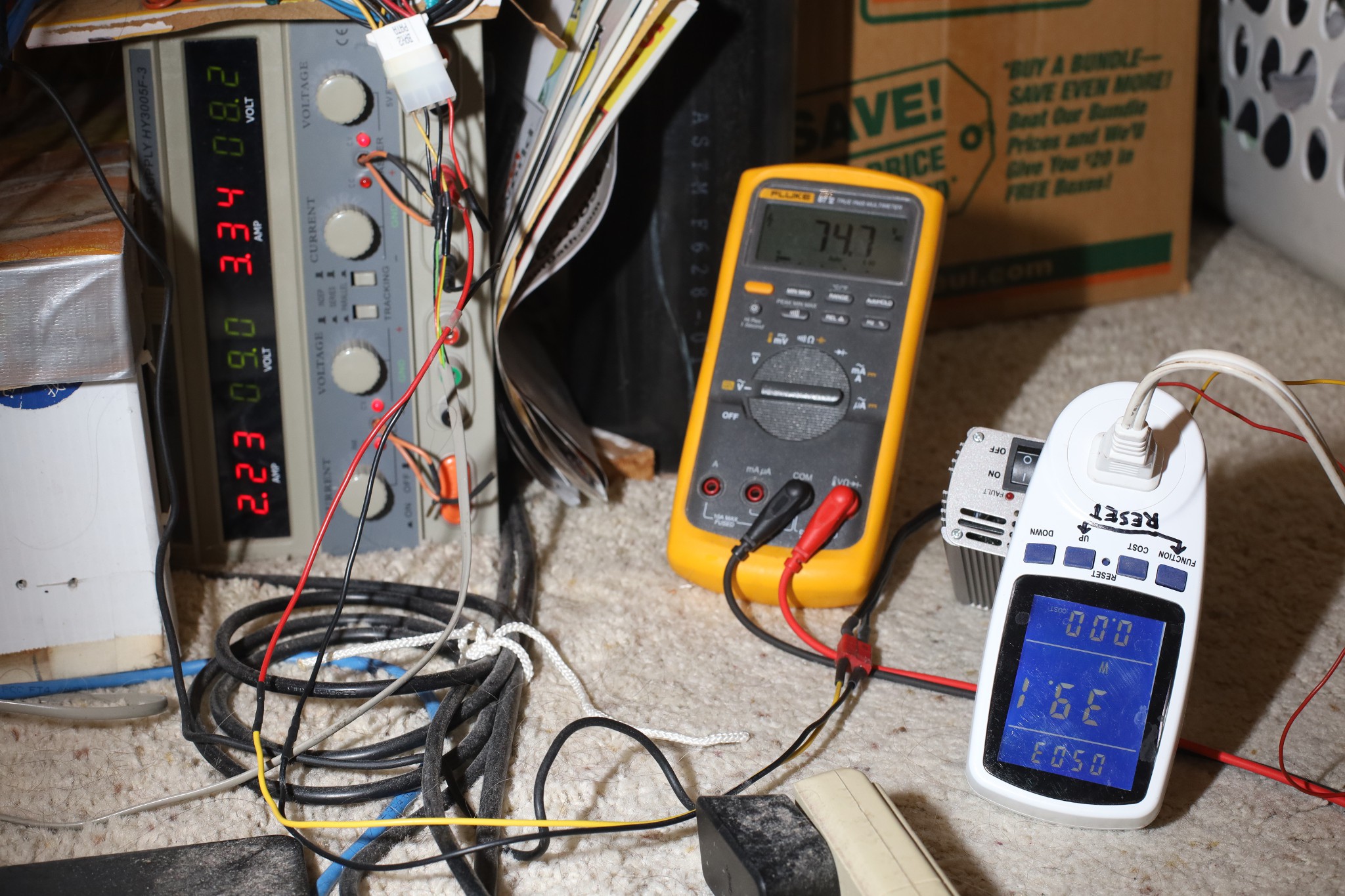
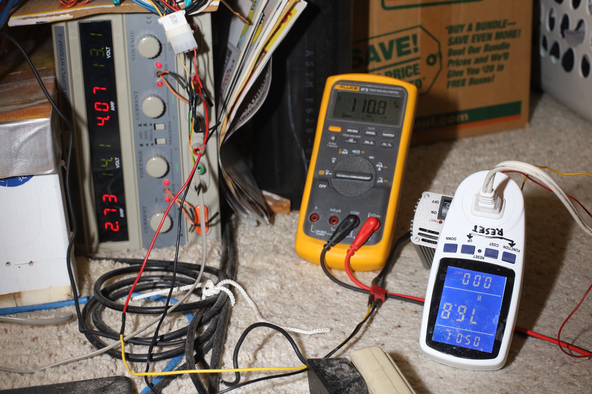
    Kicking the bench up to 14V 8.3A a hair below its maximum, the blower got up to 100W, 127V, .85A, .94 power factor.  The inverter still wasn't getting hot.

    The blower was still a bit noisier on the inverter than PG&E.  Unfortunately, the power was inconsistent on PG&E.  It now used 90W .97 power factor.  It might depend on temperature or it might have been damaged by the 127V.  The inverter now ran it at the same 90W as PG&E when the voltage was 120.

    The inverter had no problem starting the motor.  The trick is the inverter surges above 135V when cutting the motor.

    The next step would be adjusting the inverter voltage using the digital pot instead of the bench.  The trick is preventing the feedback resistor from ending up short & blowing something up.

  • DC Voltage adjustment

    lion mclionhead06/23/2026 at 00:57 0 comments

    An adjustable 5-12V power supply with 10A would be quite expensive & inefficient, so it almost has to run on a fixed 12V, adjusting the voltage in the transformer stage.  The low battery voltage cutoff still has to be left out, to allow it to start a motor.  It still cuts out below 5V, but it seems to be just resilient enough to start a motor when it was hopeless before.

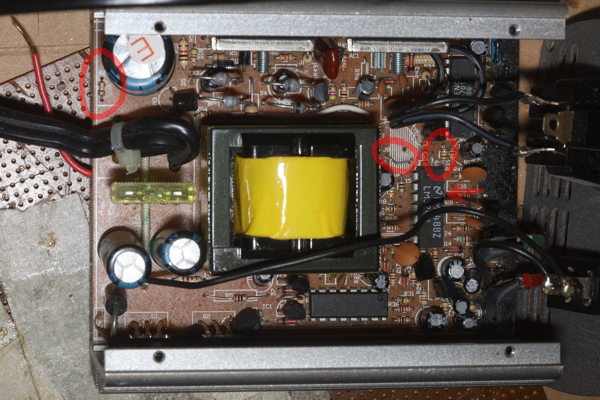
    The feedback resistor network is R2 & R9.  R2 360k & R9 15k divide 140V DC roughly down to 5V.  Reducing R2 or increasing R9 reduces the output voltage.  Then it goes into the LM324.  A digital pot in series with R9 could do the job.  Replacing R9 with a digital pot would risk blowing it up.  Helas, there's now a risk of stalling the motor if the pot glitches.  It almost needs to start at full power, then ramp down.

    So it needs 5.5V for the digital pot & offboard micro, 10V to overclock the YC9701.  Since the inverted waveform is going to be fixed, the battery voltage needs to be limited to limit the inverted RMS voltage.

    In the worst case, the offboard micro could generate the square wave itself.  That would allow it to run at 50Hz, though the frequency comes from an RC circuit near the YC9701.  The final question is the user interface.  It probably needs to capture IR codes & store the setting in flash.  The remote would have up & down but not presets.  It probably needs an indication of the voltage setting.

    Of course, another long desired feature was remote power off.  That would be done by shutting off the 12V side with another MOSFET.

  • The Jazz 150 lives again

    lion mclionhead06/21/2026 at 23:08 0 comments

    Past experience with a cheap dimmer switch was disappointing.  Cheap dimmer switches chop the sine wave, which made motors super noisy.  What's needed for controlling a motor is a full sine wave with variable voltage.

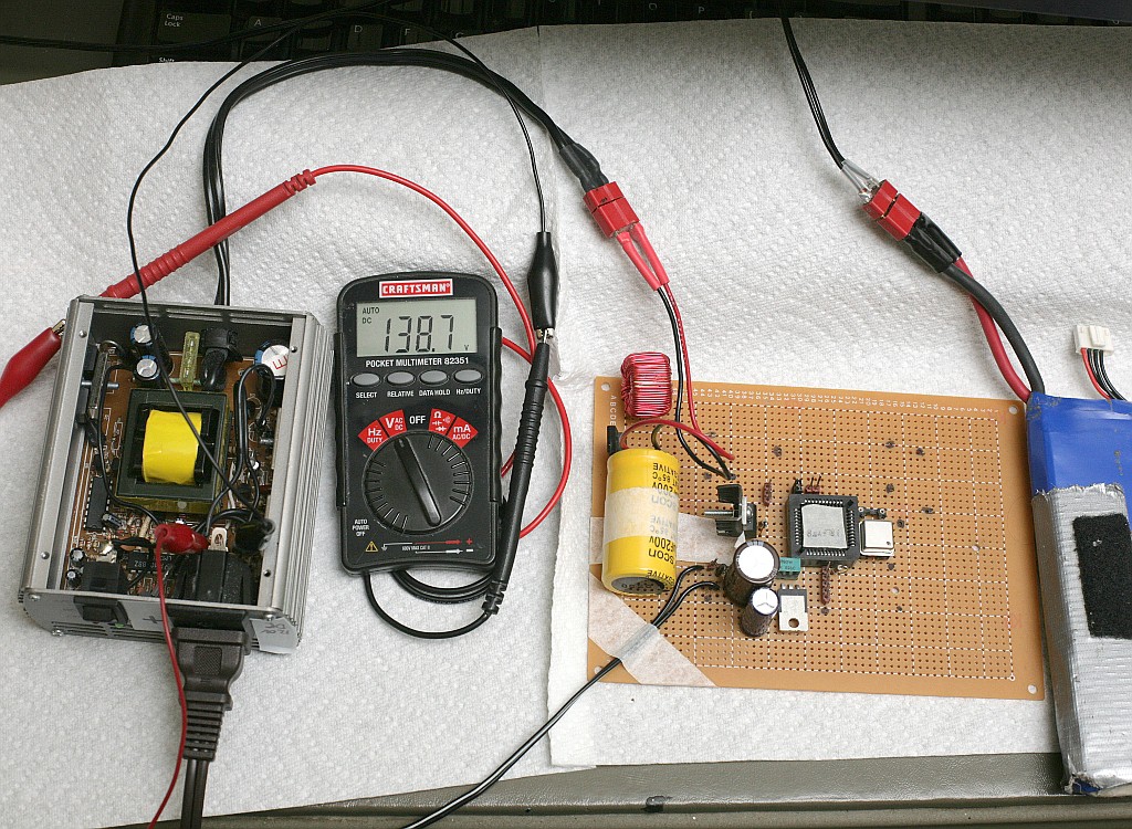
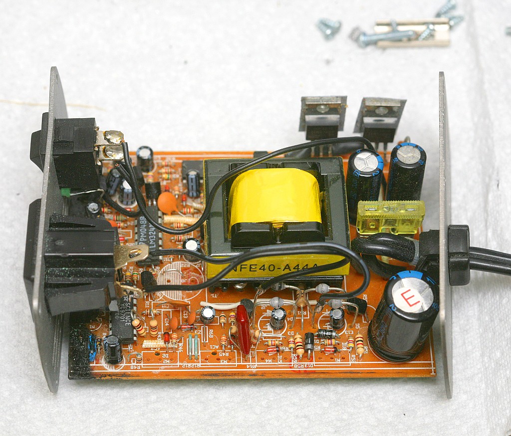
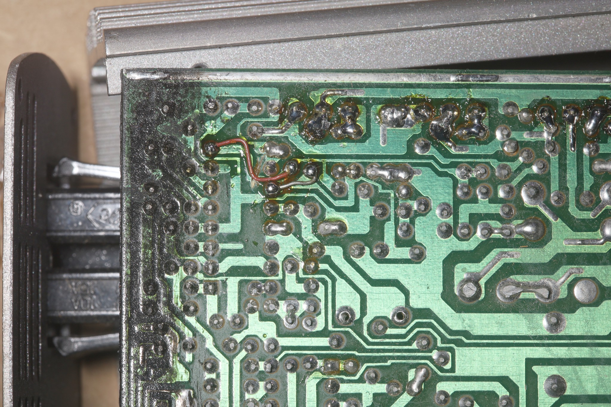
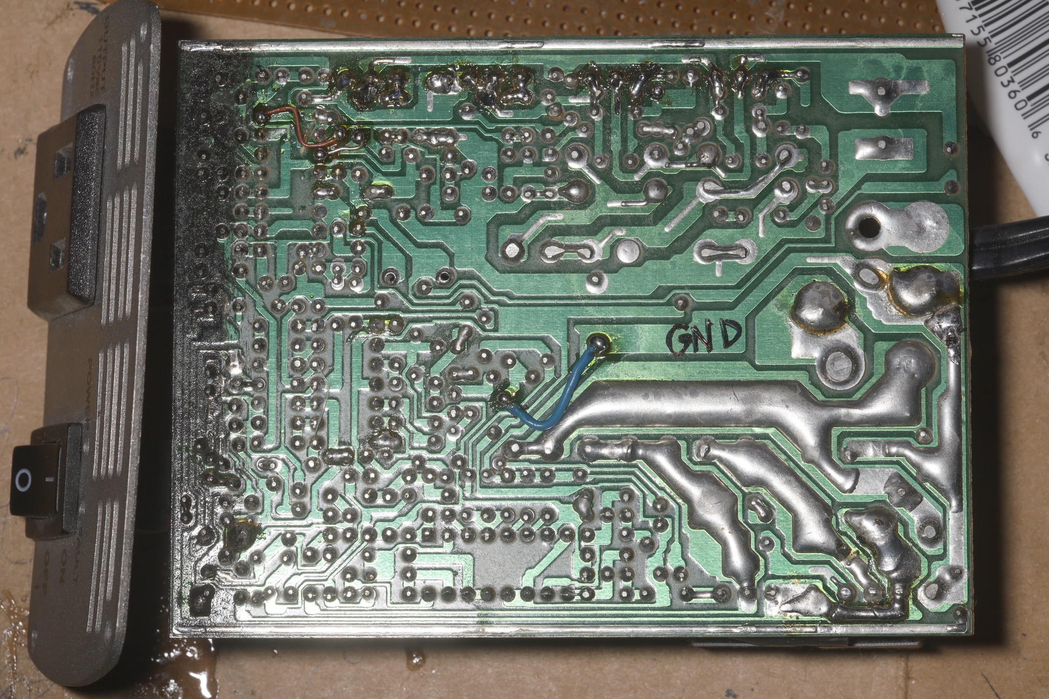
    Revisiting the lion kingdom's junk inverter of 25 years ago, it had some work done in 2011 to output 140V DC from 14V DC.

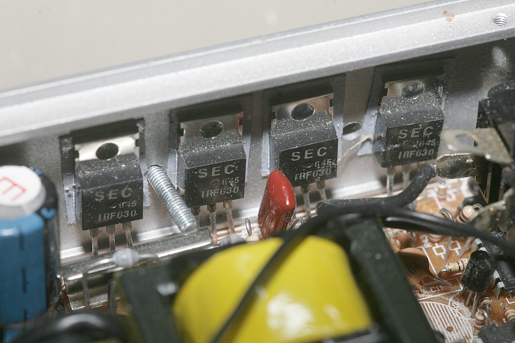
    The inverting transistor gates were severed.

    The inverting transistors were scavenged.

    It originally used an H bridge to generate the sine wave.  It converted the 14V DC to 140V DC in a center tapped transformer, then used the H bridge to make a new sine wave.

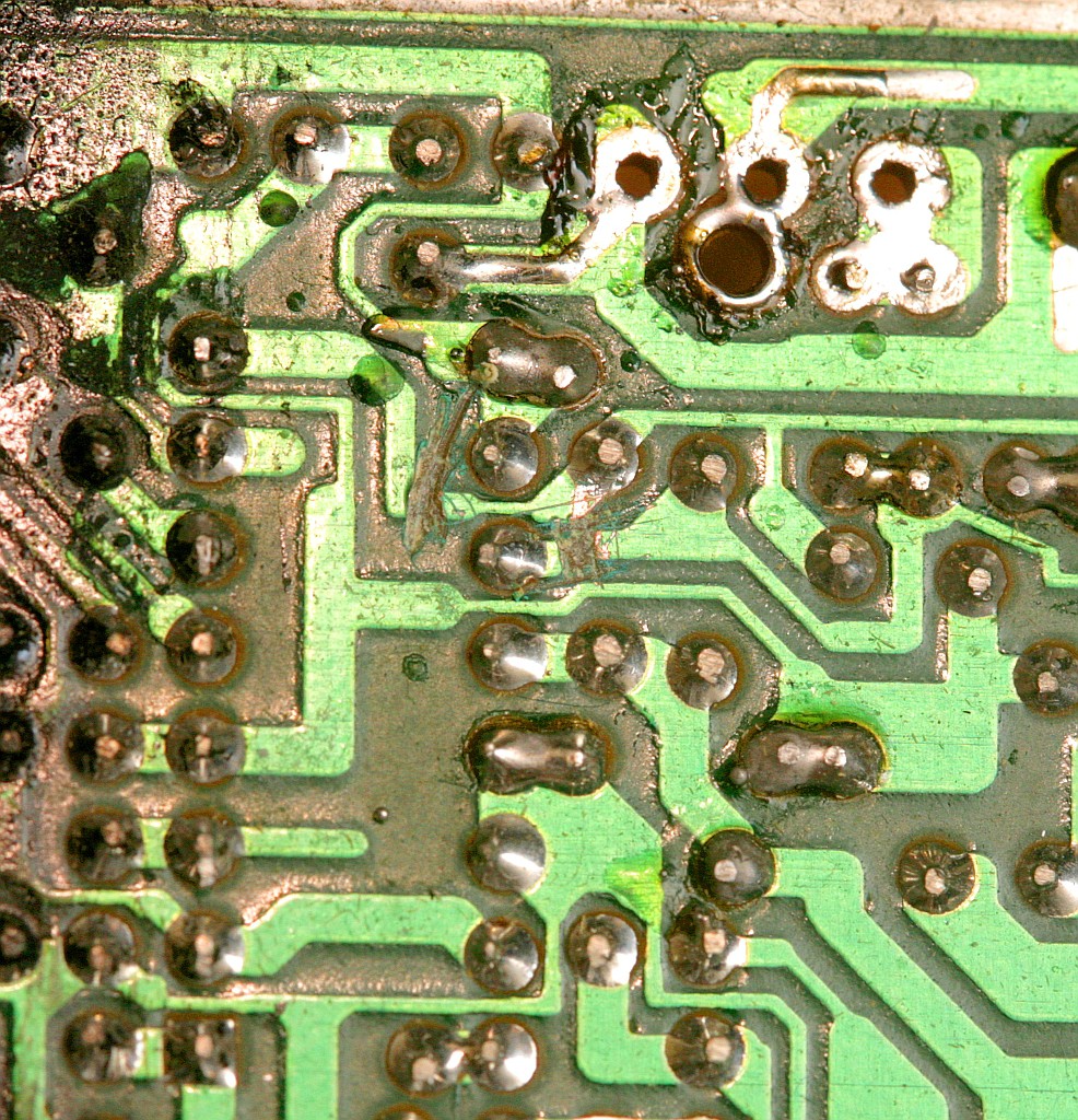
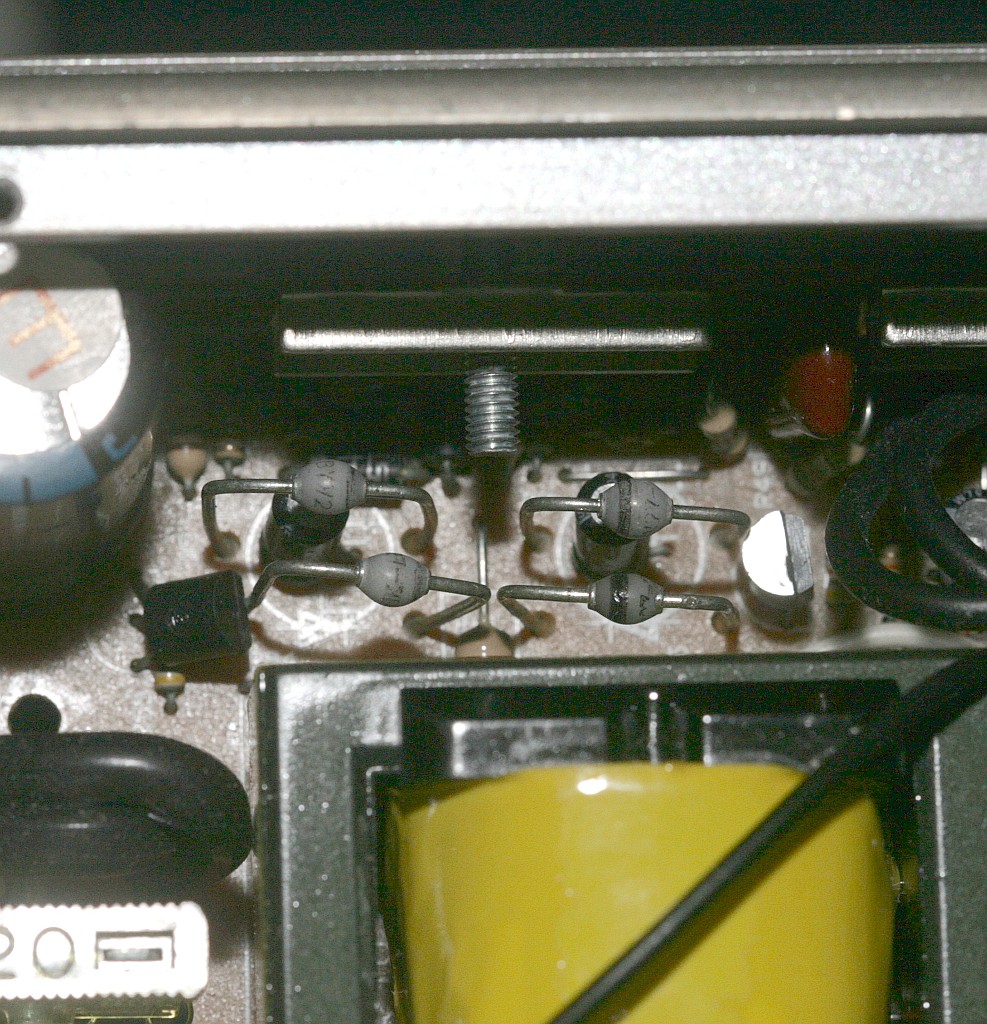
    Helas, some of the MOSFETS & SIL pads were lost.

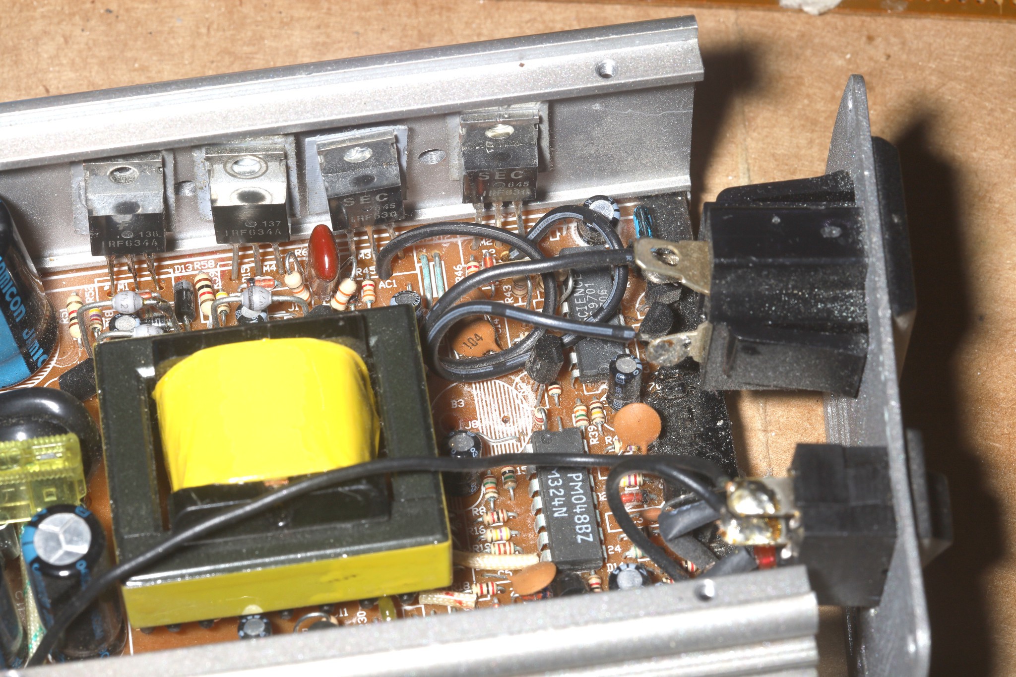
    Some other scavenged MOSFETS went in & the gates were reconnected.  This seemed to work.  

    The output of the inverting MOSFETS is limited to 110V for all input voltages above 11V.  Below 11V, it tracks the input voltage down to 10V.  Below 10V, it shuts down.  It needs at least 12V in to start.  Lions would be ecstatic if it could start & run below 10V.  Amounts above 12V are not needed.

    The high voltage DC side of the circuit was exposed in a rectifier.  It went from 110-140V, depending on input voltage.  It was clamped at 110-140V for battery voltages out of range.  The 1st idea was to make the inverting MOSFETs output a variety of voltages.

    The brain of the operation is the SCIENCE YC9701.  All documentation for it has been lost & replaced by junk AI summaries.  It outputs 2 12V square waves for driving the inverter MOSFETS.  The square wave voltage tracks the battery voltage & its duty cycle varies.  The off time is when the MOSFETS are on.  The lower the voltage, the longer the off time.  The higher the voltage, the shorter the off time.  The duty cycle is bounded so above a certain battery voltage, it's limited only by the DC side.  Below a certain battery voltage, it follows the DC side down.

    The square wave seems to be generated by comparing a fixed sawtooth to the battery voltage.  The sawtooth fires at 120Hz so the 9701 takes care of alternating polarity.  If the 9701 always gets 7-10V, it should generate the maximum duty cycle for all battery voltages.  Below 7V, it gets unstable.

    The inverted output is a square wave instead of a sine wave. 

    Another option is replacing the MOSFET gate voltages with an arbitrary square wave generator.  Unfortunately, the output is the same as a cheap dimmer switch so motors would be unpleasant sounding.  Generating a true sine wave this way would be quite inefficient.

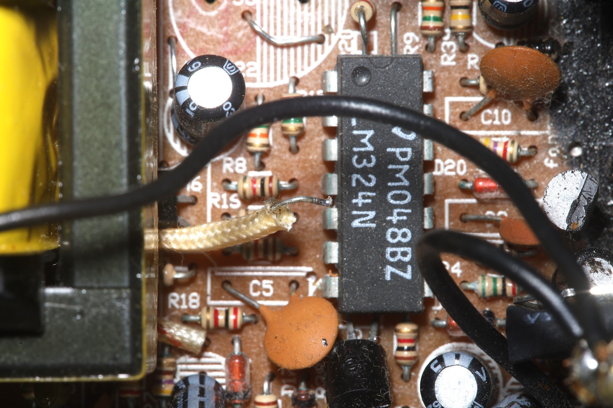
    The easiest route would be defeating the low voltage shutdown, involving quite a bit of reverse engineering.  It's probably getting cut out by the LM324.  Pins 1 & 7 are strict comparators, comparing a battery voltage on - with a 5V reference on +.  Pins 1 & 7 go to 12V when the battery is low & go to GND when the battery is high, with hysteresis.  Pin 14 & 8 are for something else.

    It could be intended as a fuse, which would make it dangerous to disable.

    Popped out the biggest wire & grounded it which actually got it to stay on below 10V.  Got it to generate 60V-110V.  It shuts down below 5V input because the brain needs 5V.

    Noted the blower didn't go quite as fast on 110V as manes & it made a humming noise.  Adjusting the battery voltage adjusted the blower speed.  It would go down to 8V before the motor stalled.  The maximum blower speed was 12V battery voltage.

    Going from 12-14V, output amperage decreased, output voltage stayed the same, & the output power decreased from 80 to 76.  The hum got louder.  Power factor was a constant .94.  It was an artifact of it adjusting the duty cycle to compensate for higher voltage.  The highest power transfer came from a 12V battery.  The Jazz150 didn't...

    Read more »

View all 7 project logs

Enjoy this project?

Share

Discussions

Does this project spark your interest?

Become a member to follow this project and never miss any updates