iliasam
-
Assembling LIDAR mechanics
08/06/2017 at 18:10 • 0 commentsFirst step is building "main plate" - it is the part that holds ball bearing, motor, and some other parts. This part can be cut from some flat plastic plate. I have used 5mm acrylic glass:
![]()
Drilling 42 mm hole for bearing was a little tricky.
This part can be printed at 3D printer.Next step is assembling everything.
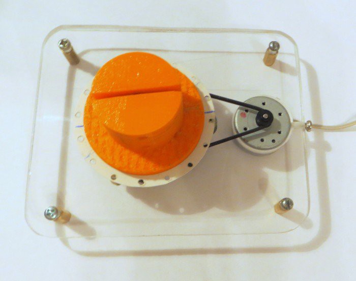
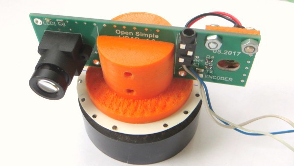
Photos of assembled mechanics (top view):
![]()
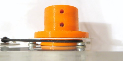
Side view:
![]()
Motor is connected with the PCB holder with rubber belt.
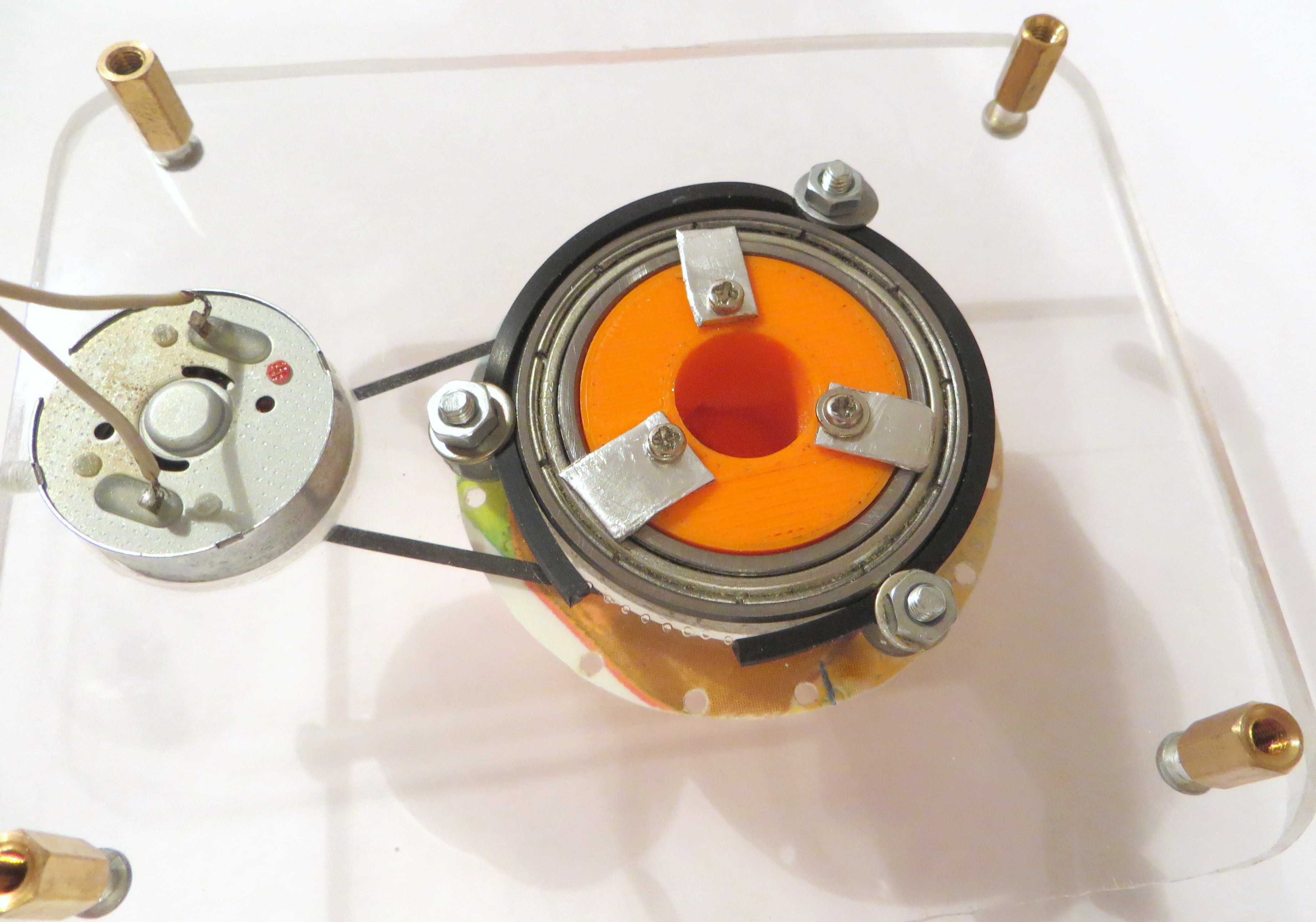
Down view:
![]()
Here it can be seen method of fixing the PCB holder to the ball bearing.
Next step is to fix encoder at the "main plate" and to test it.
-
PCB holder
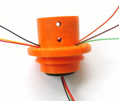
07/30/2017 at 12:31 • 0 commentsI have printed special holder for PCB. This holder will be rotated by motor.
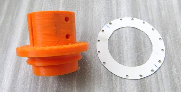
Here is a photo of it:
![]()
The right part is encoder disk.
PCB holder don't have holes for slip ring wires, so I have to drill two.
Here is a photo of the PCB holder with the slip ring installed in it:![]()
Photo of PCB placed to holder:
![]()
Encoder disk is glued to the PCB holder.
-
PCB is assembled
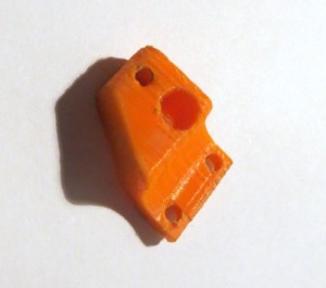
07/29/2017 at 18:11 • 0 commentsAt this step I have printed at 3D printer laser holder. This small part is used to hold the laser at certain position.
Photo of the laser holder:
![]()
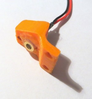
I glued laser to the holder with hotmelt.
Photo of the holder with the laser installed:![]()
Last step is to fasten the laser holder at PCB. It's done with two M3 screws.
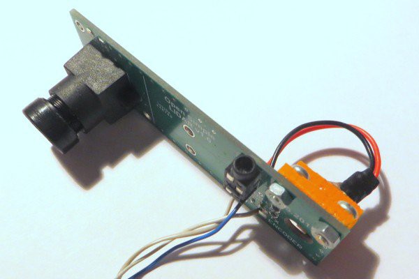
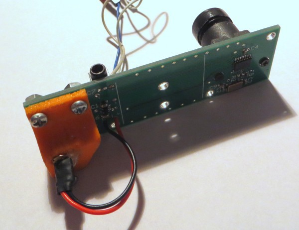
Photos of assembled PCB:
![]()
![]()
Angle between the laser and the lens axis is specially calculated. It must be near 11-12 degrees.
Optical alignment.
To get the LIDAR properly working I need to align it's optical elements. First step is focusing lens. Focusing is done by rotating the lens till the image in PC utility don't became fine.
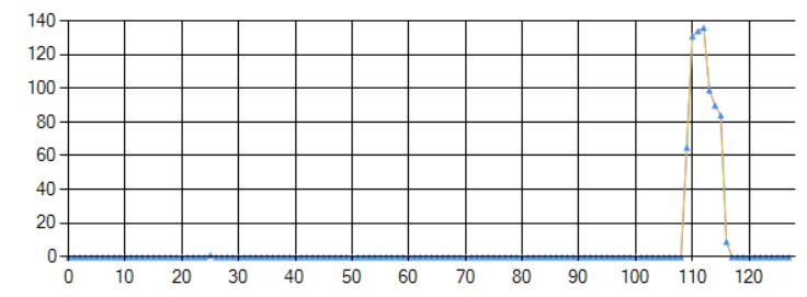
Photo of not focused image:
![]()
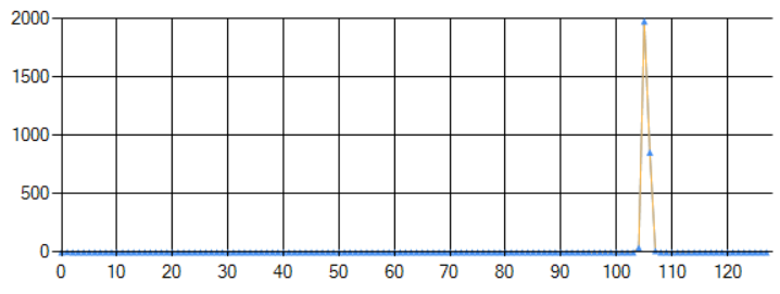
Photo of focused image:
![]()
When the lens is set to best position it must be fixed by special screw which is twisted to the lens holder (it must be special hole in it).
Next step is laser alignment. It is done by special screw than must be placed at lower hole of laser holder. The purpose of laser alignment is to get best amplitude of received signal. This alignment must be done at maximum LIDAR's distance (3-4m).
-
Programming and first tests
06/30/2017 at 11:00 • 0 commentsI have tested all PCB electronics, and everything is forking fine, so I can start to program MCU.
I have working code for my previous lidar - it was based on STM32F100 and TSL1401.
So I take code from that project and ported it to new STM32F030 MCU.
At first step I write testing firmware that capture analog signal from sensor to MCU memory and then transfer it PC by UART.
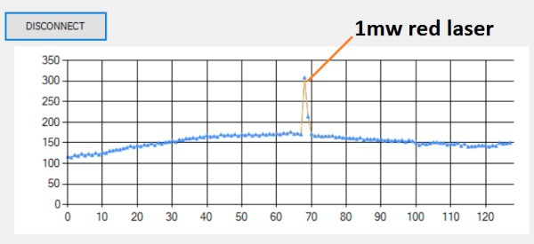
I write PC utility that draw illumination level of 128 sensor's pixels:
![]()
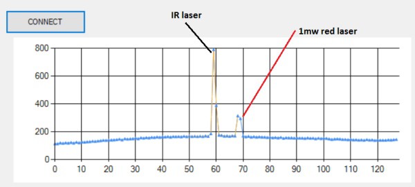
Here is a picture with IR laser that I want to use in final design:
![]()
The distance to object (white wall) was near 1.8 m.
The next step is printing laser holder and mounting it at PCB.
-
Electronics Assembly
06/20/2017 at 15:26 • 0 commentsFinally I get all electronic parts, so it's time to assemble PCB!
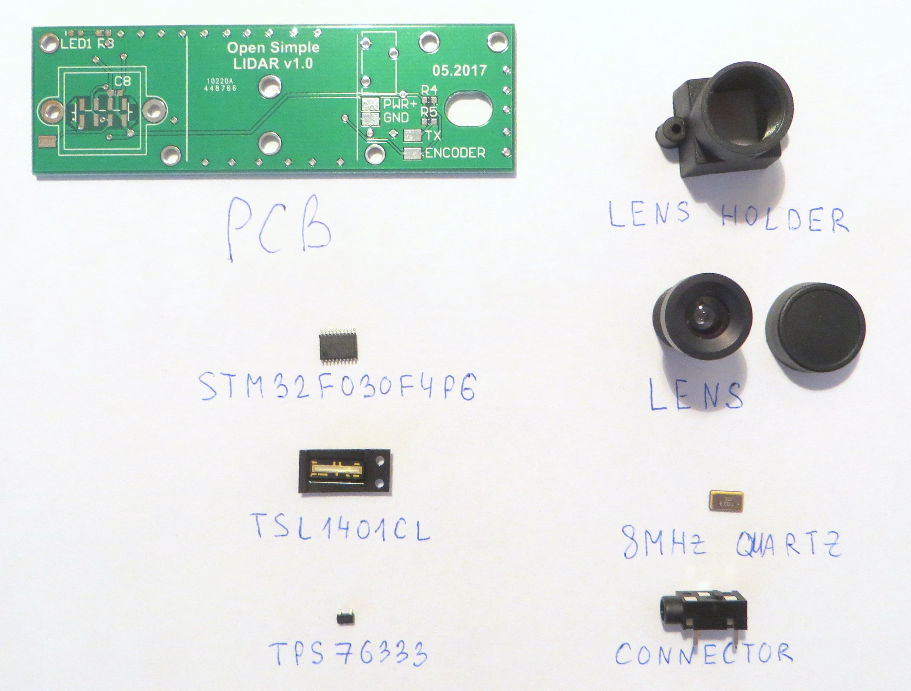
Photo of components used:
![]()
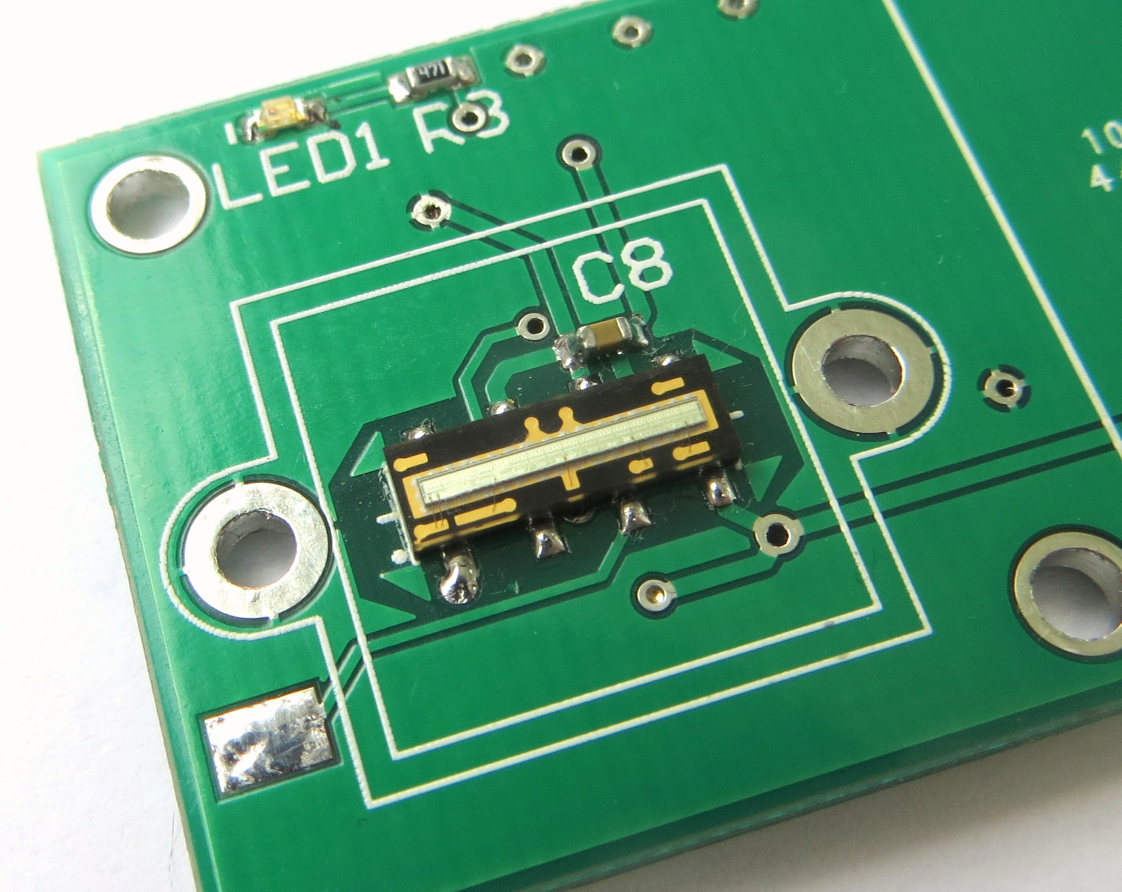
Most of them are easy enough to solder. The exception is light sensor - TSL1401CL; because pads of this sensor are placed under it's body.
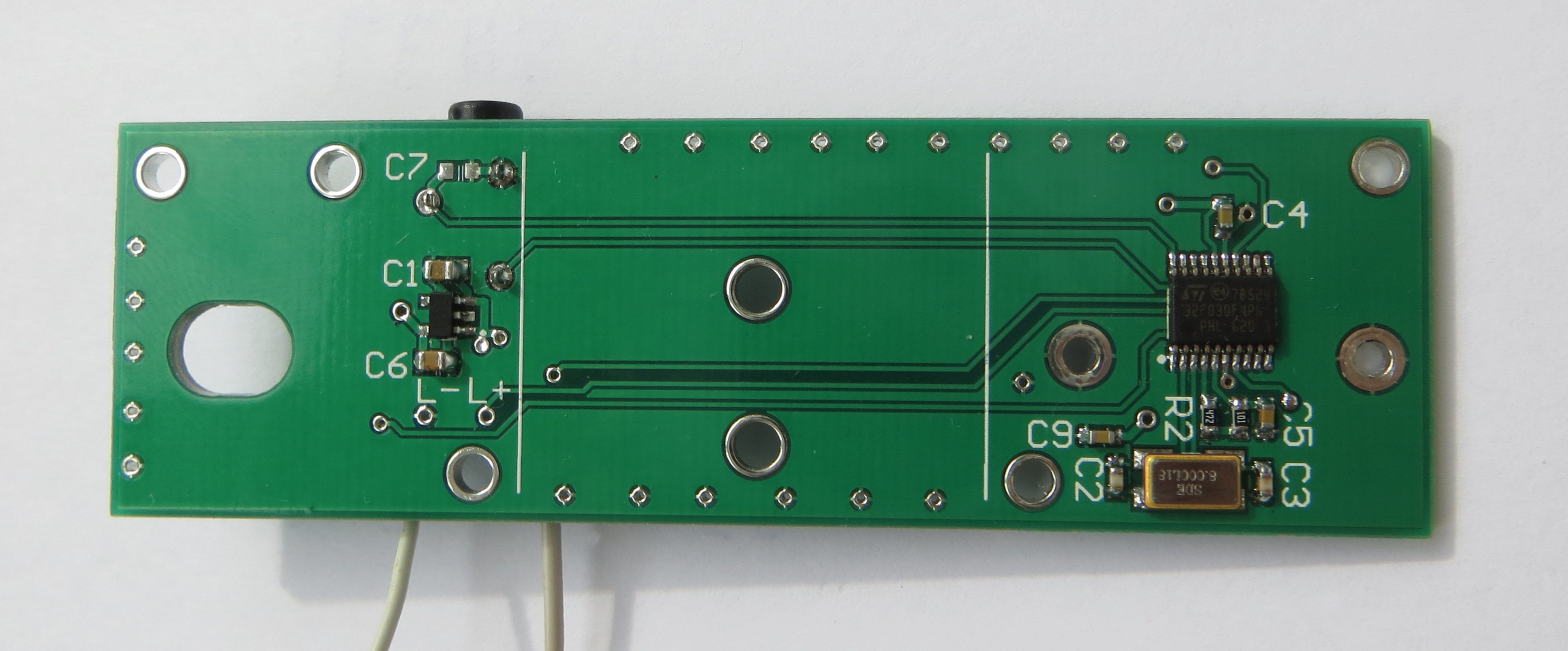
Photo of assembled PCB:
![]()
Close view of soldered TSL1401:
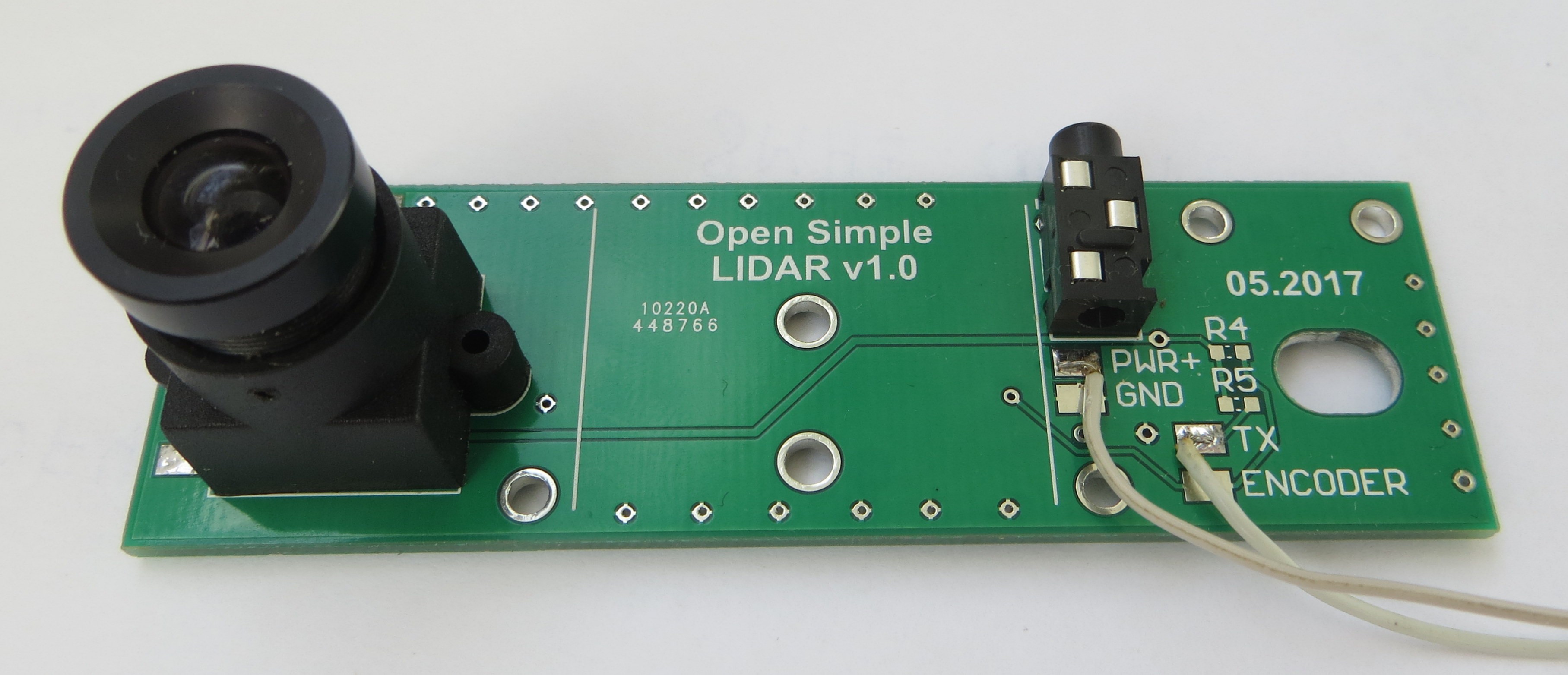
Photo of PCB with leans installed:![]()
![]()
3.5 mm Jack connector is used for STM32 programmer connection.
ST-Link utility found STM32 - so the next step is it's programming.
Firstly I need to run capturing data from light sensor.
P.S. I have updated Github files - I added some models, PCB schematic, gerber files.
-
Small model update
03/30/2017 at 19:12 • 0 commentsNow I found suitable encoder sensor for my Lidar - it is RPI-352. It can be bought at aliexpress.com or digikey.com.
I have added encoder ring to the model. I think that this ring must be metallic and have 15 drilled holes for light from sensor.
Encoder is important part of Lidar, it used to detect zero angle crossing and for rotation speed calculation.