svofski
-
Wrapping up
09/10/2026 at 19:48 • 0 commentsSplit flaps make for a pretty sight so here's a video.
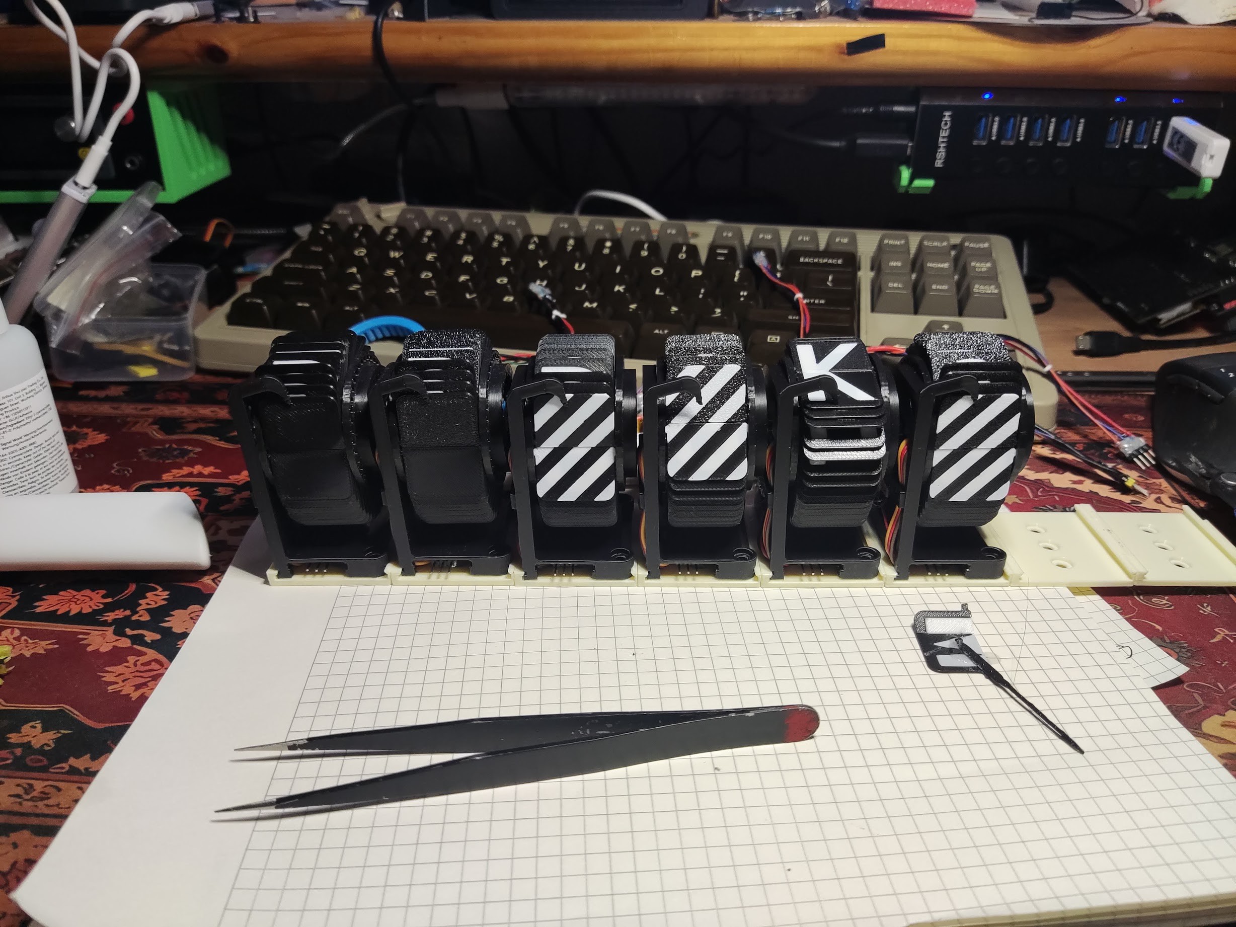
This pretty much wraps the project. Maybe I can make small improvements regarding reliability or put it in a nice box, but nothing revolutionary is going to happen to it at this point.
Summary
Good
- Success
- I managed to make them pretty compact
- they are as fast and noisy and and as fun to watch as I expected
- cheap 360 degree servos are usable
- I like the overall design that I ended up with, it's fairly elegant with absolute minimum of extra parts
- no custom PCB required
Not so good
- optical sensor could work better
- the reliability is far from clockwork-like, they can go nuts
- no custom PCB means a lot of time wasted on soldering the wires
There are a few factors that I think contribute to somewhat variable quality of this entire contraption.
1. These 360 servos are by definition hacks, factory provided but hacks. Each motor is slightly different, some buzz happily, others seem to struggle at the same speed setting. But this is easy to compensate in software.
2. The 50Hz PWM control puts a hard limit on the maximum speed you can use while still being able to stop exactly where needed.
3. There is some inevitable play in how QRE1113 sensor is placed. Also the contrast between black and white markers on the code wheel is not ideal. The human eye sees them as black and white, but the IR phototransistor in QRE1113 likes white acrylic paint much better. The lack of contrast imposes tighter requirements on the tracking algorithm.
4. There is no quadrature sensing and we can't tell direction of rotation. If the drum shakes a tiny bit while in an inopportune position it can be understood as forward movement by the algorithm. I suspect that the flaps flipping can be a significant source of shakes that could be affect neighbouring units.
What I think could be done better with infinite time and patience
1. Custom PCB with CH32V003 and QRE1113 will reduce build time and stress dramatically and make building displays with larger character count feasible.
2. Sensor tracking is pretty simplistic and probably can be improved even without any hardware modifications. But the lack of quadrature sensing is still an important limitation.
3. Perhaps a white plastic with better IR reflectivity, or even a sticker could be used to improve contrast and to make sensor reading more authoritative.
4. Sacrificing a few characters could make it better. For example "1", "0" in Aston2 are identical to "I" and "O". Dash/barberpole is also not really a necessity. That's 3 flaps less, slightly larger ticks marks for the sensor to sense.
-
10 units
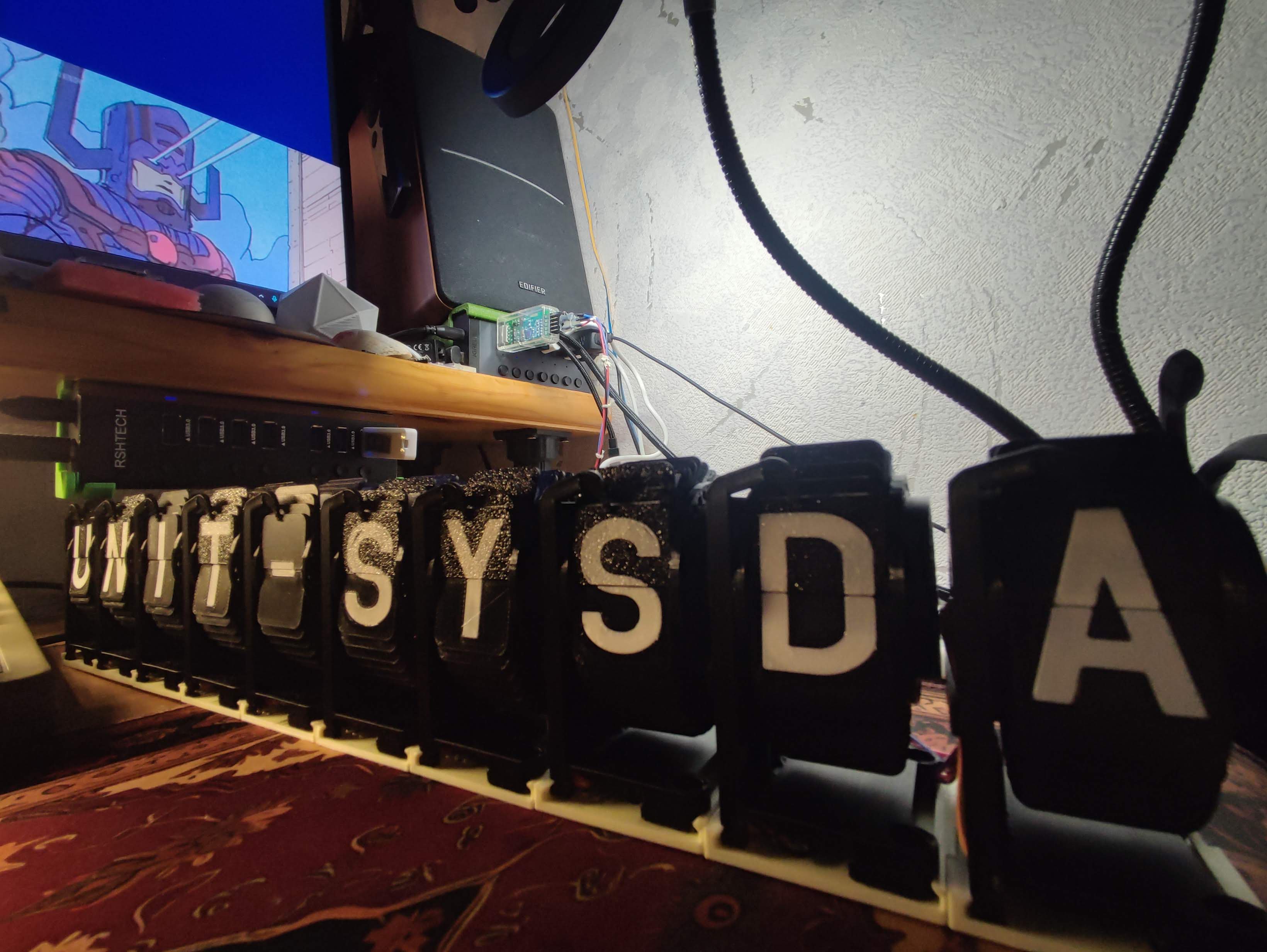
09/03/2026 at 22:57 • 0 commentsFinished the last 4 units tonight, making it 10 units total.
![]() I guess that's it. Definitely do not want to build more.
Going one by one with 10 characters is painfully slow so I tried to implement power budgeting. 3 at once for homing, 2 for typing. Nice when it works, but less reliable than displaying one character at a time. Clearly either there is not enough juice, or there is some cross-talk. FWIW it could be even mechanical cross-talk. -
Exciting bits
08/30/2026 at 17:28 • 0 commentsPrinted new wheels using slightly wet filament and had a couple of minor defects in the white ticks so I touched them up using white acrylic paint. Thought nothing of it, didn't even take a picture.
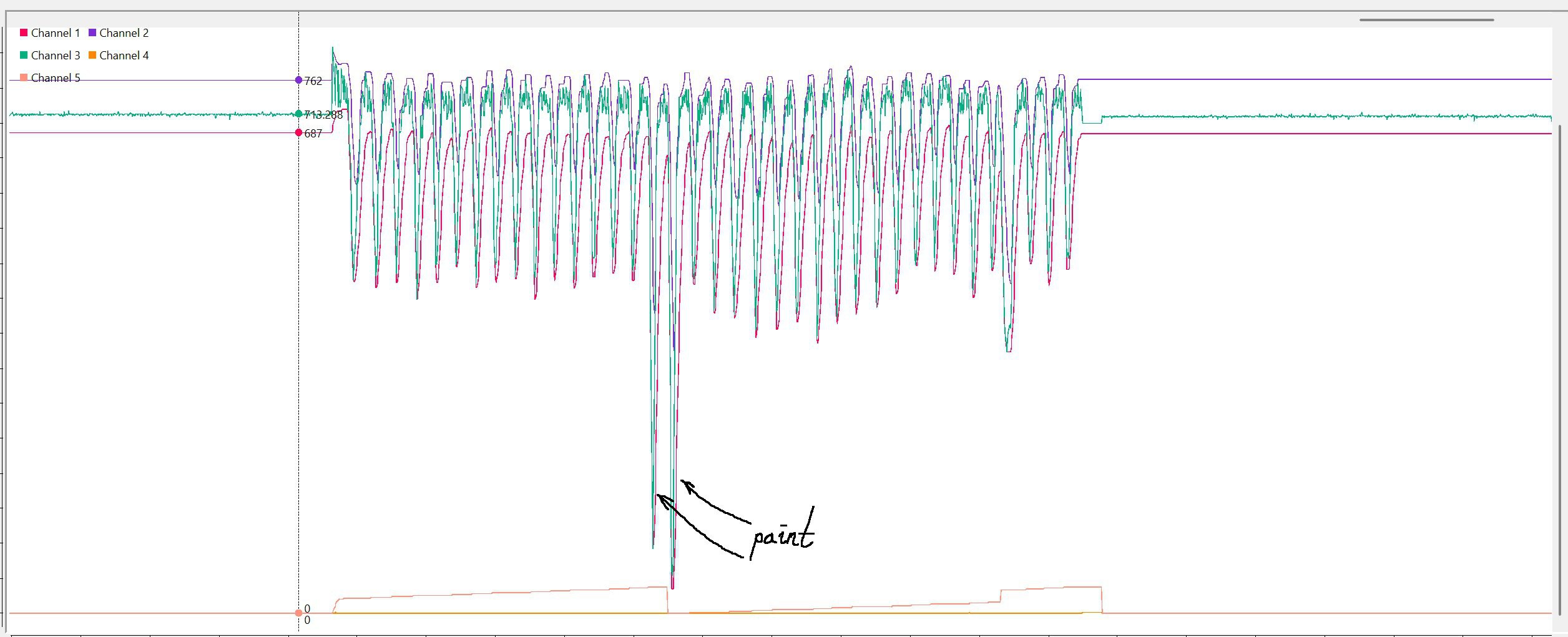
Here's what sensor reading looks like when passing the touch-up points:
![]()
This is a great contrast and I would like to have it for all tick marks, but unfortunately my white filament seems to be rather dull from QRE1113 point of view.
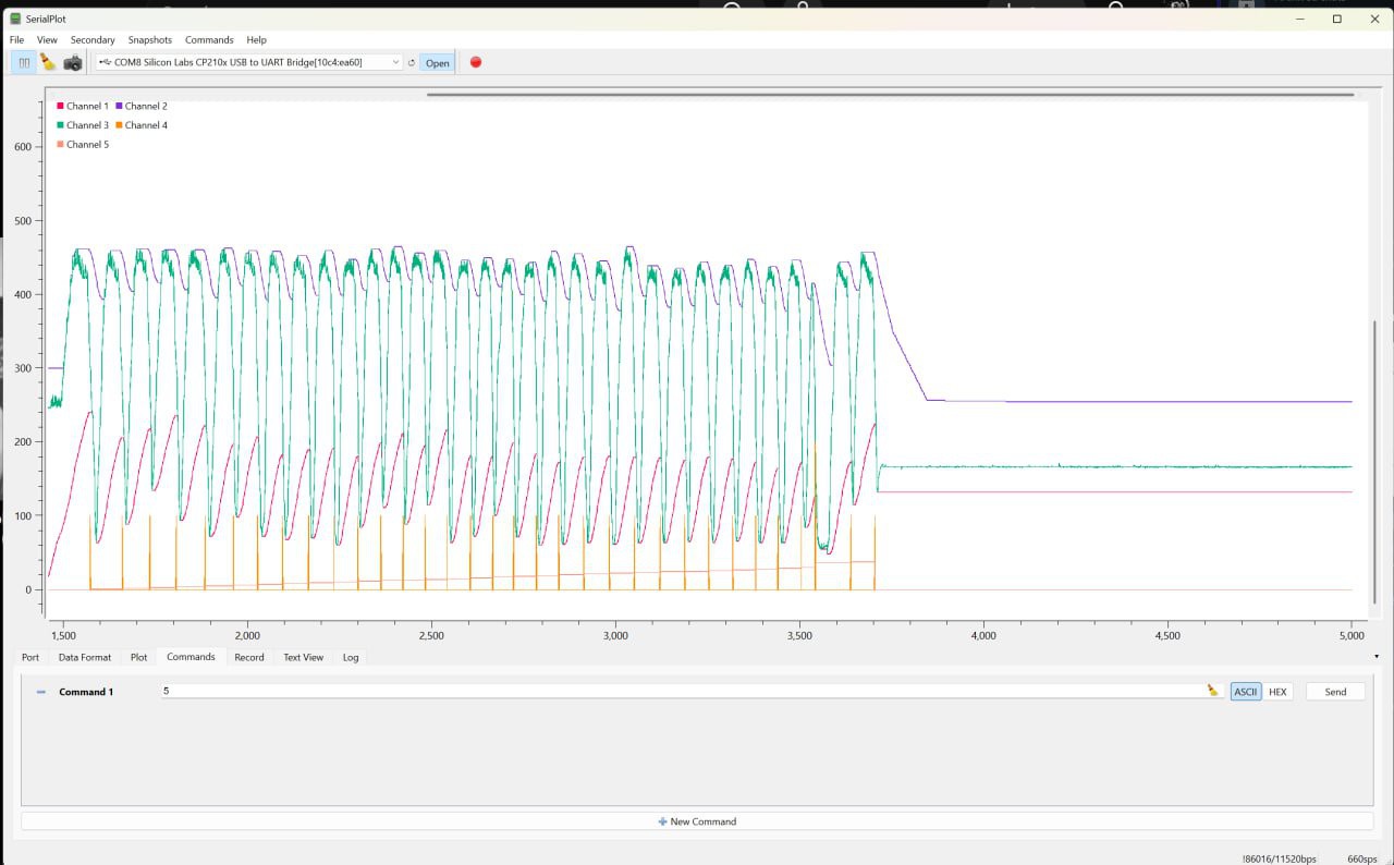
For comparison this is the regular code wheel without touch-ups (this graph is from a sensor with 200K collector resistor, so absolute values are different).
![]()
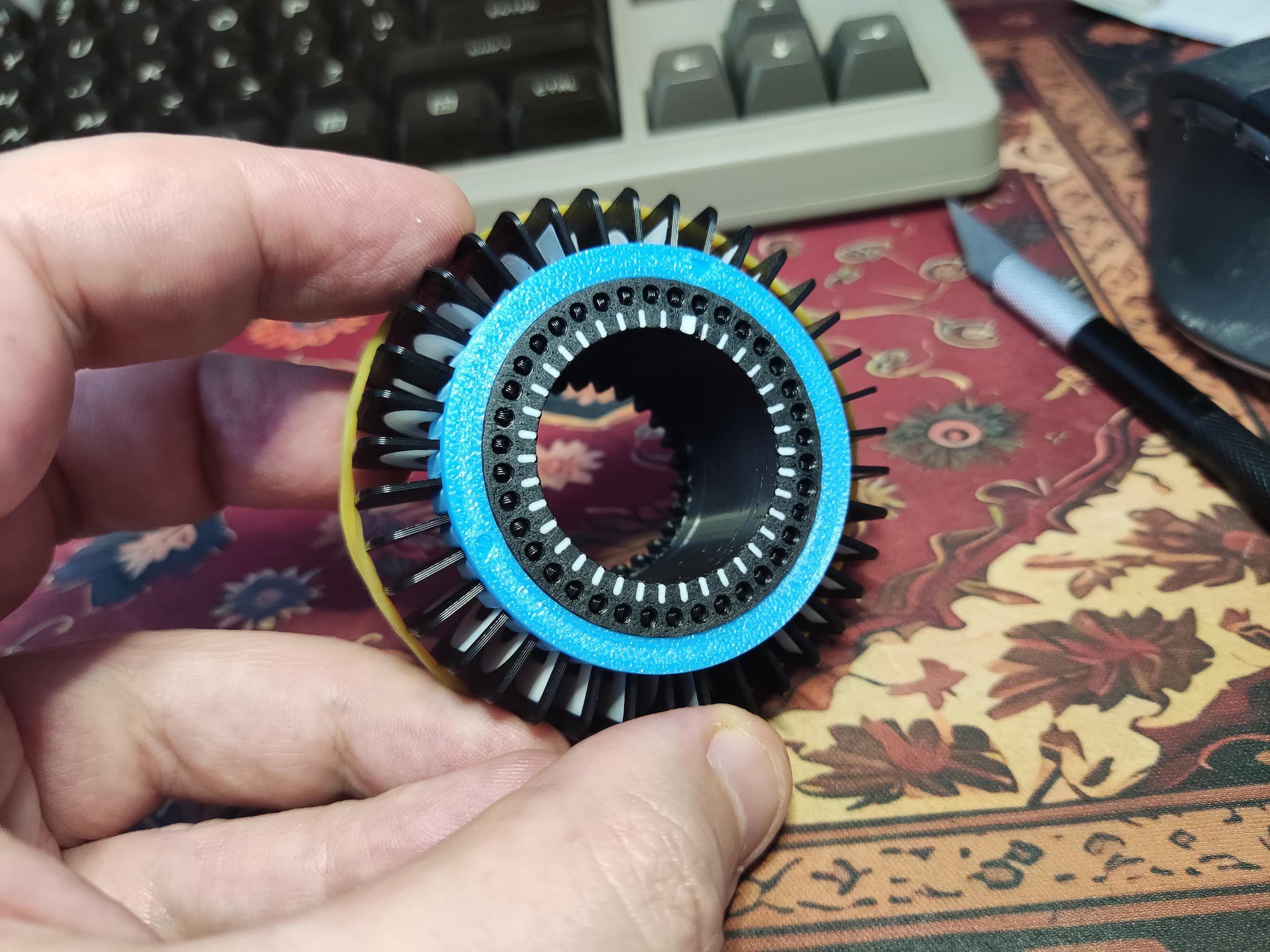
The tick marks on the code wheel. A thick one represents home position.
![]() Luckily my simple algorithm turned out to be robust enough to cope with irregularities. I decided to add another tunable parameter, the tracking divisor. It adjust min/max leakage rate. The larger the value, the slower the peaks decay towards the middle. It proved to be quite useful when tuning individual displays.
After just a few minor mishaps inevitable when connecting a bunch of wires I managed to tune up each display and get them all work together.
![]()
I think I2C was a good choice because it gives some flexibility and spending a bit of time to add tunable parameters definitely was worth it. It is surprising how much variance there is between individual displays. They all use same parameters and the motors are from the same bag.
A celebratory message from Father Jack:
I'm feeling almost confident enough to add 4 more characters. 10 split-flaps characters ought to be enough for everybody.
-
Boring bits
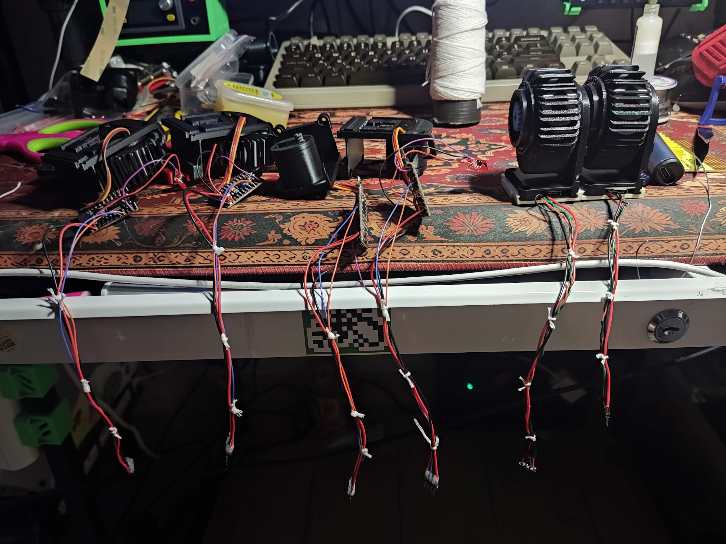
08/30/2026 at 00:07 • 0 commentsIf I were less lazy and made custom PCBs there would be so much less cable work. But I'm using store-bought breakout boards here so it's a lot of wire. I'm trying to measure the lengths and braid them. Takes a lot of time, but I think the results look ok.
![]()
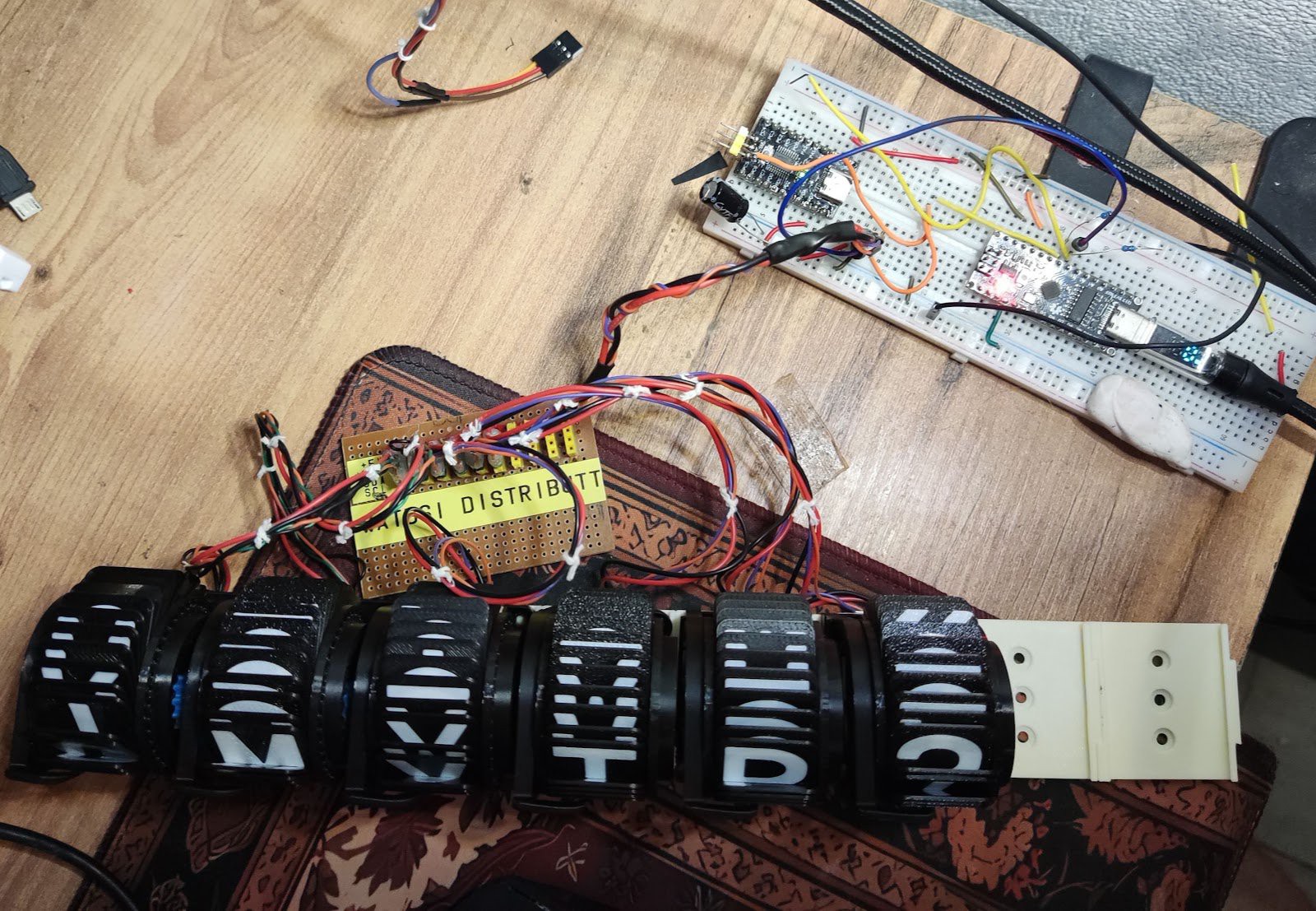
Put together 6 units, of which only 4 are moderately tested. The scale is pretty terrifying. Despite me calling them "mini" they are not as small as I thought they would be.
![]()
I still would like to have at least 8 characters before I call it quits, 10 would be amazing. And I literally have nowhere to put this huge thing once it's complete.
Two left-most characters are already tested and they mostly work.
Others, they will probably require some creative debugging.
-
I2C/power distribution board
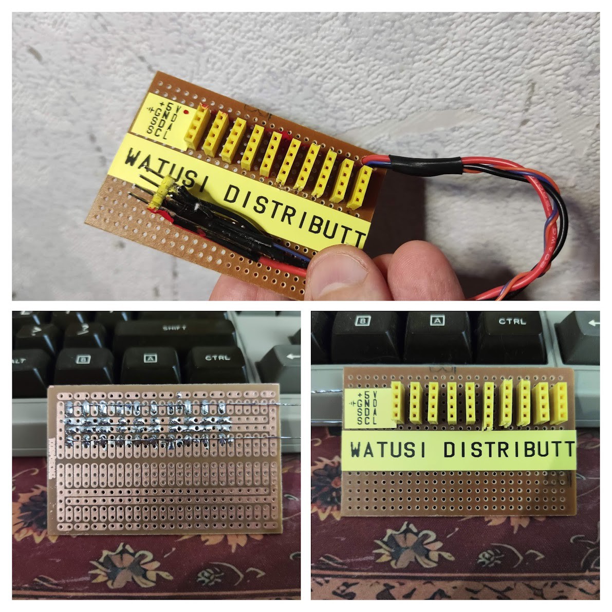
08/28/2026 at 10:27 • 0 commentsThis is probably the least exciting but necessary part of the project.
![]()
I had these very barebones by modern standards boards waiting to be used for something and finally that day has come. Just 4 strips: 5V, GND, SDA and SCL.
I was on the fence about using I2C vs implementing multiple UARTs on a Pi Pico. I2C won because I had a 5V Arduino Nano on my desk already and the letters are driven by 5V micros as well so it seemed like one potential headache less at the moment.
Why UARTs could be better? Look at this board:
![]()
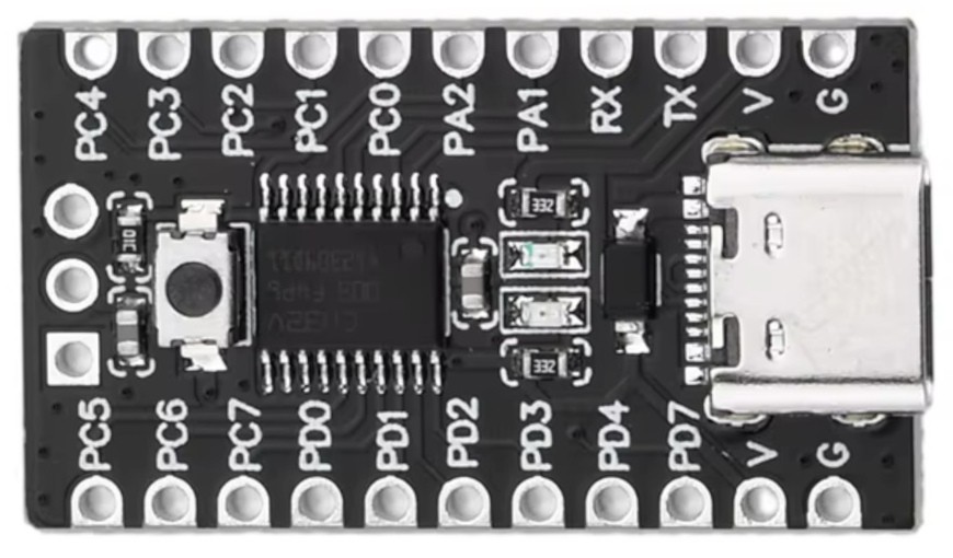
What you see on the right is a connector that's USB-C mechanically, but it is in fact connected to RX/TX pins on the MCU. It would be convenient to use one connector for everything, even though it's not standard. But you can't use star topology with conventional UART so I had to give it up.
I2C is mapped to PC1/SDA and PC2/SCL.
In fact I'm not sure if I2C can't be remapped to RX/TX pins. Something to check out as it could save a lot of soldering.It can't be remapped to PD5/PD6 pins used for TX/RX.
 I guess that's it. Definitely do not want to build more.
 Luckily my simple algorithm turned out to be robust enough to cope with irregularities. I decided to add another tunable parameter, the tracking divisor. It adjust min/max leakage rate. The larger the value, the slower the peaks decay towards the middle. It proved to be quite useful when tuning individual displays.