Xavi Paz
-
Building the RetroBox Modem prototype
9 hours ago • 0 commentsRetroBox Modem is still under active development, so these instructions describe the current working architecture rather than a finalized production design. Some components, mounting details and interfaces may change as the project evolves.
1. Prepare the main controller
RetroBox is built around a small Linux-capable single-board computer with WiFi connectivity.
The controller handles the Hayes command interpreter, network connections, OLED interface, status LEDs, modem audio and serial communication with the host computer.
For modern computers, the system can expose a USB serial interface directly.
2. Connect the OLED display
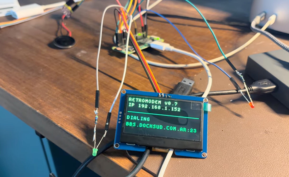
A small monochrome OLED display is connected to the controller and used to show useful modem information such as:
- IP address
- WiFi signal
- current modem state
- connection status
- dialing and online information
The display allows RetroBox to provide useful feedback independently of the computer connected to it.
3. Add the modem audio hardware
A digital audio output stage and small internal speaker reproduce the sounds associated with dialing and modem negotiation.
The firmware handles dialing tones, carrier sounds and handshake sequences for different modem personalities.
Audio is one of the areas still under active development, as the goal is to make the different connection profiles sound as authentic as possible rather than simply playing one generic modem recording.
4. Wire the front-panel indicators
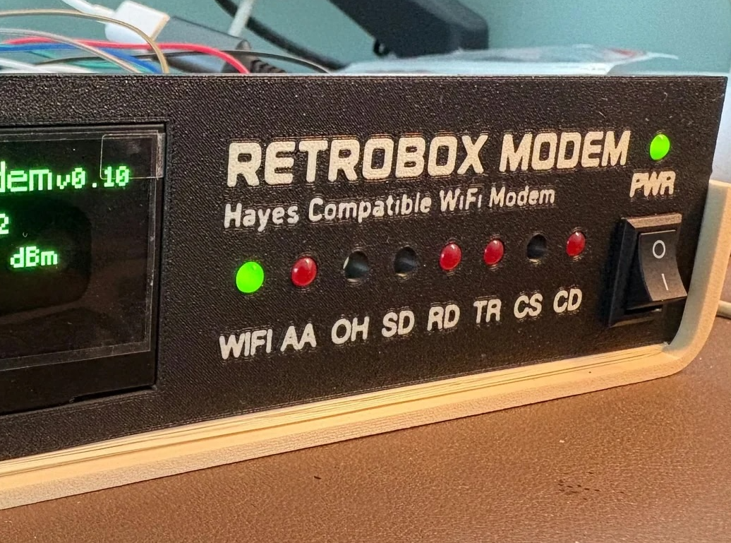
The front panel follows the style of traditional external modems and includes the following indicators:
WIFI AA OH SD RD TR CS CDA separate
PWRindicator shows that the modem is powered.The firmware controls the LEDs according to WiFi state, connection status, serial activity and modem operation.
5. Add modern and vintage serial connectivity
Modern computers can communicate with RetroBox through USB serial.
Vintage computers can use a traditional RS-232 connection through a serial level-conversion stage.
This allows an older machine to communicate with RetroBox in the same way it would communicate with a conventional external modem.
The basic architecture is:
Computer → Serial / USB → RetroBox → WiFi → TCP/Telnet → BBSThe computer only sees the modem interface. WiFi and network communication are handled internally by RetroBox.
6. Install the firmware
The RetroBox firmware implements the Hayes-compatible command layer, network handling, modem states, display interface, LEDs, sounds and configuration system.
Once the firmware is running, opening a serial terminal and typing:
ATshould return:
OKA BBS can then be dialed using:
ATDhostname:portRetroBox establishes the network connection internally and returns the appropriate modem result code to the host computer.
Other supported modem-style functions include escape sequences, returning online, persistent configuration, favorites and connection history.
7. Print and assemble the enclosure
RetroBox uses a custom 3D-printed enclosure designed to resemble the external modems and peripherals commonly found beside computers during the dial-up era.
The enclosure consists of a cream-colored body and a contrasting front panel with integrated lettering.
The design has gone through multiple physical revisions to refine:
- OLED positioning
- LED alignment
- switch fit
- PCB mounting
- connector placement
- internal clearances
- ventilation
- lettering and two-color printing
Because the hardware is still evolving, some internal mounting points and dimensions may change between prototype revisions.
8. Test the modem
Connect RetroBox to a terminal program and verify the Hayes command interface:
ATOKThen dial a BBS:
ATDhostname:portRetroBox handles the network connection internally and returns:
CONNECTFrom that point, the computer communicates with the remote BBS through the RetroBox Modem.
Different modem personalities and data-pacing settings can then be used to experiment with the experience of different dial-up speeds.
Prototype note
RetroBox Modem is still a work in progress.
The enclosure, firmware, serial interfaces, audio system and some hardware components are continuing to evolve. These instructions document the current working prototype and the general architecture of the project rather than a final production version.
-
Connecting modern & vintage hardware
9 hours ago • 0 commentsRetroBox is designed to work with both modern and vintage computers, but the physical connection is different depending on the machine.
Modern systems can use USB serial directly, which makes development and testing straightforward.
Older computers usually expect a real serial interface, so RetroBox also supports RS-232 through a MAX3232 level converter. That allows the modem to present proper serial voltage levels to vintage hardware without changing the way the computer expects to communicate.
The basic idea is deliberately simple:
Vintage computer → RS-232 → RetroBox → WiFi → BBSThe computer only sees a Hayes-style modem. It sends AT commands, dials a destination and receives familiar result codes such as
CONNECTandNO CARRIER. Everything involving WiFi, TCP and Telnet happens inside RetroBox.I have already tested working prototypes with 486 and Pentium-era PCs, and the same firmware can also be used from modern computers over USB.
One of the next areas I am continuing to refine is compatibility with more vintage platforms and serial adapters, while keeping the modem itself as universal as possible.
-
Recreating the dial-up experience
9 hours ago • 0 commentsGetting a computer connected to a BBS over WiFi is relatively easy.
Making that connection feel like a modem is much harder.
RetroBox is not intended to be just a transparent serial-to-WiFi bridge. A large part of the project is about recreating the little behaviors that made dial-up modems recognizable: dialing, handshakes, result codes, carrier states, LEDs, delays and sound.
The firmware currently includes several modem personalities, from V.22bis through V.90, together with a separate pacing system that controls how quickly data is delivered to the terminal.
This allows the same BBS to be experienced at very different speeds. One of my favorite tests is connecting to the same system first at 300 bps pacing and then again at 56K. The difference is dramatic, even when the destination is exactly the same.
Audio has turned out to be one of the hardest parts of the project. Different modem standards did not all sound the same, and simply playing a generic “dial-up sound” is not enough if the goal is to make the experience believable.
I am still refining the handshake and carrier audio and experimenting with how closely the sound should follow the selected modem personality and data speed.
The front-panel LEDs are also part of that experience. WIFI, AA, OH, SD, RD, TR, CS and CD provide visible feedback while the OLED shows the current state, network information and connection details.
This part of RetroBox is still evolving, but it is probably the part I enjoy working on the most.
![]()
-
Designing and 3D printing the enclosure
9 hours ago • 0 commentsThe enclosure has taken almost as much iteration as the electronics.
I wanted RetroBox to look like a piece of hardware that could plausibly have sat next to a computer in the 1980s or 1990s, rather than simply putting the electronics inside a generic project box.
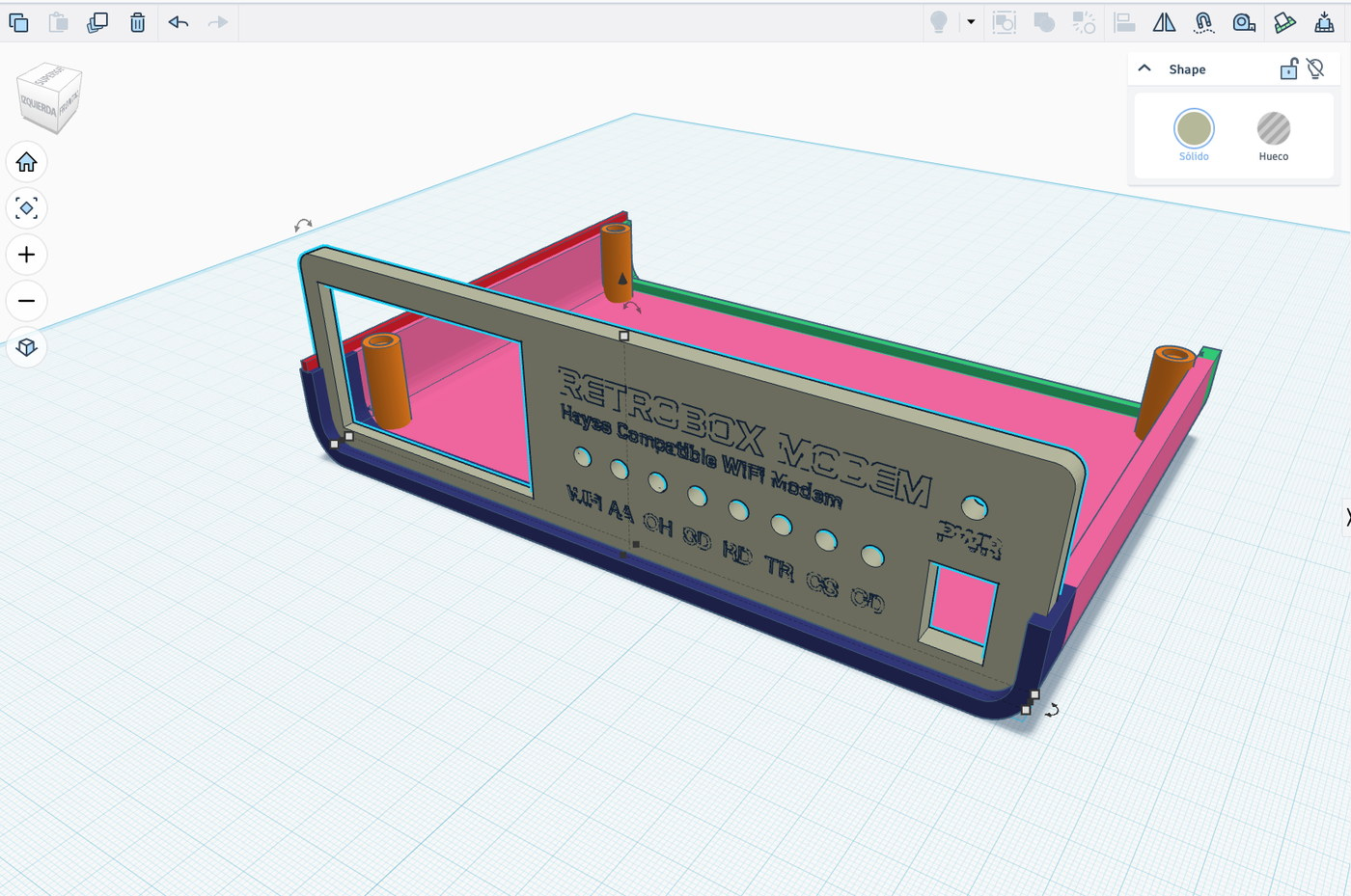
The case is 3D printed and has gone through many revisions while I adjusted the OLED position, LED alignment, front-panel lettering, PCB mounts, switch fit, internal clearances and ventilation.
Small changes turned out to matter a lot. LED holes were adjusted repeatedly to get the right fit and depth, the PCB mounting posts were refined so the LEDs sit correctly against the front panel, and the OLED opening and position were changed several times before everything lined up properly.
The front panel is printed in two colors, with a black face and cream lettering, while the enclosure uses a warm beige/cream inspired by vintage computer hardware.
Most of the recent prototypes have been printed on a Bambu Lab A1 using a 0.4 mm nozzle and a 0.16 mm layer height. The lettering is printed as an inlay rather than painted afterward.
One of the advantages of 3D printing this enclosure is that the mechanical design can evolve together with the electronics. When a connector, PCB position or internal component changes, I can modify the case and test another physical revision immediately.
At this point the enclosure is very close to the shape I originally had in mind, although I am still refining small tolerances and internal mounting details.
![]()
-
From idea to working prototype
9 hours ago • 0 commentsRetroBox Modem started as an experiment: could a modern single-board computer behave enough like a traditional Hayes modem that both old and new computers could use it naturally?
The first goal was simple: open a serial terminal, type
AT, receiveOK, and then useATDto connect to a real BBS.Once that worked, the project quickly grew. I added WiFi networking, TCP/Telnet handling, an OLED display, status LEDs, modem result codes, favorites, persistent configuration and audio.
The first successful BBS connection was the point where RetroBox stopped feeling like a software experiment and started feeling like a modem.
There is still a lot to refine, but the core idea is now working: a computer talks Hayes, RetroBox handles the modern network underneath, and the user gets something that feels much closer to the dial-up experience.
![]()
RetroBox Modem
A Hayes-compatible WiFi modem for vintage and modern computers, with real BBS connections, AT commands and classic modem sounds.