-
Final Circuit
06/13/2017 at 00:24 • 0 commentsI finally got the chance to redraw the circuit using KiCad.
I got some seed money from SupplyFrame (thanks!) and that means I am obliged to make the design open. ;)
This is the final circuit for the project:
http://www.afdhalatifftan.com/2017/06/low-cost-active-battery-balancer.html
I had to relinquish my intention of selling it because of I am financially challenged at the moment.
Feel free to use the design, improve it and share it! :)
-
100% Balancing Accuracy?
05/07/2017 at 23:56 • 0 commentsI finally made an improved version of the board. Main changes are:
-better pcb layout-the use of 0.05% resistor
-reverse polarity protection (schottky diode)
-overcurrent protection (polyfuse)
I plan to include overvoltage protection (zener diode) in the future.
To my surprise, my 6000 counts multimeter (count at each 1mV) reports accuracy of 100%! :)
I know it is not true, maybe near 99.9%, but, that is the best resolution that I can get for now.
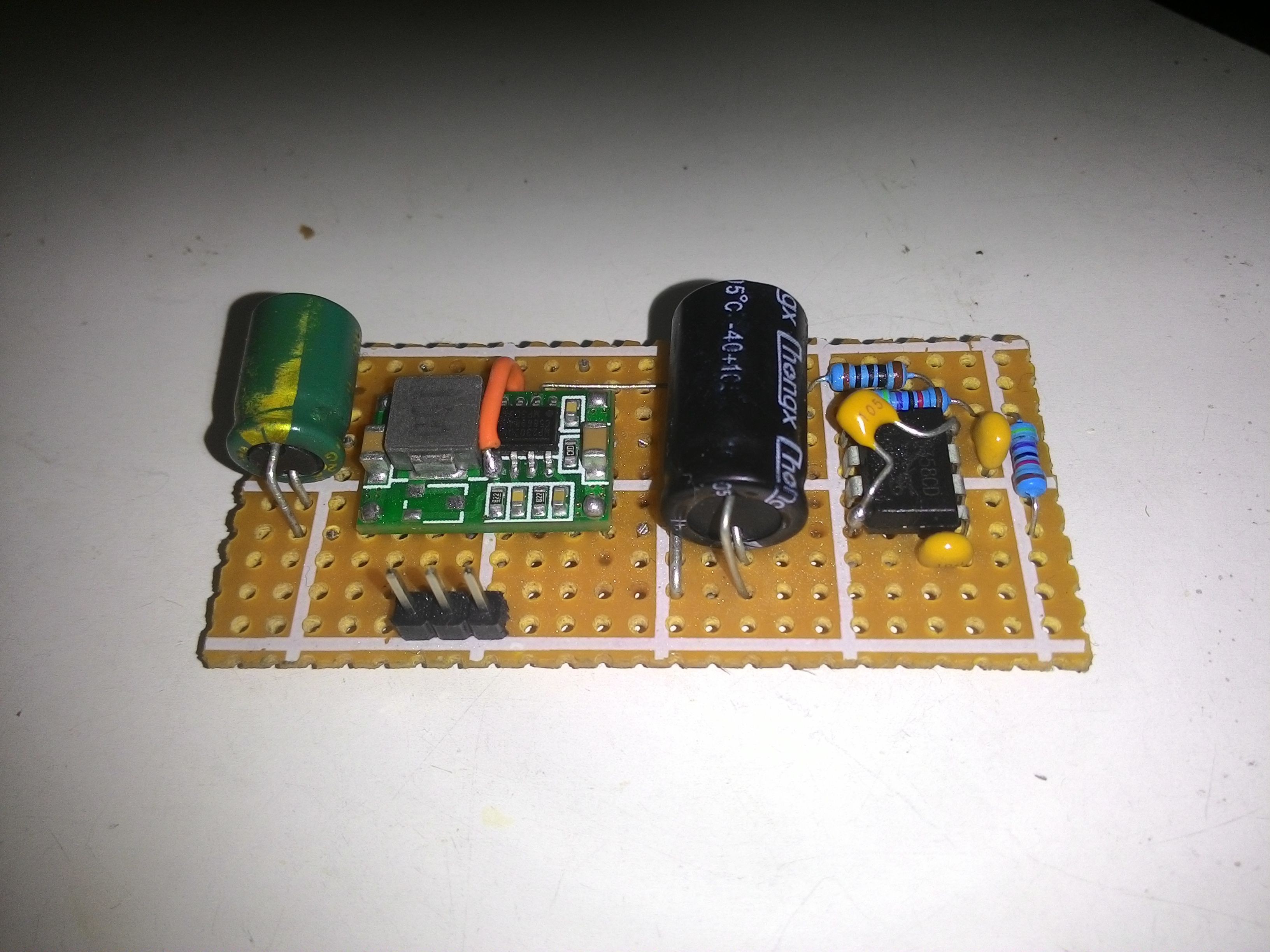
Front view:
![]()
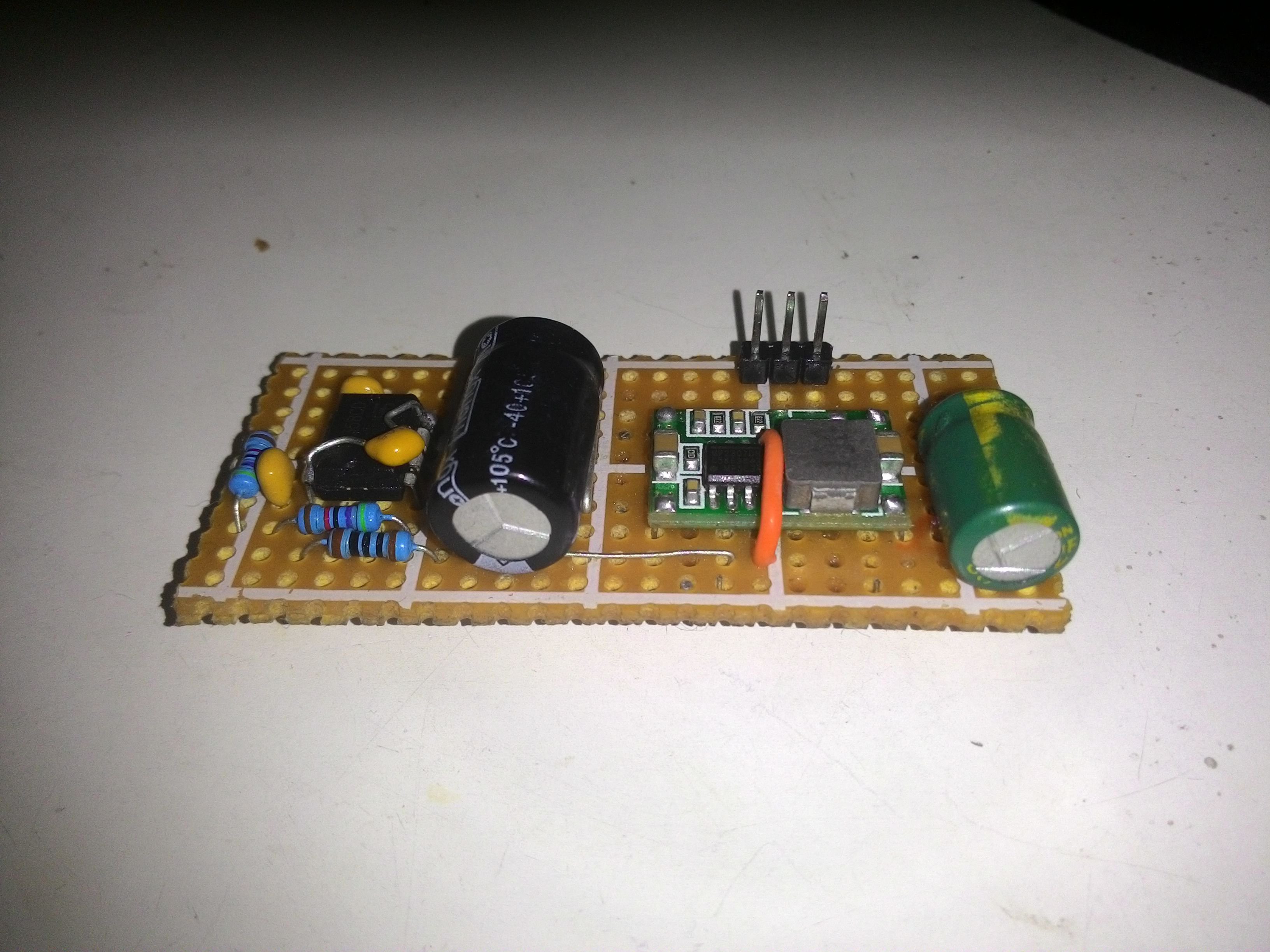
Another view:
![]()
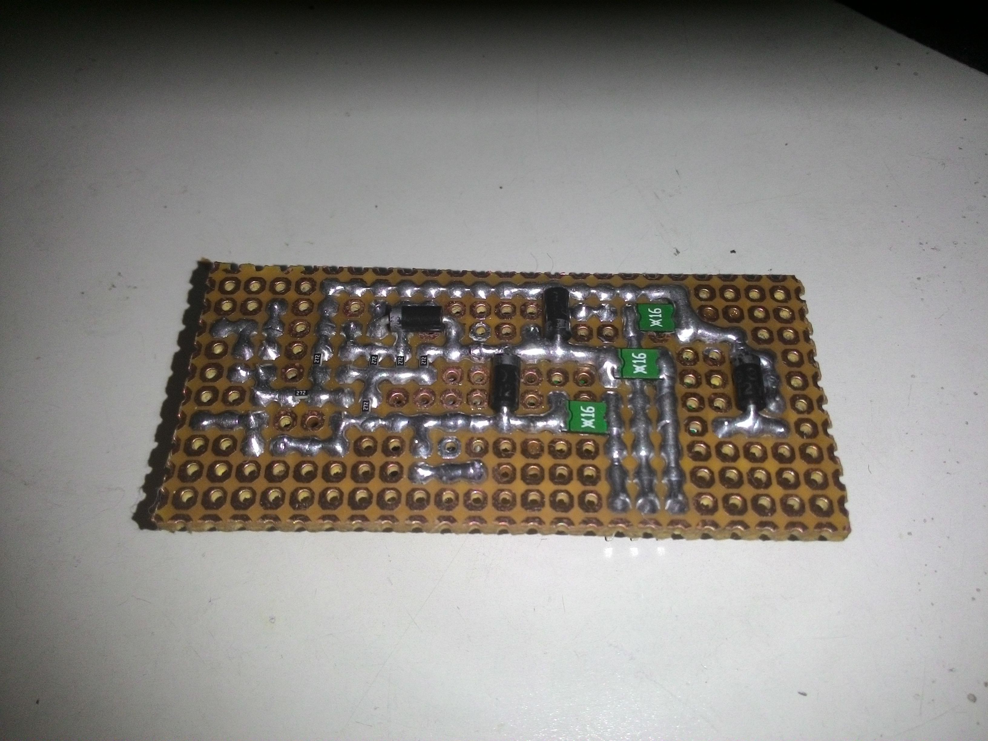
Bottom view:
![]()
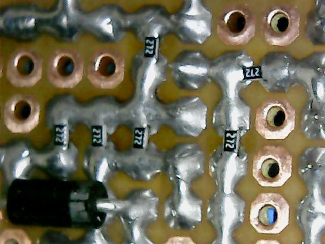
Close-up of the smd 0.05% 2.7kR 0603 resistor on the 0.1" pitch perfboard:
![]()
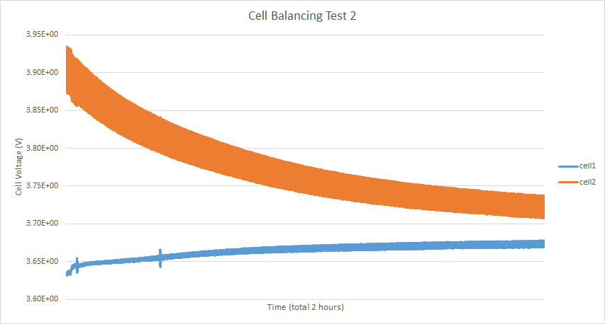
Not only the accuracy improved, the balancing time also has improved:
![]()
As shown in the plot, both of the cells approaches center-voltage a lot faster than the previous board. Notice that the charge in the orange cell gets transferred into the blue cell.
The charge time is dictated by the resistance of the balancing lead. I found that it takes longer for it to balance if the difference is smaller 100mV, i.e. getting 1 amp at 100mV needs 100 milliohms cable.
It is difficult for me to achieve that low resistance because of the high wire gauge that I have used as the balancing leads.
At the moment, I am waiting for reviews from endless-sphere forum. After I got enough positive reviews, I will proceed to send the pcb to be manufactured.
-
Better Accuracy and Stability
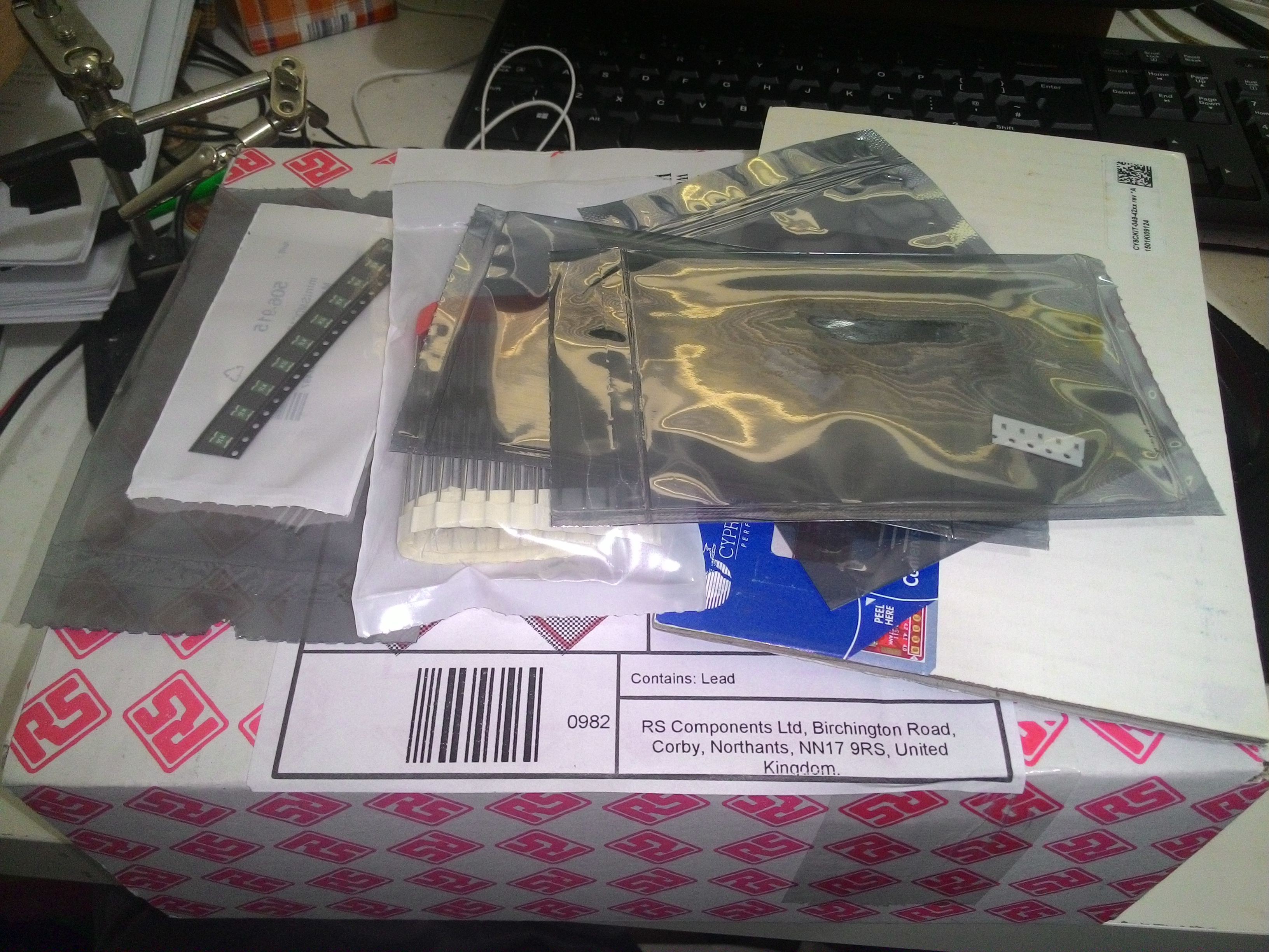
04/23/2017 at 02:35 • 0 commentsAs mentioned in my previous post, the accuracy was not that great, and because of that, I decided to try resistors with better tolerance. My RS order has arrived:
![]()
One of the components in the box was some 0.05% resistors.
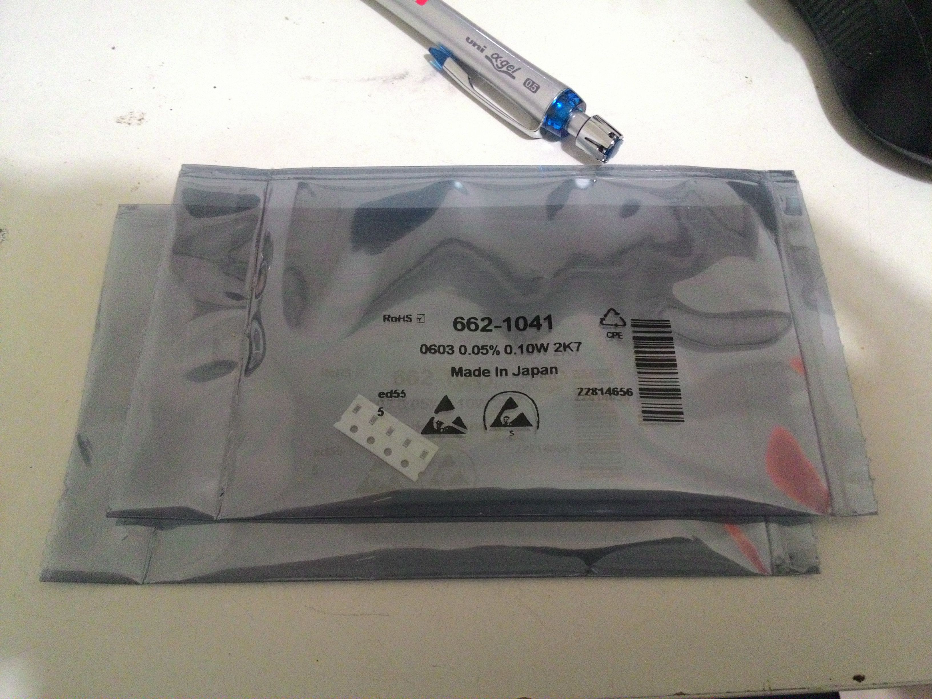
I measured it using my 6000 count multimeter and I have to say, all of them are spot on to the same value, I am impressed! I used to 5% resistor all my life and seeing the consistent readings make me excited. B-)
I know it is expensive, don't worry, I do plan to test the cheaper 0.1% resistors later.
![]()
Fitting the smd 0603 on the donut board can be tricky, so I just soldered some wires to make it easier to prototype.
![]()
Unfortunately, I accidentally break two of them :(
![]()
I also added an RC snubber to reduce the high frequency ringing on the half-bridge with the hope that it will reduce some of the EMI emissions.
I also had to clean all of the flux residues on the board because I found that it is slightly electrically conductive.
The result? The balancing voltage is now within 0.3% (that is less than 10mv for 4.2V lipo cell).
I believe the error is coming from the non-ideal properties of the opamp (such as input voltage/current offsets, etc).
At first, I was skeptical if the opamp can handle the accuracy that I needed, now, I am glad because the cheap LM358 is still usable for this low tolerance project.
I hope to find an equally cheap better opamp than LM358, but, I failed to find one yet. Any tips guys?
I think I am getting closer to the end now. The next step would be to make a pcb for it.
-
Filtered Power Supply for Opamp
04/14/2017 at 21:28 • 0 commentsImage below shows ac-coupled supply rail (top yellow) and the half-bridge output (bottom blue).
As can be seen, the rail fluctuation is non-negligible and it will affect the opamp performance if left untreated.
The bridge output is stable at near 50% duty cycle, this indicates a good feedback loop.
![]()
To improve the opamp's ripple rejection, I added a diode and a capacitor at the opamp's Vcc pin to isolate the noisy power rail from the opamp. I also added flyback diodes to suppress any possible ringing bemf.
I also added a direct current path (green wire) from the output to the battery balancing node. This allows faster balancing.
![]()
The result was a cleaner opamp supply rail with minimised ripple:
![]()
And also, a better negative-feedback signal:
![]()
I am still struggling to remove the high-frequency component in the signal. Although the loop seems to be stable, I wanted to reduce it as much as possible to avoid EMI emissions.
I also tested the accuracy of balanced cells and it was measured to be around 4%, which is quite bad because of the sensitive nature of lithium battery chemistry.
-
Schematic For The Balancer
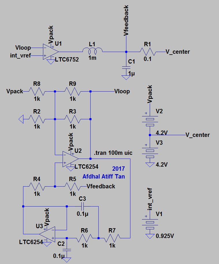
04/07/2017 at 22:18 • 1 commentYG asked for the schematic diagram of the balancer, so, I thought I post it here:
![]()
The circuit is the non-optimised version of the project. As you can see, the design is fully analogue with no expensive specialised chip.
I will update it to the optimised version at the end of the project.
The circuit should allow any buck converter chip to be controlled via a voltage reference (instead of a voltage divider network).
Feel free to tinker and contribute!
-
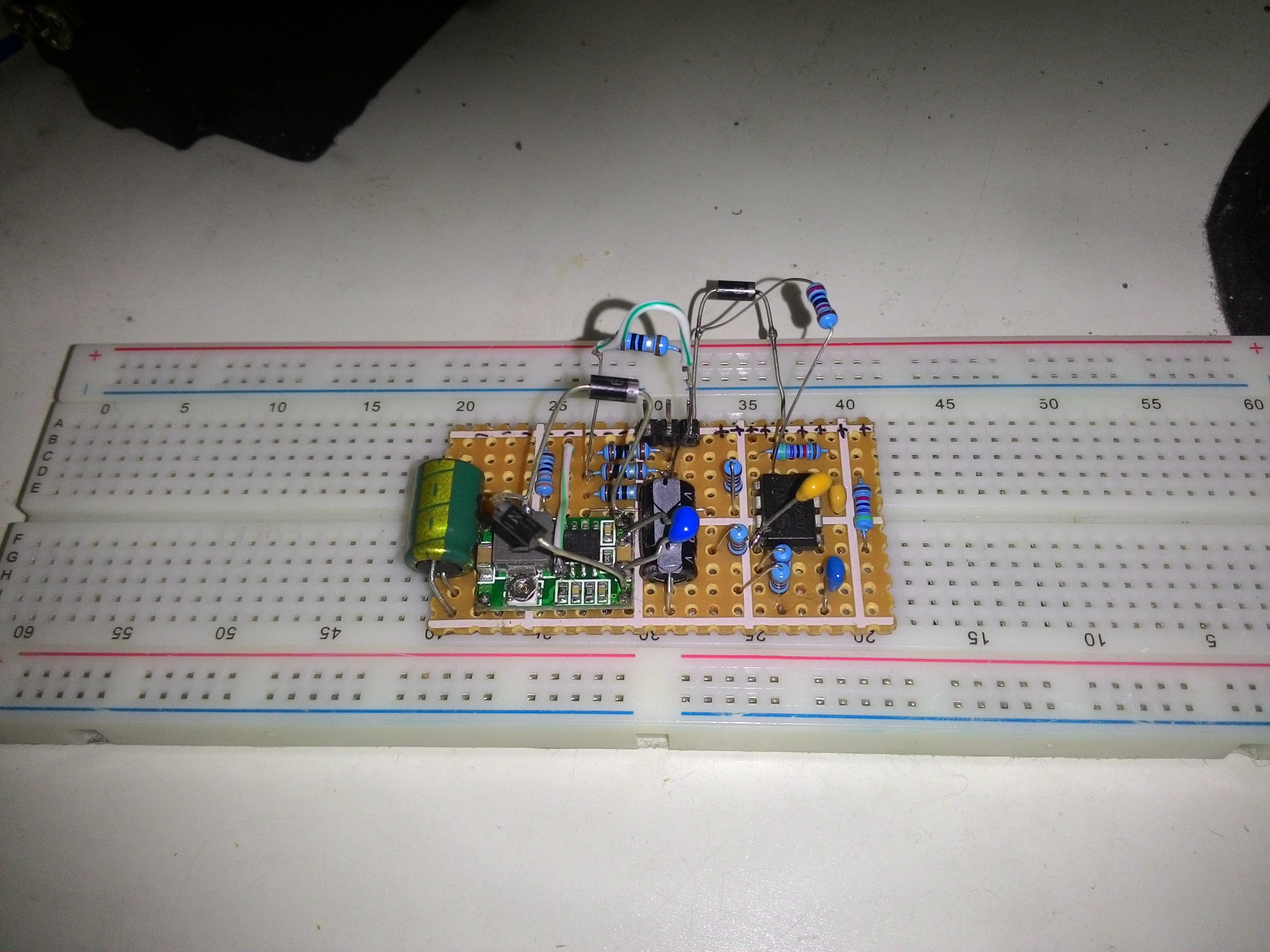
Improving Signal Probing
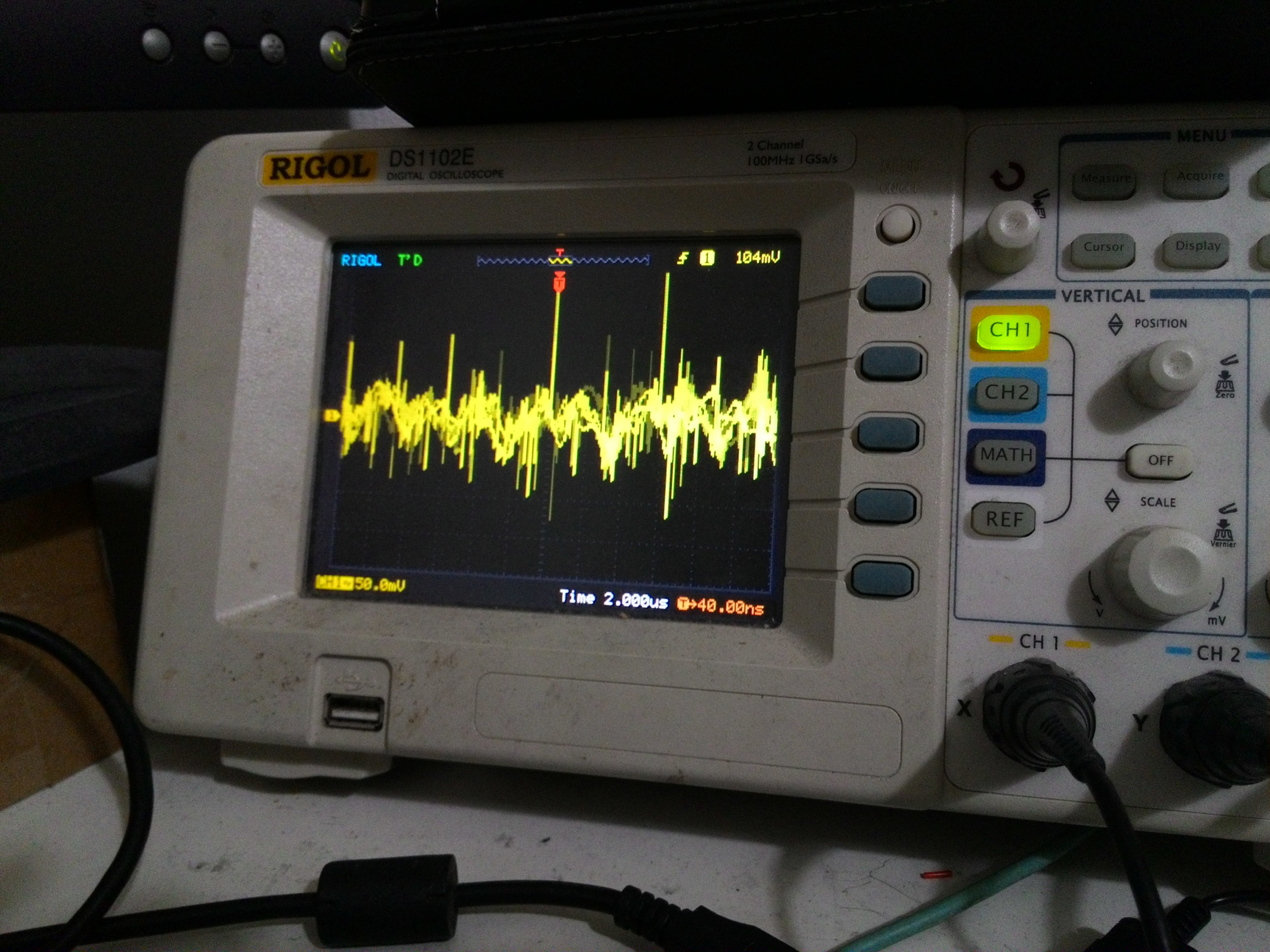
04/07/2017 at 22:09 • 0 commentsKC Lee gave me a link showing a technique to improve grounding on scope probes. Thank you!
I immediately try it and found that it does reduce stray coupling from the board.
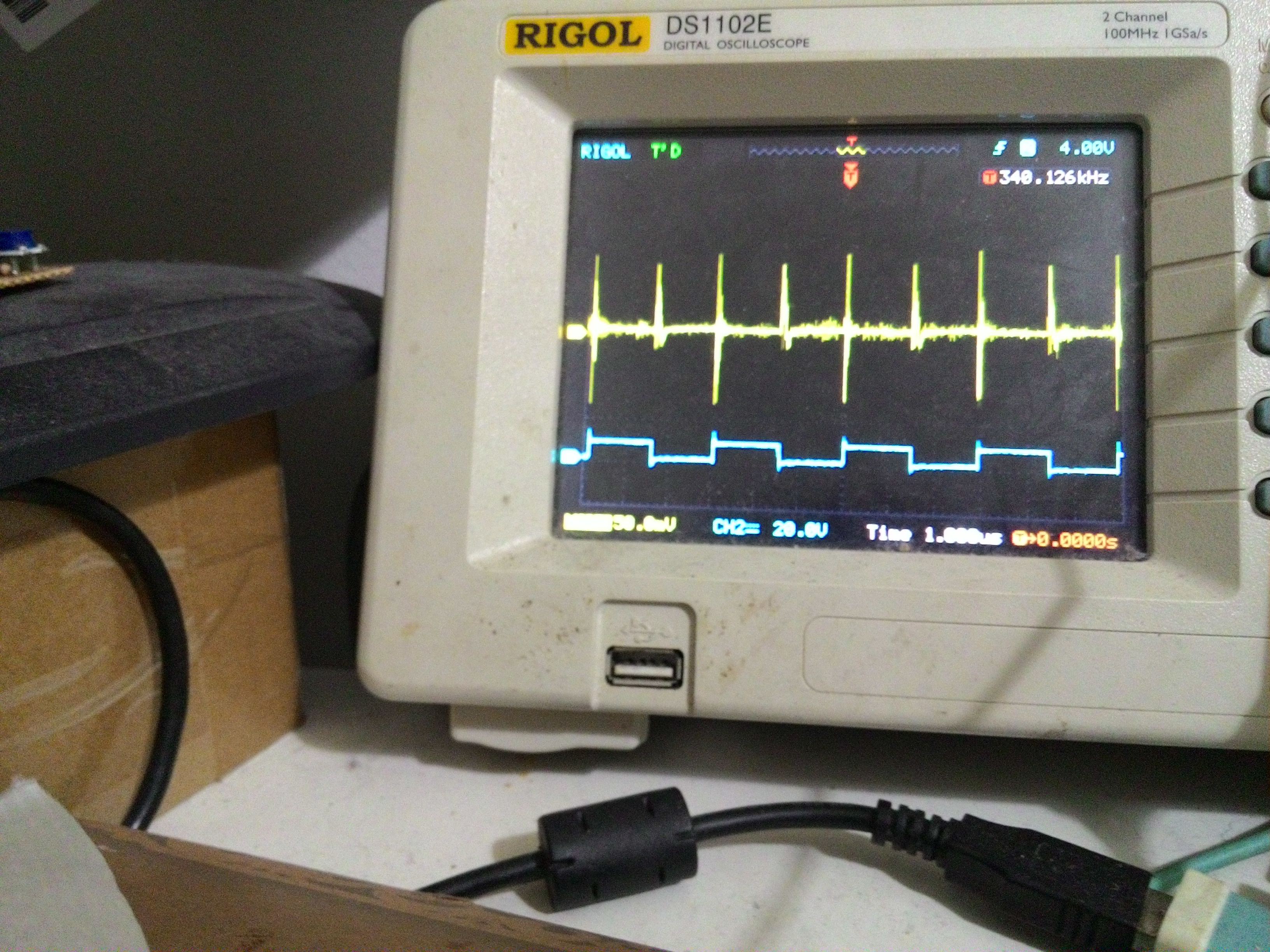
![]()
Unfortunately, the noise is still persists.
![]()
I later found that it is actually the high impedance balance leads that cause significant voltage drop every time the bridge transitions.
Next plans:
*Partition analogue and digital grounds
*Provide some power decoupling for the opamp
*Stiffen the supply rails for the synchronous buck converter chip
*Add flyback diodes to catch fast bemf
*Maybe replace the balance leads with lower gauge
-
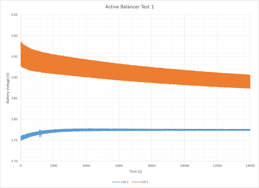
Active Balancer Test 1
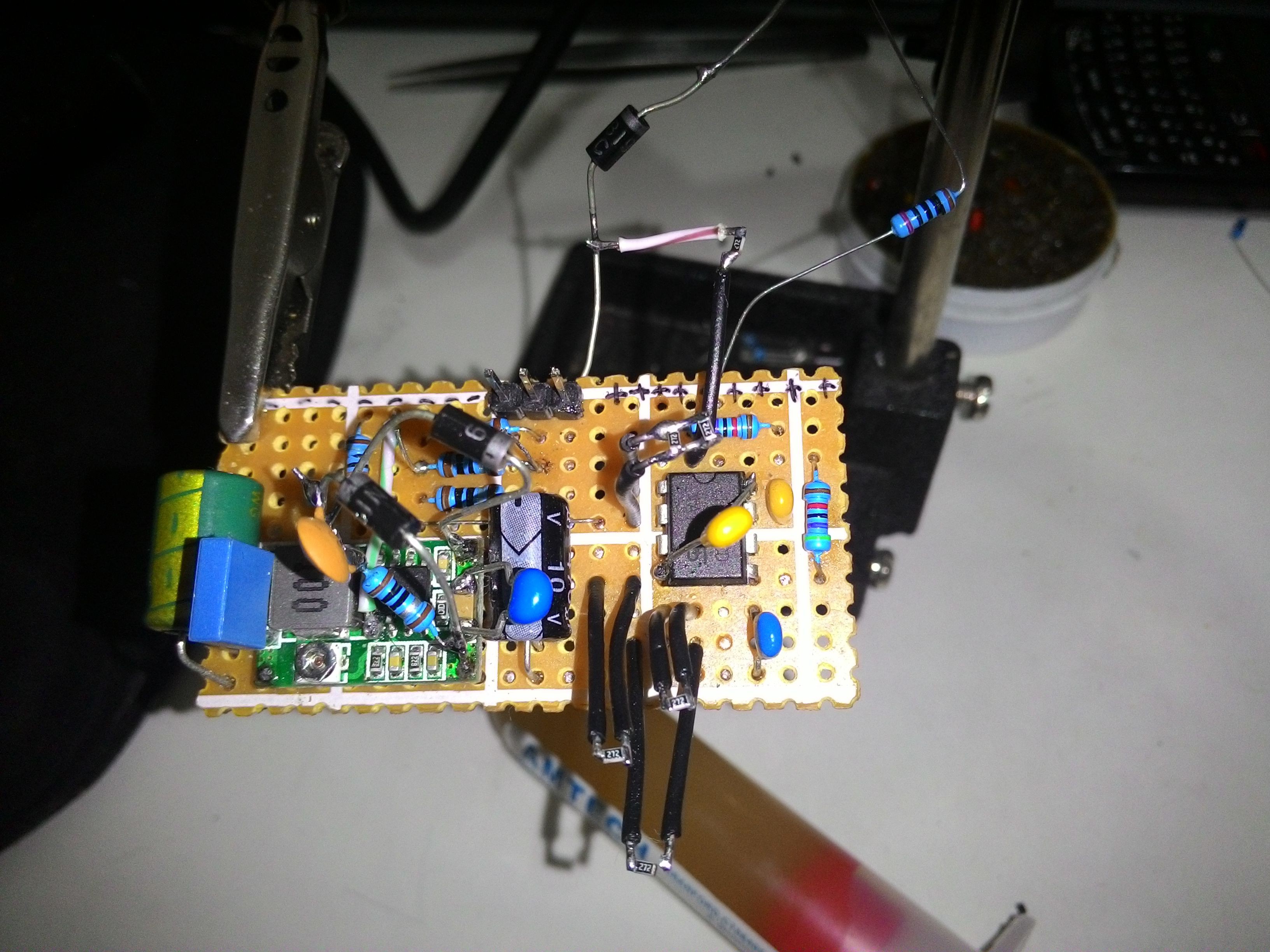
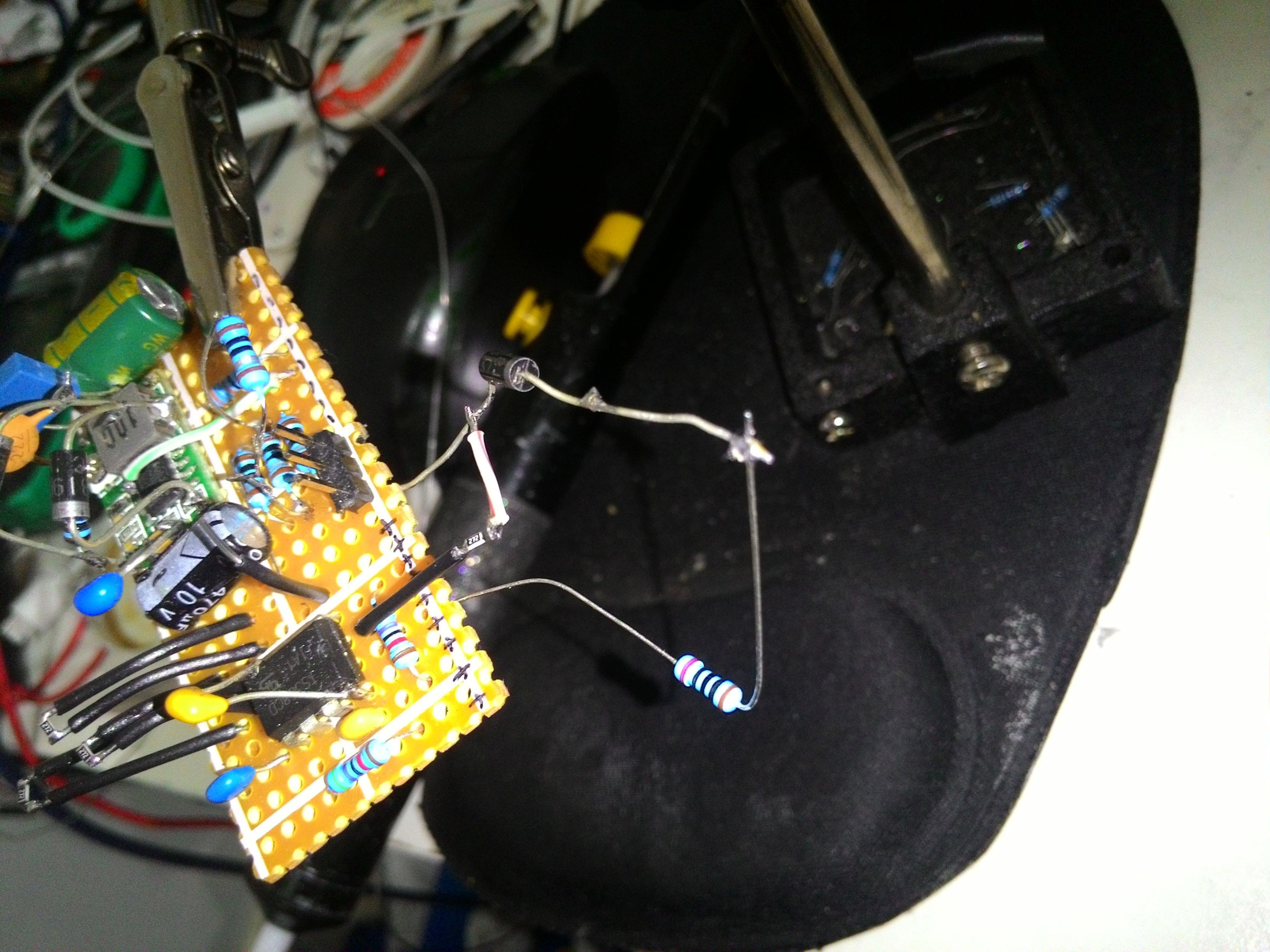
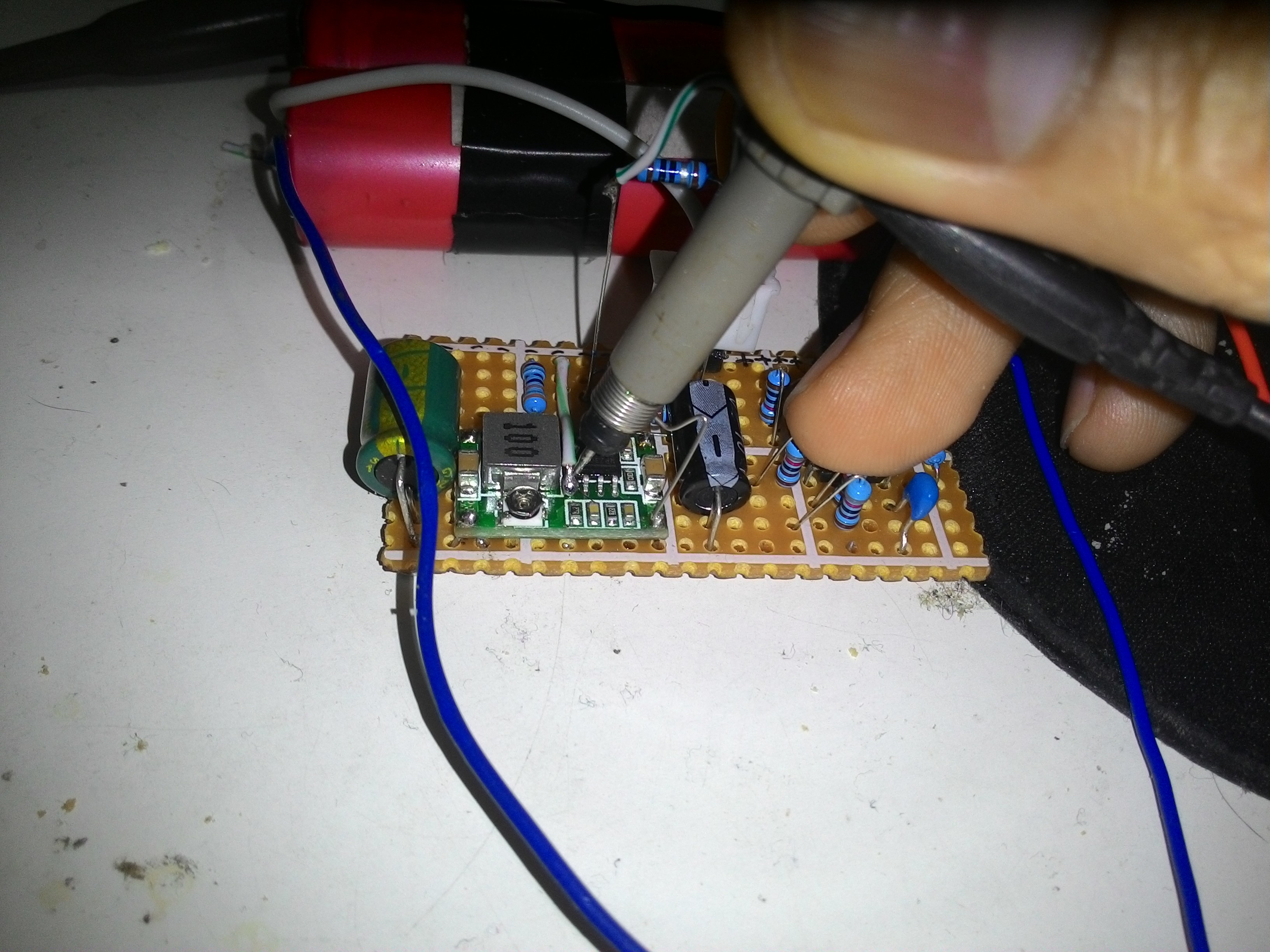
04/05/2017 at 20:02 • 0 commentsThis is the progress for today:
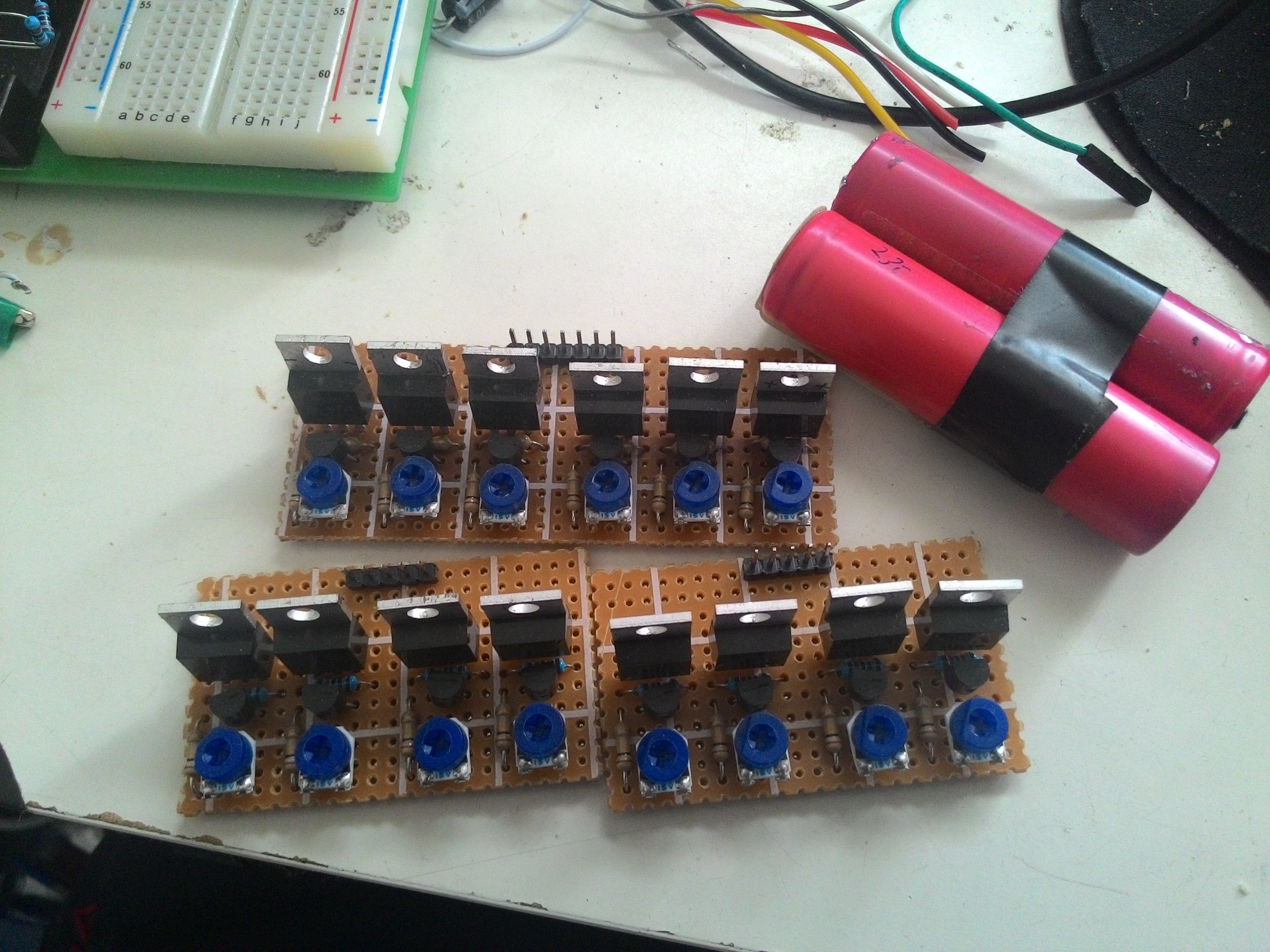
I finally transferred the dead-bug build on a more permanent perfboard:
![]()
To test it, I make a quick-and-dirty 2S 18650 pack:
![]()
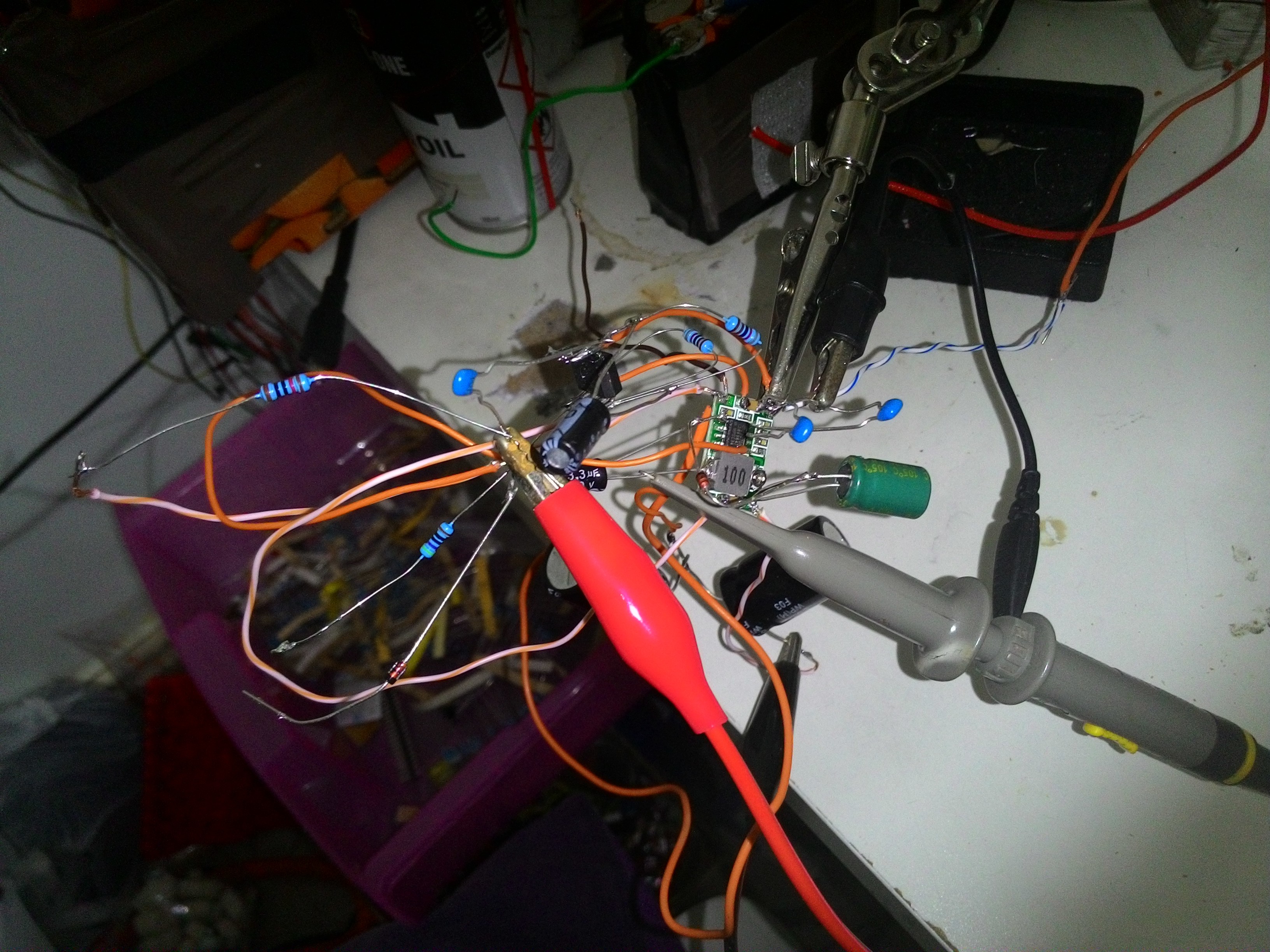
I need a datalogger, but, I don't feel like building one, so, I used NI myDAQ to log the voltage curve. Big shoutout to Ashley Roach for sponsoring the myDAQ! :) This is my test setup:
![]()
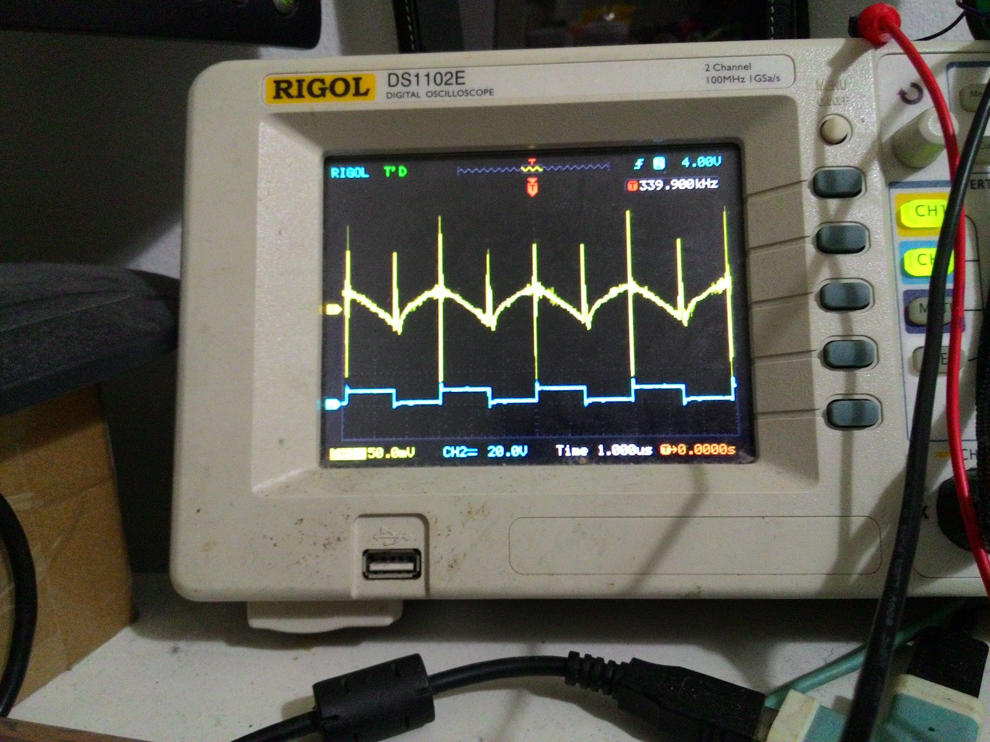
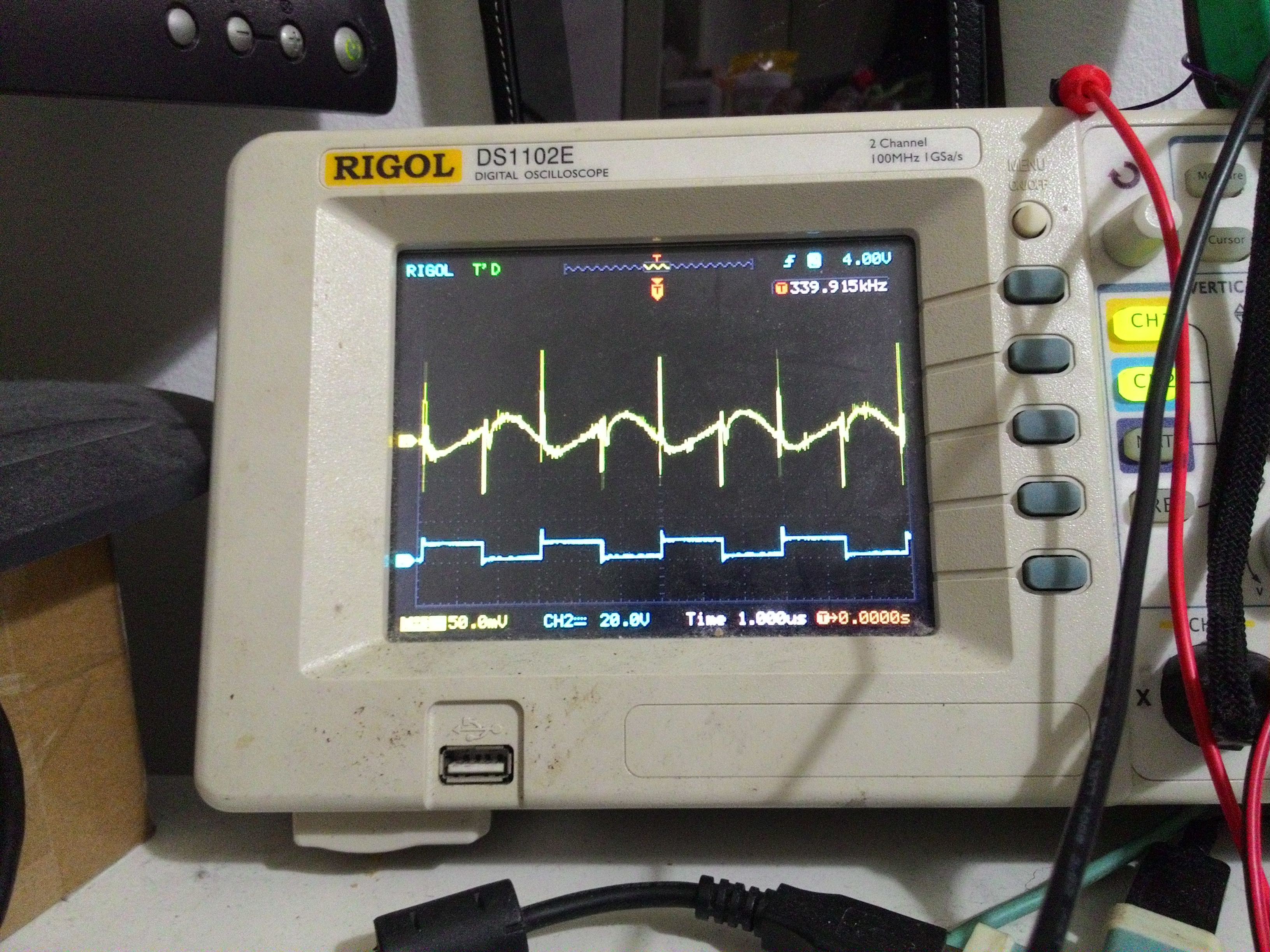
The yellow and the blue traces are opamp's output and half-bridge's output respectively.
Good news: it is running in closed-loop. Bad news: the switching bridge is noisy. :(
The 50% duty cycles indicates that it will make both of the cells to hold the same voltage, i.e. 50% for cell 1, 50% for cell 2.
![]()
Result so far:
-Good: Cell 1 and Cell 2 both is approaching the middle voltage.
-Bad: It takes too long.
Note: Cell 2 has more 340kHz ripples because it has more internal impedance.
![]()
Next plan are:
-Reduce the switching noise
-Make it balance the voltage faster!
-
Using Synchronous Buck Converter Chip to Transfer Energy
04/02/2017 at 23:31 • 0 commentsThis is the progress for today. Some modifications are added to the MP2307 board to convert the buck converter into a voltage follower. This means that the output voltage now can be set using a voltage reference instead of a resistive divider.
i.e. before modification, the voltage is set by 0.925v*(1+R2/R1), after modification, the output voltage is equal to voltage reference.
![]()
I will upload the schematic soon after I have fully optimise it.
-
My old dissipative balancer
04/01/2017 at 18:26 • 0 commentsI use my ebike daily to get to work. I need it to be as reliable as possible. Before starting this project, I use a simple balancer to top-balance my 14S pack on my ebike.
![]()
I prefer top-balancing instead of bottom-balancing because I am using recycled cells, none of them are matched in term of capacity. This means it is difficult for me to ensure full charge on all cells.
Other than the stored charge, the internal impedance of the entire pack is a lot higher for bottom-balancing because all of them are discharged at the same time. Although it is safer, that will make the other healthy cells unused.
The balancer worked ok, but, the shunt transistors get untouchable hot at each end of the charge cycle.
Because of this, I decided to find an alternative that does not generate dangerous wasted heat.
After few hours of research on google, I found a scheme called "active-balancing". Unfortunately, all of the solutions that I came across are expensive and the parts are difficult to source.
I am tempted to make an Arduino based controller for it, but, the mosfet and its driver gets expensive quite quick if I wanted to scale it up.
Low-Cost Non-Dissipative Active Battery Balancer
This cell balancer will transfer electrical charges from a strong cell to a weak cell. Ideal for electric vehicles.