Continuing from the requirements stated in the description, here is a more in depth look at those requirements and how the Spartan Mini meets them:
1. A board that could be hand soldered fairly easily.
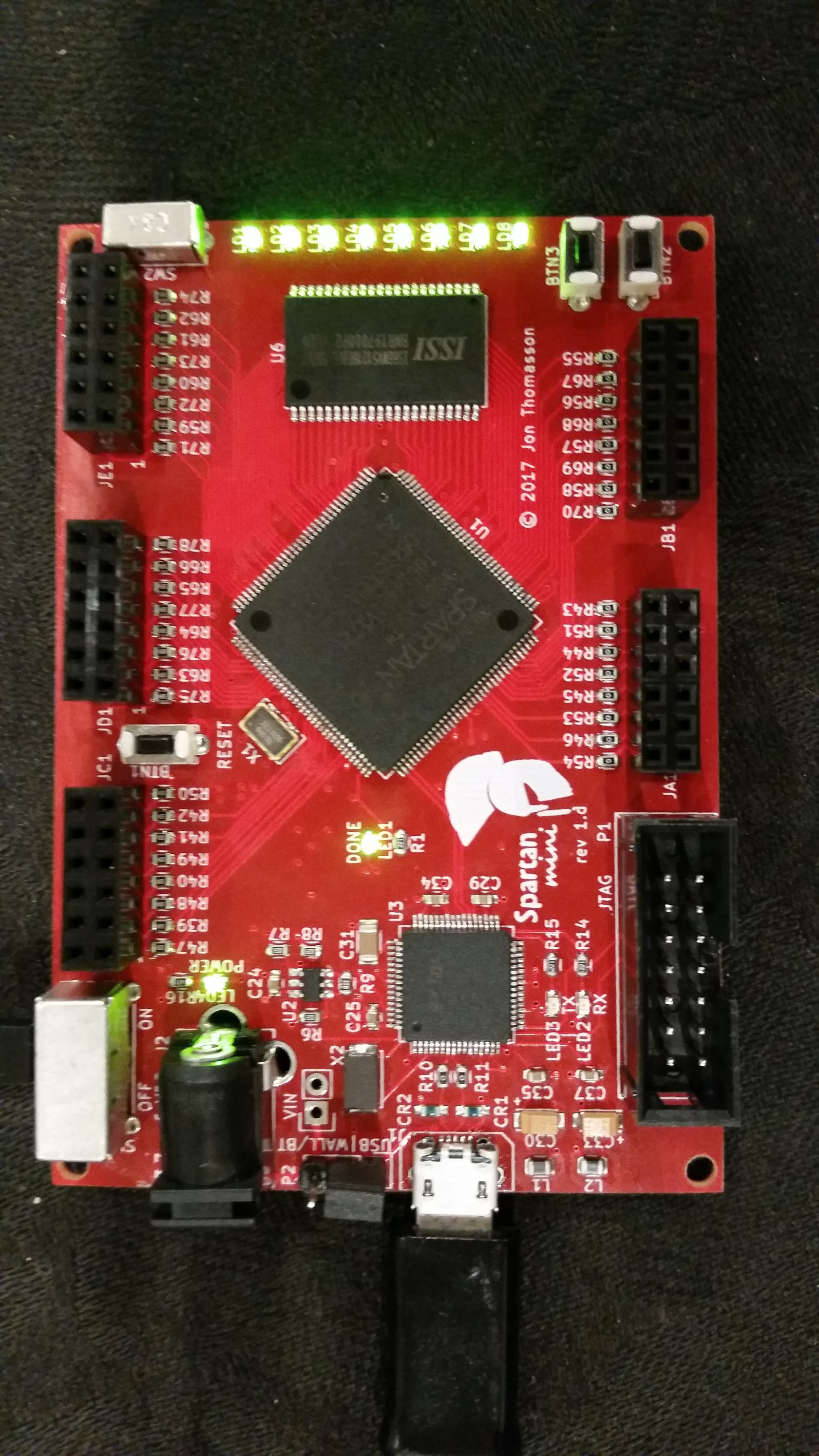
It seems like 90% or more of the FPGA's out there are in a BGA package. This made things difficult when considering this spec. I finally settled on the Spartan 6 FPGA because it came in a 144 pin TQFP package. The Spartan 6 is a well known and well supported FPGA among hackers and makers, making it a perfect candidate for the job.
2. A board that could be programmed easily with either JTAG or USB.
For the USB portion of this requirement, I decide to use the FT2232H chip by FTDI. This chip gave me both a USB to JTAG channel, as well as a USB to UART bridge that I could use later on to facilitate transferring data to the FPGA over the USB connection. I also wanted to include a full size 14 pin JTAG connector on board, to facilitate the use of a Xilinx Platform Cable USB programmer. This took a little more board space, but provides an easier interface to connect to the Xilinx programmer.
3. A board that could be powered with a wall wart and barrel jack.
This requirement was fairly simple to implement. The voltage requirements for the board fall between 3.7-6 volts dc. In addition to the barrel jack, the board provides jumpers to optionally be powered over USB, or a JST-PH connector and 3.7 volt lithium battery, as well as a voltage input pin.
4. The power needed to have a hard on/off switch.
Again, this requirement was not hard to implement. I just needed to select an adequate switch, capable of handling the current demands of the board.
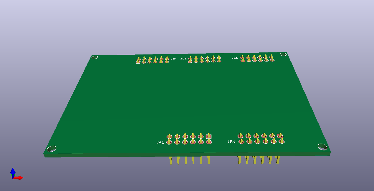
5. No IO pin of the FPGA should be wasted. All pins should be brought out to standardized connectors on the edges of the board.
Many FPGA boards today seem like they waste a lot of IO on providing connectors on board that likely aren't needed by every project such as SD cards, VGA, HDMI, etc. Instead of using up the IO on peripherals that may be unneeded I opted to instead route all GPIO lines out to PMOD connectors. These connectors seem to be picking up in popularity and there are already tons of sensors/peripherals to choose from in the marketplace that can be plugged into the board if/when they're needed. In addition to the GPIO, I also wired GPIO pins to 8 user programmable LED's, 2 tactile buttons, and 1 slide switch. The addition of the 8 LED's aids greatly in debugging, but it also allows for precisely one byte of data to be represented in binary.
6. Access to onboard SRAM or PSRAM
This requirement is simply for the ease of use of SRAM over DRAM. The downside to SRAM is of course the price, which is why I settled on PSRAM instead. Essentially PSRAM provides an interface to the outside world that looks like SRAM, while internally it is made up of DRAM. As such, it is much cheaper than SRAM, but way less work to interface with than DRAM. This particular board provides 8Mb of PSRAM, which is adequate for my needs.
 Jon Thomasson



 drewrisinger
 Parker
 Saimon
 arief ibrahim adha
Nice work Jon, do you have readings for the power consumption? (particularly FPGA + PSRAM)