Close
0%
0%

Keymu - open source keychain-sized gaming console

A fully functional, completely open-source, and totally nerdy keychain-sized multi-platform emulation console to build yourself.

Similar projects worth following
Hey guys, you like Keymu? Have a look at a new improved version Keymu: https://hackaday.io/project/164934-funkey-project-all-your-games-on-your-keychainKeymu is among the world’s smallest emulation console (42x46x17mm), so small it can easily be attached to your keychain while being fully playable. It is based on the Intel Edison and is fully open-source. But more than being open-source, the code, BOM, PCB and mechanical design will be provided with tutorials so that anyone can build one and/or improve it.Have you ever dreamed of having a keychain allowing you to play your favorite NES, SNES or GBA games? No ? Well neither did I until Sprite_TM's cute tiny version of a gameboy completely won my heart at the 2016 Hackaday superconference , as I sincerely hope Keymu will win yours. And of it does, everything is provided so that you

Check out the new Funkey Zero

Hey guys, you like Keymu? Have a look at a new improved version Funkey Zero

Inspiration

Before getting into the full description, there is credit to be given first, otherwise this whole project would start by not respecting its own principles.

At the 2016 Hackaday superconference was introduced what, in my mind, could be qualified the coolest, nerdiest and cutest project I ever came across. Sprite_TM simply blew the minds of many people that day, myself included, with his tiny Gameboy emulator that was not only the cutest thing ever but also the full package: a great display of what one man, with knowledge of both hardware and software development can achieve.

Introduction

This project, Keymu, stems from the idea that the incredible feat that Sprite_TM was able to pull off can be passed on to anyone who is willing to learn electronics and software development, so that anyone can build their own amazing little keychain emulation console. The strength of Keymu is to propose fully detailed and complete tutorials along with the source files, for each part of the development, with photographs and videos, so that any tech-lover, retro-gamer, electronic enthusiast, (…) out there who wants to build one from scratch and enhance it the way they want can do so.

Simply copying someone's work, even if making everything open-source and with tutorials, would neither have been original nor fun. Instead Keymu takes the idea from Sprite_TM a step further by incorporating a Linux Debian distribution allowing to install multiple emulators (GameBoy Color, GBA, NES, SNES…). The design has also been rethought, while keeping a Keychain form factor (42x46x17mm), to include a 3D printed foldable screen mechanism allowing more space for the buttons and more protection against the harsh environment that represents someone's pocket.

The first Intel Edison based Emulation console

Thanks to the Raspberry Pi foundation and its amazing community, many versions of multi-platform emulators have been proposed and it is fairly easy nowadays to build its own emulation device, using a Raspberry Pi (any version) coupled with the well-known retroPie distribution.

Keymu however, could not be based on a Raspberry Pi for the obvious reason being that even the smallest version out there (raspberry Pi zero or zero W) is still way too big to make a complete package qualifiable as “keychain sized”. Instead, and this is a first, the system on chip used as core component is the Intel Edison. I am not pro-Edison and in fact the project will discuss in depth the different pros and cons of using this chip, but as of today, and to my knowledge, no other system on chip can compete with the features/size ratio given the constraints of this project.

Open-souce software, electrical and mechanical design

What is given and easy to install for a raspberry pi is neither given nor easy on the Intel Edison, and this is a good thing. Developing on this platform is a great way to learn about Linux: How to install and customize a Debian distribution, how to build and add drivers into the kernel for driving a color OLED screen through SPI with DMA enabled (on a supposedly headless module), for defining a custom keyboard from GPIOS, for adding PWM audio …

Keymu brings software development knowledge but it is also about hardware. And to continue with the philosophy of this project, all about its hardware is shared, along with commentaries, tips and thoughts for the PCB design, BOM, CAO, and 3D printing process.

Conclusion

If you are interested or curious about Keymu, then you are most welcome to read the tutorials here or on the dedicated website as they will be published and try/build/play with/enhance this project for yourself.

Frontend_Interface.zip

x-zip-compressed - 48.53 MB - 10/14/2017 at 09:14

Download

Keymu_STL_files.zip

Also available here: https://www.thingiverse.com/thing:2581095

x-zip-compressed - 444.77 kB - 10/13/2017 at 16:15

Download

Keymu_Solidworks_files.zip

x-zip-compressed - 8.56 MB - 10/13/2017 at 13:19

Download

Eagle_Schematics&Libraries_Keymu_Edison.zip

x-zip-compressed - 203.71 kB - 10/11/2017 at 15:00

Download

BOM_Keymu.xlsx

sheet - 19.75 kB - 10/13/2017 at 13:20

Download

  • 1 Ă— Keymu custom PCB
  • 1 Ă— Intel Edison SOC
  • 1 Ă— 1.5'' OLED Display 128x128 (SSD1351)
  • 1 Ă— 11.7mm speaker
  • 1 Ă— Micro-USB connector

View all 9 components

  • New Project: FunKey

    Squonk4204/22/2019 at 21:36 0 comments
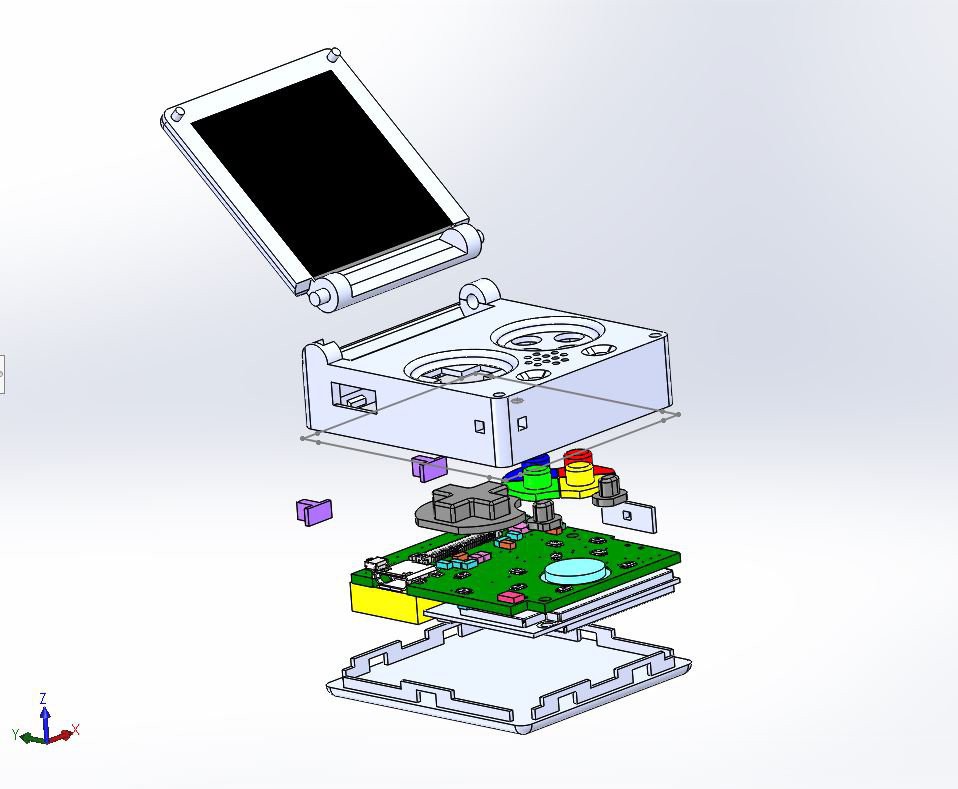
  • Mechanical design

    c.Invent10/12/2017 at 15:42 0 comments

    Before starting, you can find all the Solidworks source files from the project files or directly here.

    This log is not about 3D printing Keymu's body (there will be dedicated build instructions) but about presenting the mechanical design and discussing the different main parts. The design is fully functional but there is a lot of room for improvement, as you'll see. In fact we are currenty working on improving this design thoroughly for the next iteration. 

    Solidworks

    Why Solidworks? I know Fusion360 is the big thing right now but I simply already had a bit of experience with Solidworks so I simply went with what I already knew. So without further ado, lets jump into the design.

    PCB

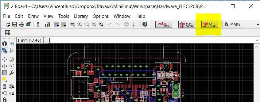
    First things first: before starting dressing it up, the PCB needs to be 3D modeled in the most accurate way possible. It is quite easy with Eagle to output an pretty decent 3D model of the board and components. Simply hit the "IDF to 3D" button in the board view and follow the instructions. 

    Even better is to set and fill an attribute "HEIGTH" to your components in Eagle before exporting to 3D, that way even if the components are modeled by bouding boxes, they'll automatically have the right height.

    The IDF file can be directly imported into CircuitWorks, and the bounding boxes simulating the components should be sufficient to develop the 3D case. However if you would like to makes things more real, most of the components 3D source files can be downloaded right from Digikey or from the constructors websites. Simply replace the bounding boxes by these models, this is what I did with the most important components: 

    As you can see I left the bounding boxes for the battery, the speaker and all the passive components (making sure they were the right height though). 

    Snap/fit

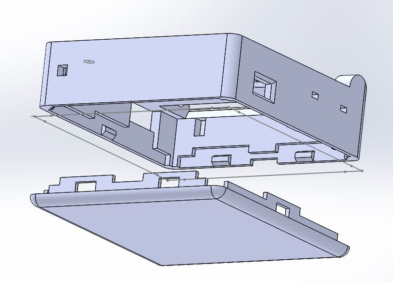
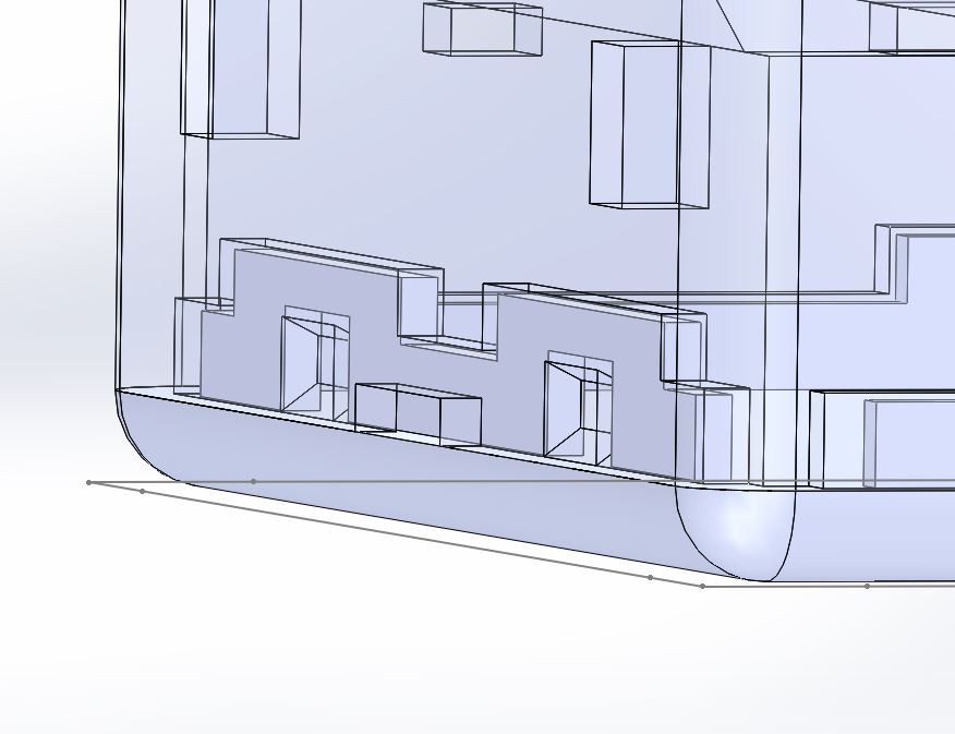
    Keymu is designed to be put together without screws, it's all snap/fit parts:


    I was a bit sceptic at first, thinking that there would be some wiggling or even fearing that the parts would break but with tolerances around 0.020mm I was very happy with the results. The bottom and middle part fit together really well, in fact they do not wiggle at all and I have tried throwing them against walls a couple of times, they do not break nor disassemble.

    Hinge

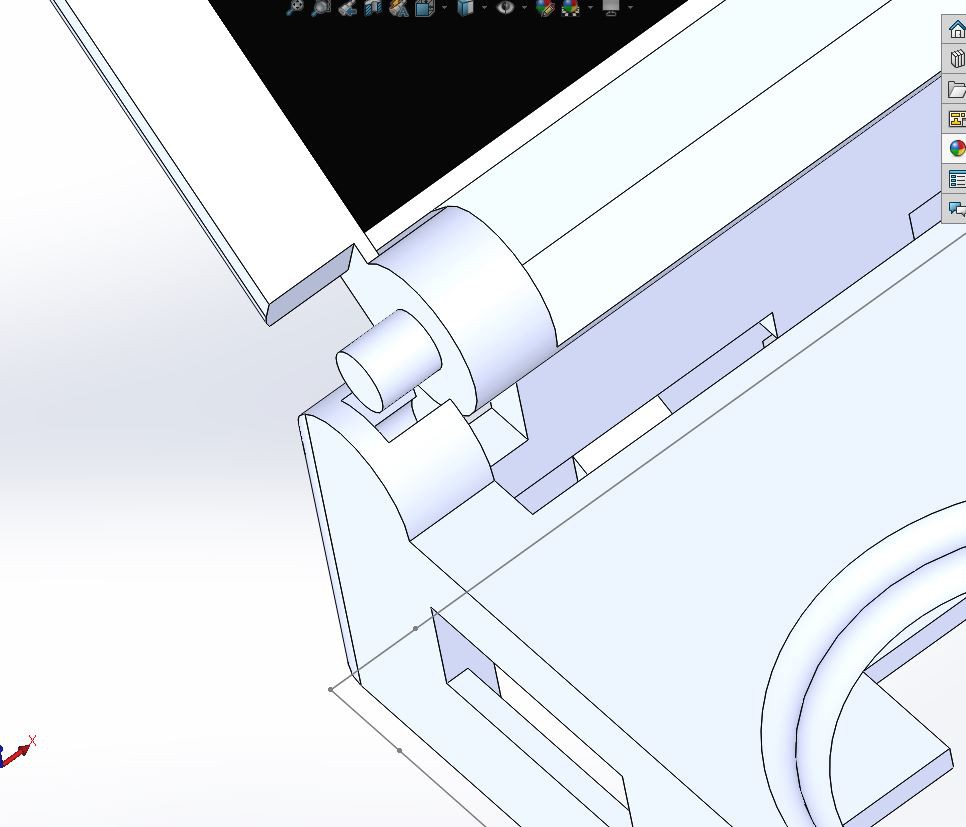
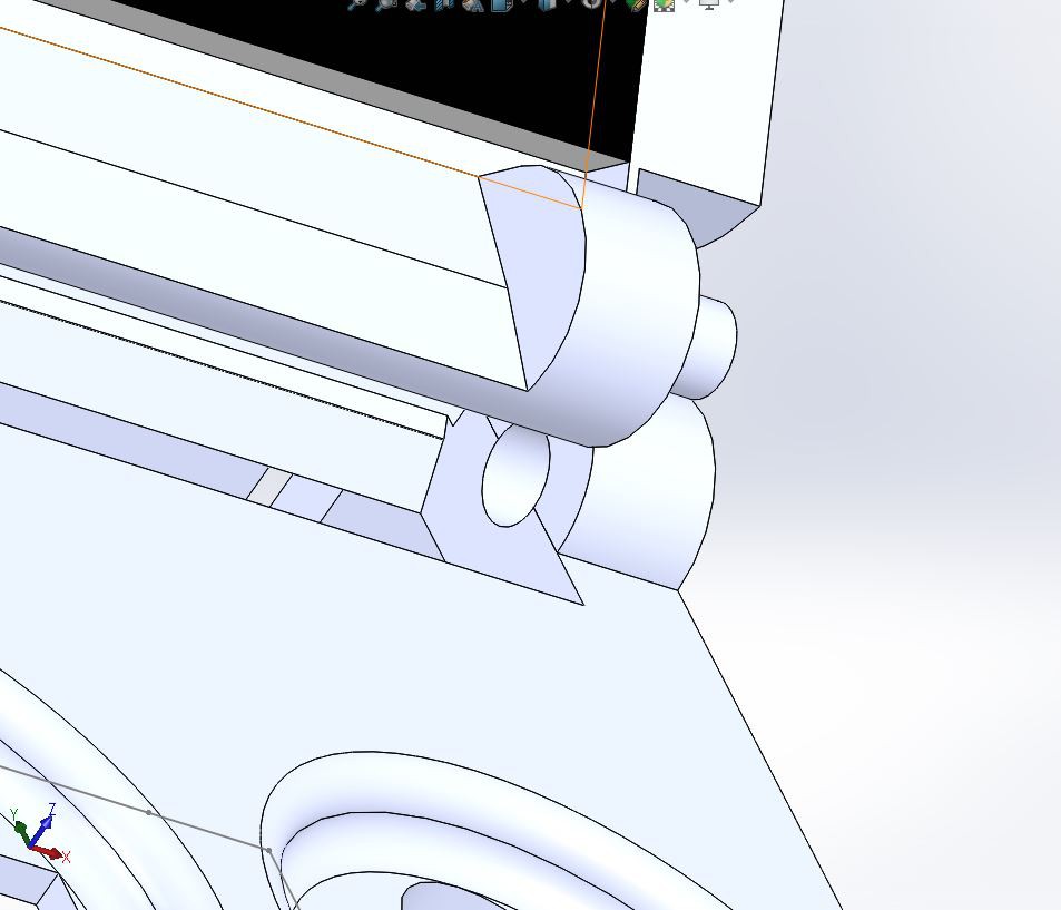
    The hinge was also designed so that its two parts - the screen casing and the main middle part - would slide in its socket on one side and snap fit together on the other:


    This is NOT optimal for many reasons: for starters it is obviously fragile, it is also not very easy to 3D print, there is no controlling the force of the rotation, and most importantly, the OLED flex cable is folded in two everytime the screen opens or closes.

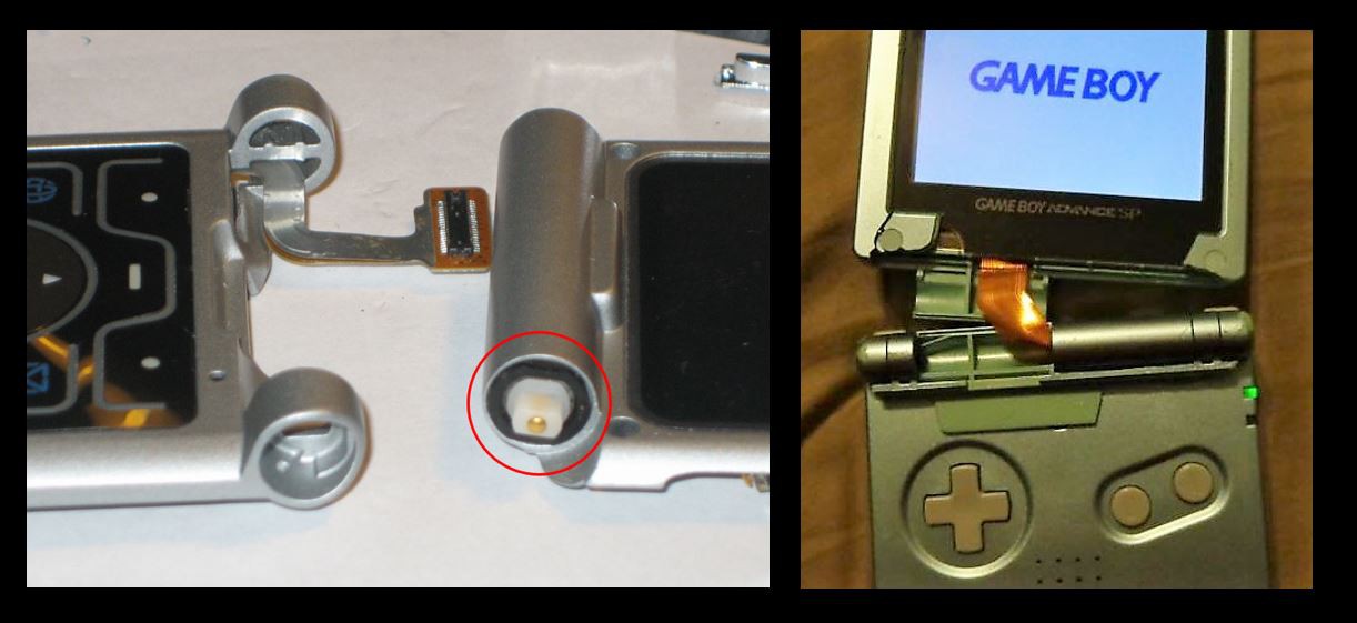
    So why what it designed that way? Well, if you look at how our old clamshell phones work or even if you open up a good old GBA SP, you'll see that most of the "active hinges", that is to say hinges designed for passing electrical wires through them, are designed pretty much always the same way. The flex PCB of the screen enters inside the hinge part from one of the 3D case travels through this hinge part inside the hinge part from the other 3D case, and enters the other 3D case from there. Most of the time the flex cable inside the hinge parts is already rotated, so basically when you open or close the screen, nothing bends or folds, it just follows the already designed rotation. 

    This is all good and well but this means flex cables are designed especially for our needs and most importantly with a width of around 4-5 mm max proportionnal to Keymu. The 1.5" OLED screen in Keymu is sadly not designed for active hinges and it is 28mm wide...while Keymu's width is 42 mm. This leaves around 7 mm around each side of the flex cable, hence the choice of this simple but effective design instead.

    Main Buttons 

    The main buttons are independant and rest directly above the panasonic tactile switches. Same thing with the arrows, appart this time this is a whole block supported not...

    Read more »

  • BOM & Eagle Schematics

    c.Invent10/11/2017 at 14:26 0 comments

    First and foremost, this is my first PCB so please be indulgent.

    This being said:

    • You can download the schematics in the project files or here.
    • You can download the BOM in the project files or here.

    I prefer writing a log about this instead of build instructions, since this is more of a discussion of the schematics/BOM than proper build instructions. Of course, any comments/critics are very welcome so that Keymu can benefit from everyone's knowledge.

    Schematic

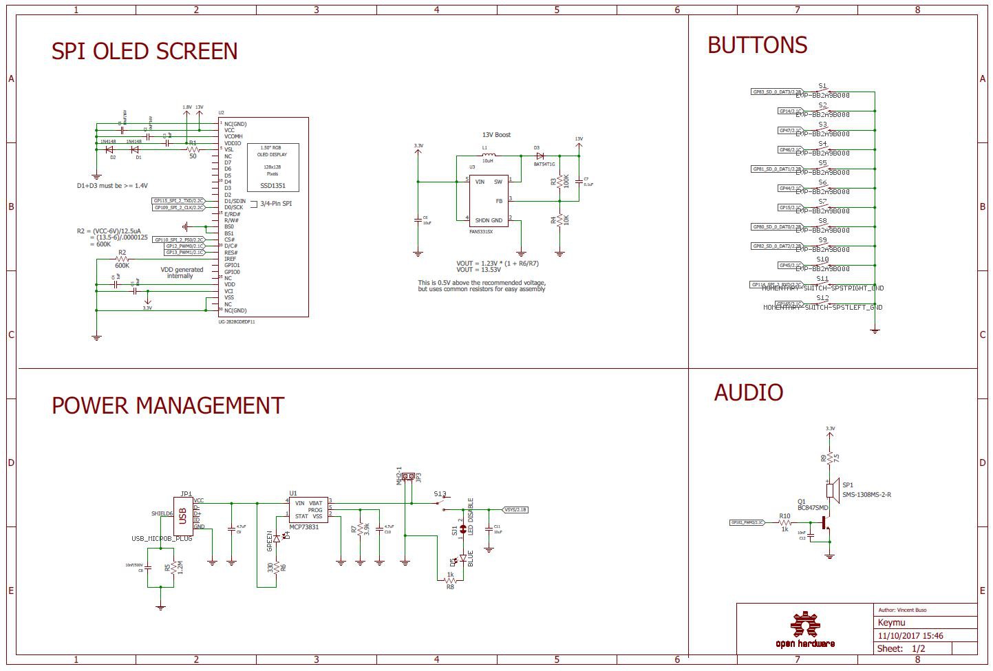
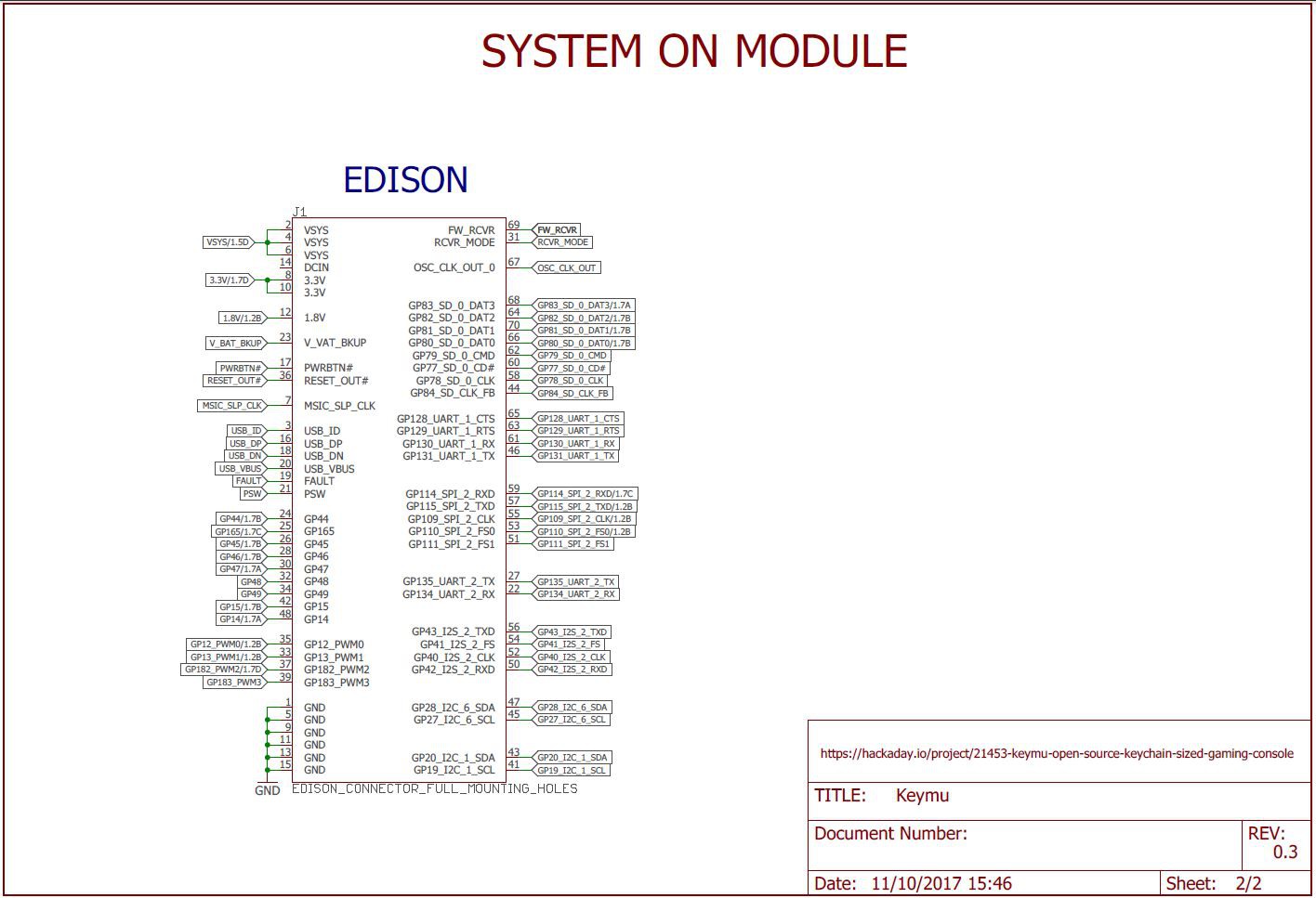
    Keymu was built around five mains blocks visible on the schematics:

    • page 1 : Power management, screen management, buttons, and audio
    • page 2: The Edison itself


    Power management:

    This block was mainly inspired from Sparkfun's Battery block for the Edison. 

    Basically there is a MCP73831 linear charge management IC which does all the job of charging the battery from the micro-usb port. There is also a power switch to turn on/off the supply of current to the rest of the system (while still allowing the battery to charge), a blue LED to indicate if the system is turned on and a green LED that lights up when the battery is fully charged.

    The few changes from sparkfun's battery block are :

    • RC circuit with high supported voltage connected between the micro-USB shield and the ground to handle electrostatic charges,
    • Changed R7 resistor value to charge 220mAh batteries at 1C.

    Screen block

    This block is almost fully based on adafruit's 1.5'' OLED Breakout Board. The only difference here is the VDDIO input signal of the screen which is set to 1.8V (instead of 3.3V) which is the Edison's GPIO's working voltage. The screen is also powered by the 13V boost converted and communicate with the edison through SPI.

    Audio Block

    Even though the last version of Keymu does not output audio, it is not the hardware's fault but the developer's one (guilty). The hardware is all there, and now Keymu needs the corresponding Kernel drivers to drive it. There is no DAC on the Edison so the chosen solution was to drive the speaker through a transistor delivering 3.3V with a PWM signal. Even though the sound quality is not the greatest, this is a well known solution and costs way less space (and price) than driving an external DAC with I2S. There is a great article about PWM audio in Make magazine, and this is the solution used for the Edidoom project as well, where it can be seen that the sound quality is not that bad, especially keeping in mind that the final product is a keychain.

    PushButtons

    Not much to say about this part, this is pretty much simply a matter of connecting the switches to the edison's GPIO's on one side and ground on the other. This is possible since we use the internal pull-ups of the edison allowing to save space and an easier rooting.

    Board layout

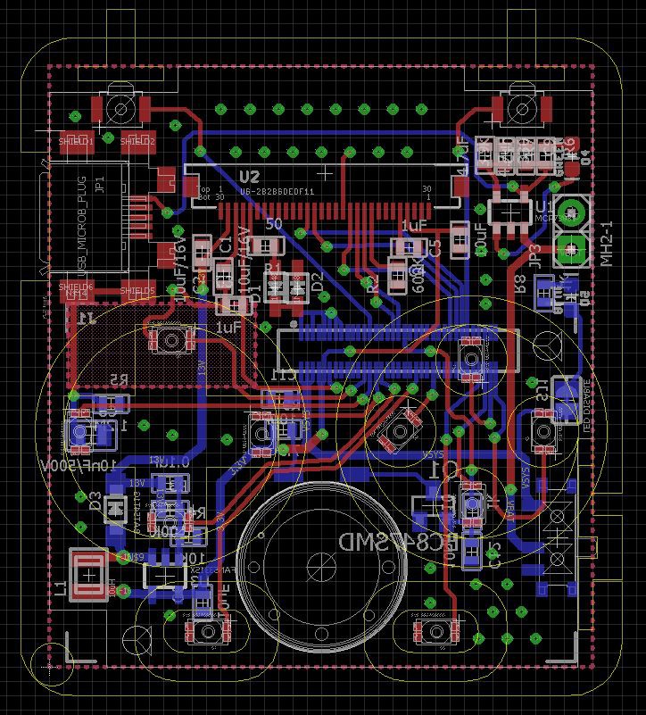
    The full board layout can be seen on the following snapshot:


    This is a bit of a mess to untangle so I will be discussing the top and bottom parts separately in the following paragraph. One thing to notice though is the yellow superposed drawings of the mechanical design for the casing and the buttons. 

    Top side

    For more clarity here is the top part of the PCB:


    It can be divided into two main parts: the higher one and the lower one. The lower one is mainly dedicated to the pushbuttons. It is quite had to find some space for other components in this part because otherwise it could prevent the full course of the mechanical parts above the pushbuttons.

    The higher part is dedicated to the microUSB on the left, the screen connector and dedicated components in the middle, and power management with battery connector on the right.

    Bottom side

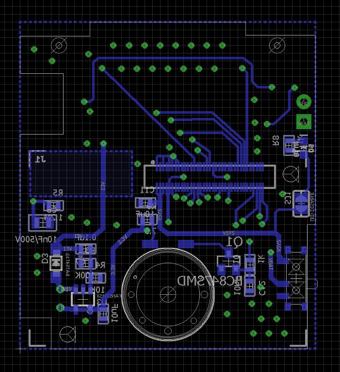
    and here is the bottom side:


    Here again it is divided in two: this time the lower part contains the Edison connector and all the components under the Edison: 13V DCDC boost convertor on the left, audio block on the right of the speaker and the on/off switch on the right. The top part is totally free of componnents on purpose: this is where the battery is located.

    I know the writings...

    Read more »

  • A bit of catching up

    c.Invent10/11/2017 at 11:33 0 comments

    Since the last project log ended with "This is it for this first log, the next one will be, I think, about describing more in details the advancement of the project and giving the roadmap", one was not wrong to expect more logs or build instructions to be posted soon after.

    But since then nothing...how in the hell did this happen ?

    Was this all a lie ?

    Of course not, and this log is dedicated to give updates and explanation about what happened these last months, because - in fact - many things happened.

    Let's start from the beginning, Keymu was originally a side project to learn electronics/embedded systems. As it is explained in the project introduction, I fell in love with Sprite_TM's micro Gameboy and realized I could learn a lot by making one myself. And learn I did: making my first PCB, modifying and recompiling the linux kernel, building a dedicated debian distribution, 3D modelisation and 3D printing... all this was new to me. A few months later and with the support one genius of a colleague, Keymu was born and I started this entry on Hackaday. 

    I figured participating in the Hackaday Prize 2017 would give Keymu some visibility and - oh my god - it did, way beyond what I had expected. 

    When things get out of hand - in the good way

    Just after Hackaday's article on the Intel Edison being discontinuited, a Danish journalist contacted me about Keymu basically to write about how Intel's announcement affects people and existing projects. He asked me if I had a small video showing Keymu in action so this is when I shot the very unpolished youtube video you can see in the introduction. 

    This article was not really about Keymu though, in fact, it was entitled "One of the victims of Intel's IoT retreat" - not very glorious... However, a few weeks later, Hackaday wrote its own article about the project, like it does for many projects in the Hackaday challenge 2017. This article led to another in BoingBoing, which led to another on Gizmodo, which led to many others. 

    We (my genius colleague - now partner - and I) even were invited on an live show by a Youtube channel in France called Geekinc where they interviewed us about Keymu (interview in French): 

    All these articles were a very nice unexpected surprise, and led to many views on this page, as well as many views on the youtube video (which is now monetized, allowing me to recover a little bit of the various costs of making the prototype). 

    But most importantly, all these views and comments led me to realize that many people were interested in Keymu and wanted one (some unanswered comments on Youtube even proposed that I simply named my price to buy some). 

    So, where do we go from there? Well, let's product some Keymus !

    Production baby

    Yes that's right, Keymu is now on the road to becoming a real product but the road is still very long. One does not simply jump the huge gap between homemade prototype and production-ready device, but even before that many issues need to be solved with the current prototype:

    • Keeping the Edison is not an option now, this means rethinking the whole harware,
    • Developing a new linux distribution, very lightweight and optimized this time,
    • Rethinking the whole mechanical design, most specifically the hinge...
    • Adding working audio,
    • and many other things...

    This is without counting all the new difficulties added by entering production, certifications, legal issues, starting the crowdfunding campain... So I officially parnered up with my genius colleage and we have both been working hard on the new product for the last months or so, and continuing to do so... hence the lack of activity on this page for a long time.

    Excuses, always excuses

    Juggling between daily work, Keymu new objectives, and - well - life, meant little time to post long and detailled tutorials to build Keymu like I initially planned but a promise is a promise and I will be releasing (with less details) the Edison Image, Eagle files, BOM,...

    Read more »

  • Block diagram

    c.Invent04/26/2017 at 16:18 0 comments

    At the time when these lines are written, the project prototype has been fully validated except for the sound. Granted, design-wise the prototype is much closer to a bomb than to a keychain, but believe me, after all the work it involved, it has never been so rewarding to play some good old fashion SuperMario Kart (GBA).

    However there is some catching up to do before getting into the fonctional prototype.

    This first log describes the main components of this project:

    • Let us start by the most important component: the processing unit. After looking online for the best fitted computer module (nice comparison of modules at the end of this page), I believe the most suitable solution can be found in the Intel Edison module. For around 50$, you have a module of 35.5 x 25 x 3.9mm with a beefy dual core 500Mhz processor (based on an x86 architecture), 1GB of RAM, 4GB of flash storage on board, bluetooth, wifi, a power management unit, and many interfaces: usb, sd card interface, SPI, 2 I2C, 2 UART, I2S, and 12 GPIOs.
      Agreed, it is expensive but it is either this or building its own processing unit (which I simply do not know how to do), or opt for a way bigger solution. I sincerely hope Intel will decrease the price of their module, especially since it is out for some time now.
    • The second main component of Keymu would be its screen. For this part I realized very quickly that, as for the processing unit, there were not many possible solution available. The size constraint makes it only suitable for screens up to 1.5" to 1.6" maximum to be considered. The Edison does not have display interfaces such as MIPI or MCU, so the only way to command and send data to the screen was with SPI. With difficulty, it is possible to enable DMA on the Edison (I'll get into this later), allowing to communicate in SPI up to 25Mbit/s. Using RGB 565 (2Bytes per pixel), at 25fps, the maximum squared resolution reachable with SPI is then given by sqrt(25000000/(2*8*25)), that is to say 250x250. Other requirements were the display depth and the minimum size of the flex connector (it had to be long enough to turn around the hinge). After searching everywhere I could think of, I could not find a screen meeting all the criterions. The closest I found was an SSD1351 OLED screen but a concession had to be made on the resolution since it is only 128x128. There is a very good point to this screen tough: it is very easy to prototype with since Adafruit sells its very own breakout board.
    • The rest of the components are represented in the block diagram above. They were relatively easy to find once the final design was decided so I will not spend too much time on it. The only thing I would stress out is that "easy to find" is never given when building a product so small. Everything need to be thought of in advance, and my advice is to have a VERY good idea of your final design before getting the components and vice-versa when building the design. Yes it is a vicious circle but it is the way of small, optimized packages such as Keymu: the mechanical design and the choice of components are interconnected and need to evolve at the same time.

    This is it for this first log, the next one will be, I think, about describing more in details the advancement of the project and giving the roadmap.

View all 5 project logs

  • 1
    Flashing the Keymu precompiled Image on the Edison

    Download link

    The precompiled Keymu image is too big to be uploaded directly on hackaday (which does not support files higher than 50MB) so here if the google drive link:

    https://drive.google.com/open?id=0B73FmvhZdYr6MmE2eS02ZEp1Q1U

    Flashing the Image 

    Once you downloaded the zip file, you can start by unzipping it in the folder of your choice. It should contain a folder called "toFlash" containing all images and files required to flash the Edison.

    Using Linux

    Easy peasy japanesey: 

    cd toFlash/
    sudo apt-get -i install dfu-util libusb-1.0-0-dev
    ./flashall.sh

    It does not always work with virtual machines though, hence the other option:

    Using Windows

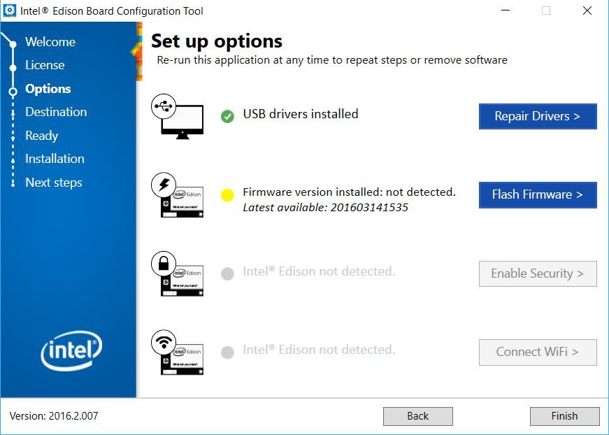
    There is also a dfu-util binary for windows available but I suggest you just download intel_edison_setup_win_v2016.2.007.exe from the Intel page:  https://downloadcenter.intel.com/search?keyword=edison

    Launch the software and this window will open:


    Click on next several times until you arrive at this window:


    Here you need to choose the second option: "Flash Firmware". 

    On to the next window:

    Select the second option "Use existing image, located at:". This is here that you need to specify the path to your FlashEdison.json file, in my case: C:\Users\VincentBuso\Desktop\toFlash\FlashEdison.json.

    Click on next and you will be prompted to plug in your Edison if you you did not already. Wait for about 5 to 10 minutes and Voilà, Your Edison is freshly flashed with the Keymu precompiled image.

    Let's try to turn it on...

    Start playing

    Assuming you followed log 3 until the end and you have a fully soldiered PCB at the ready (battery and all), you can now plug in the newly flashed Edison, turn on the switch and pray...

    Now the blue LED should already turn on, but the screen will need around 20 seconds before starting... just be patient. 20 seconds can seem very long when you are waiting in full anticipation but don't start biting your fingernails yet because - hey look - it works !

    Congratulations ! You now have a fully working prototype of Keymu, now let's dress it up.

  • 2
    3D printing

    The STL files are available on Thingiverse or directly from the project files.

    These STL files are for 3D printing or visualization, if you feel like modifying the 3D design and missed Log#4, don't worry: all the Solidworks source files are available here.

    No 3D printer, no problem

    I am aware not everyone owns a 3D printer, in fact neither did I when I built the first prototype. Platforms like 3DHubs for finding people around you with 3D printers exist and work really well. The casing you see in the youtube video showing Keymu in action has actually been printed by a previously unknown neighboor of mine that I met on 3Dhubs. Another alternative is to find an hackerspace next to your place where 3D printers are available.

    Of course if you plan on reworking the design, then I would suggest having a 3D printer at hand: unless you have extraterrestrial skills you won't have everything right the first time, or the second, or the third... So it's best if you can launch prints incorporating your new little modifications whenever you want. Another great advantage of owning a 3D printer is having complete control over your Slicer software/settings. This makes a huge difference

    Slicer software 

    The slicer software is basically what will translate the STL file into gcode: your printer's language. Nowadays slicer softwares are much more than that and configuring a print right can make all the difference. 

    I warmly recommend using Simplify3D as your Slicer software, it gives you a lot more controls over your prints, and most importantly over your support materials.

    General stuff

    Keymu was designed to be built without screws, only snap fit parts, this implies several things:

    • Keymu is small, and details matter at this size, I recommend printing at 100um or less if your printer can do it, and I also recommend having a heated bed.
    • When designing your 3D files, be sure the intricate parts have a tolerance of at least 200um.
    • When choosing your material for printing, be sure to get one designed for small details. The standard PLA from rigid.ink worked very well for me, and I refer you to filaween to find your best pick.

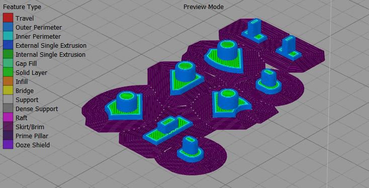
    Another thing that made all the difference during the prints was adding a skirt with 0mm offset from the parts, and variable length depending on their function. For exemple they are great for parts that have fileted edges right from the first layer, instead of adding support material to support the little overhang part at the begining of the filet. They are also great when printing the buttons, which are very small parts, all at once: it creates an interconnecting layer between them, so they will be less likely to move or fall out during the print.

    Support material

    Support Material is necessary for many of Keymu's parts, this is when Simplify 3D stands out from the other slicers: automatically generated supports are almost never perfect, and Simplify 3D offers you the possiblility to add or remove supports manually. 

    For Keymu's support materials I would recommend default settings appart from these values:

    • 4mm support pilar resolution (easier to remove while still close enough for overhangs)
    • 2 or 3 support base layers
    • No dense support layer
    • Two perpendicual support infill angles ([-45°, 45°] or [0, 90°])

    One STL at a time

    This is the part where you can find the Slicer configurations that worked best for me. I do not claim providing the best one, it depends on many things, starting by your 3D printer itself.

    The parts that don't need support

    Assuming your printer's resolution is around 100um or less, the following parts can be printed without issues since they do not require any support:

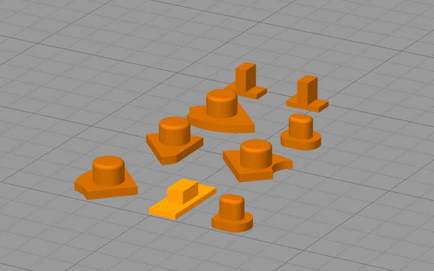
    • Keymu_A.stl
    • Keymu_B.stl
    • Keymu_LR.stl (x2)
    • Keymu_OnOff.stl
    • Keymu_Select.stl
    • Keymu_Start.stl
    • Keymu_X.stl
    • Keymu_Y.stl

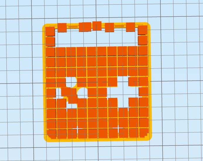
    Just print them on the following sides:

    And don't forget to add the skirts (here with 15 outlines so that the part interconnect)

    Also for this print you need to turn on retraction for the nozzle otherwise you'll have plenty of unwanted spider webs between your parts.

    The lighter orange part is the on/off button, it is hollow inside so there is an overhang but it is so small that it shouldn't pose any problem if you have a good quality filament and decent ventilation on your nozzle.

    The arrows

    Now we are getting started with the parts that do require support material, starting by the arrows. Because of the spherical part under them, the arrows need to be printed from top to bottom.

    The skirt is not necessary here, I'm just a big fan of them, they're never too much.

    The screen case

    The support material should only be necessary for the parts that enter the hinge on both extremities, since here the skirt helps supporting the overhang at the start of the fileted edged.

    The main part

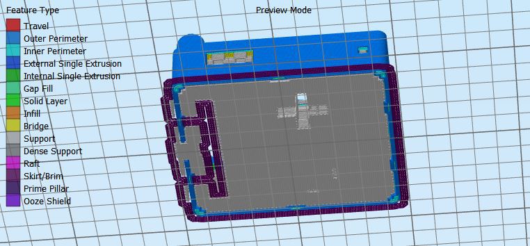
    This one is the hardest to print. I found that printing it from the bottom up rendered the best. Because of the snap/fit connection with the bottom part, there are overhangs on all sides, so be sure the automatic support generation does not forget them.

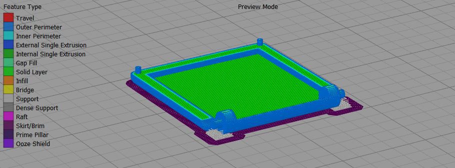
    For this part, I also suggest adding a raft (not present in the images below), it will make sure there is no warping on the bottom corners.

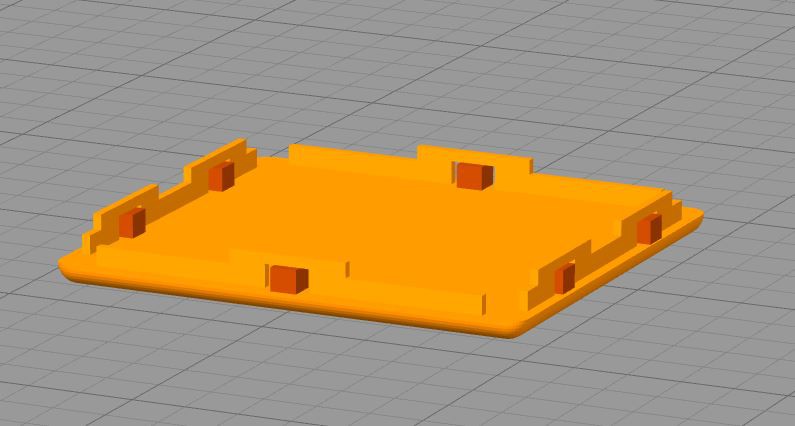
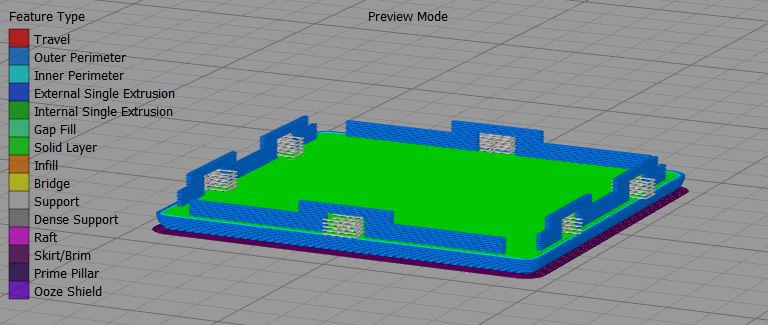
    The bottom part

    This last part is faily easy to print, just make sure there is support material under the overhangs for the snap fit parts and - as always - make sure you add a good old skirt.

View all instructions

Enjoy this project?

Share

Discussions

JAG wrote 08/11/2017 at 07:42 point

I'm a 10yo boy from OZ & I dont have a 3D printer, does anyone know how I can buy all the parts for this project ( with my Dads CC ) !!!

  Are you sure? yes | no

ninjacookie.clara wrote 07/15/2017 at 22:49 point

How do I get my hands on one of these? I'm new to the cite

  Are you sure? yes | no

jeffj wrote 07/12/2017 at 19:52 point

where is the source code?

  Are you sure? yes | no

Otokaze wrote 07/12/2017 at 04:04 point

When will the chips start?

  Are you sure? yes | no

??? wrote 07/11/2017 at 03:48 point

Which GBA/GB games will be on it? Will it have any Pokemon games, namely Fire Red/Leaf Green? Love the project by the way!

  Are you sure? yes | no

walsh111803 wrote 07/11/2017 at 03:40 point

what is the game lis

  Are you sure? yes | no

walsh111803 wrote 07/11/2017 at 03:39 point

what are all the games avail

  Are you sure? yes | no

vogtleon3 wrote 07/10/2017 at 17:51 point

When is the guide for the construction?

  Are you sure? yes | no

Anthony wrote 07/10/2017 at 14:32 point

Awesome project, is there a time frame for when instructions will be released??

  Are you sure? yes | no

ianwebstertx wrote 07/10/2017 at 13:57 point

this is awesome, I can't wait till the instructions are posted

  Are you sure? yes | no

w4ilun wrote 07/01/2017 at 23:41 point

Awesome project, great work!

  Are you sure? yes | no

peter jansen wrote 06/01/2017 at 17:21 point

Wow that's tiny!  Good work!

  Are you sure? yes | no

Squonk42 wrote 05/22/2017 at 20:11 point

Can't wait to have it in my hands ;-)

  Are you sure? yes | no

Ramon Imbao wrote 05/22/2017 at 13:53 point

Looks fantastic! Can't wait to build one myself.

  Are you sure? yes | no

c.Invent wrote 05/22/2017 at 17:57 point

Thanks Ramon!
The first "real prototype" was put together this weekend and - oh man - it looks even better when you have it in your hands (even though I am obviously not the most objective party able to claim such things).
I'm afraid there are still many little (and not so little) things that need improvements before I can put it out in the open though. Even for the Version 1.0, I would like something sturdy, beautiful and (a bit) finalised/optimized. In fact my next log will be all about that: what's left to be done or improved and most importantly what works today (with a nice video if I have the time)...

  Are you sure? yes | no

c.Invent wrote 04/27/2017 at 13:33 point

It was the idea at first until I realized I had no space for the speaker left. 
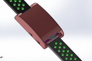
Even if they are really small, it was still too big (especially for the space under the right arrow and the X button). The only compromise I found was to opt for a round form factor, allowing to remove the angles taking space for the buttons.

Right now I am using this one:

http://fr.farnell.com/multicomp/mckp1227sp1-4721/transducteur-haut-parleur-rx-1/dp/2396076?ost=MCKP1227SP1-4721&selectedCategoryId=&categoryNameResp=Tous&searchView=table&iscrfnonsku=false

  Are you sure? yes | no

Similar Projects

Does this project spark your interest?

Become a member to follow this project and never miss any updates