-
Wheels!
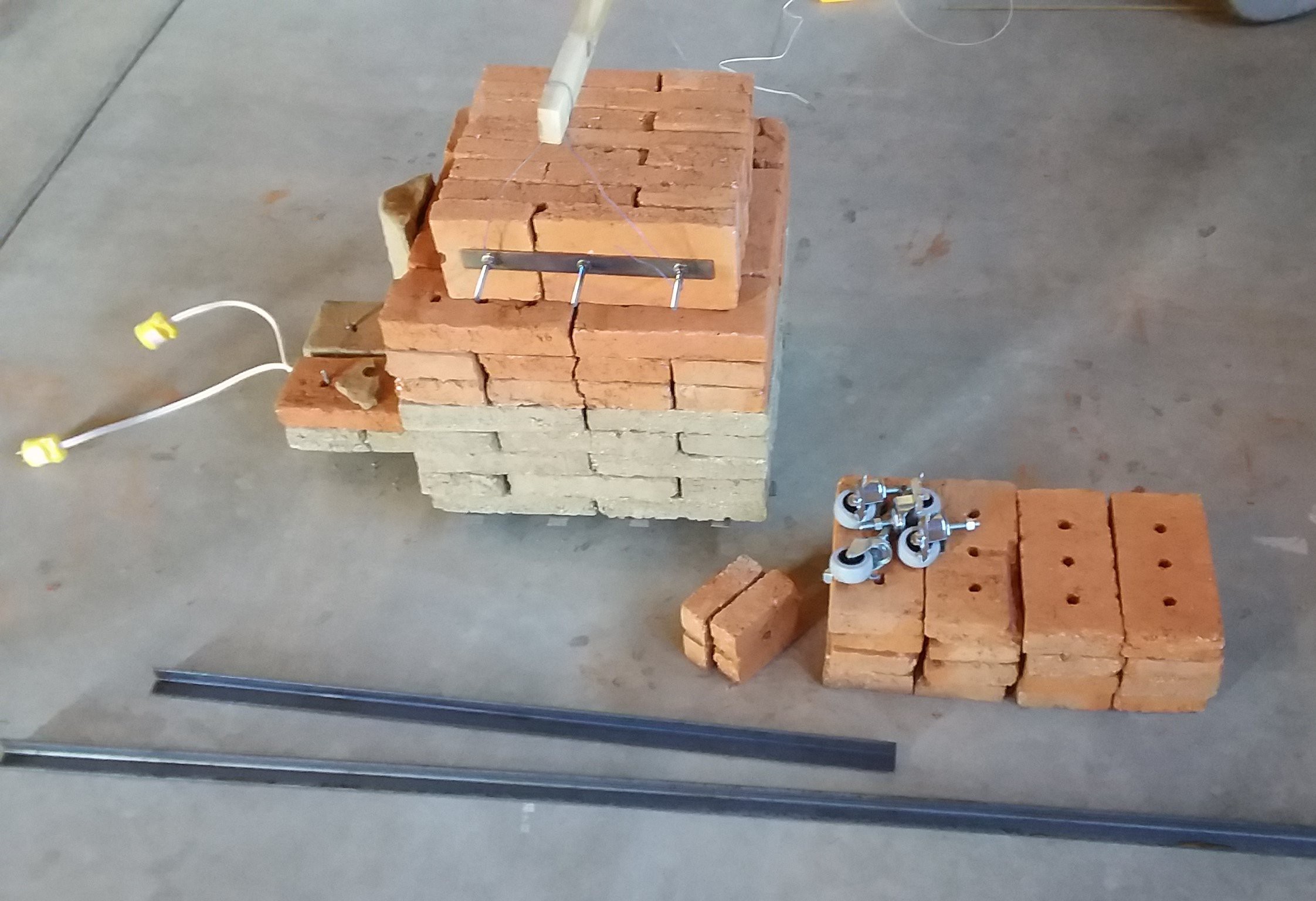
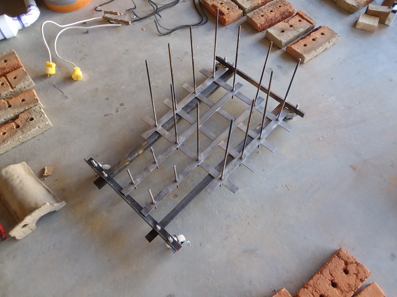
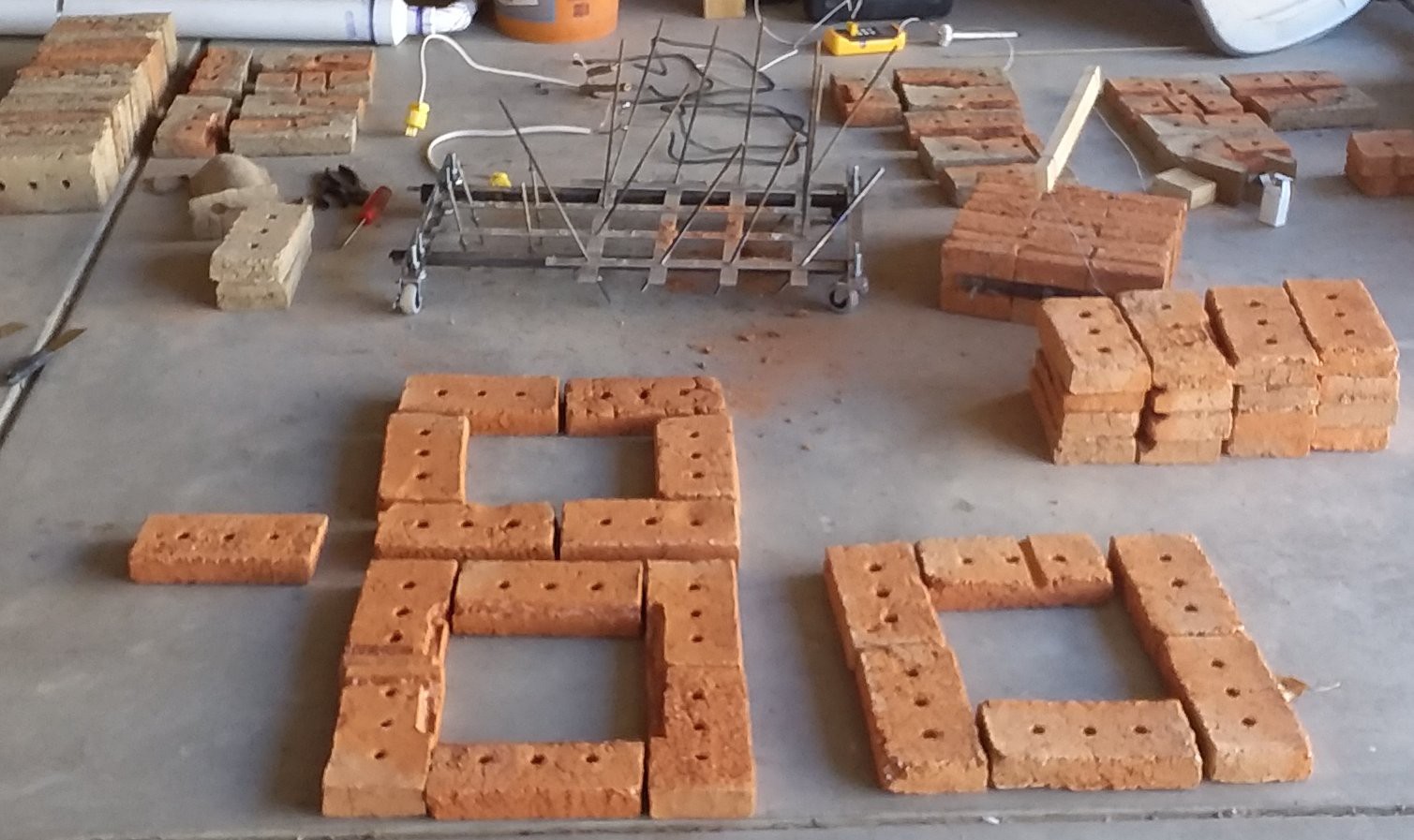
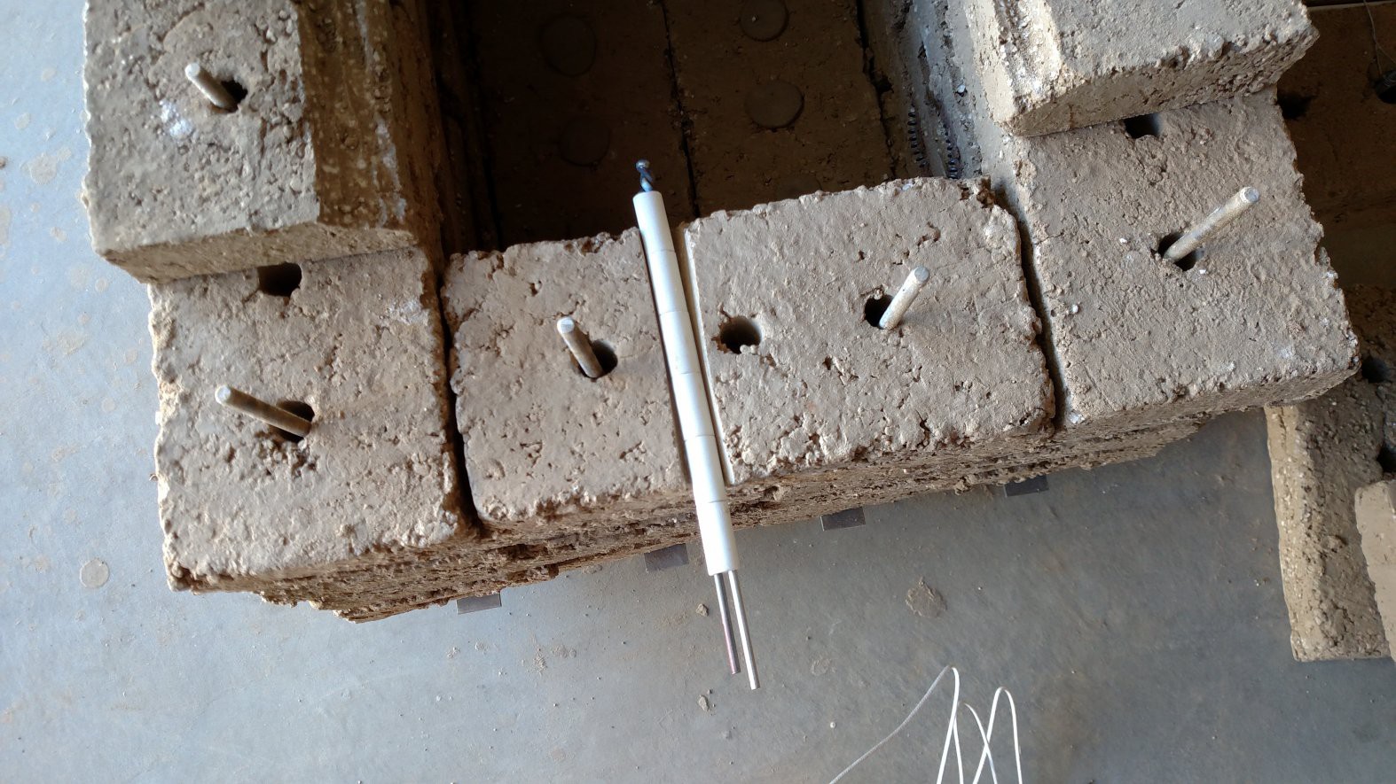
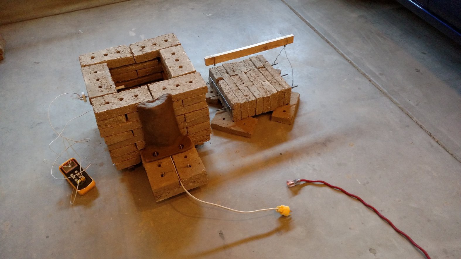
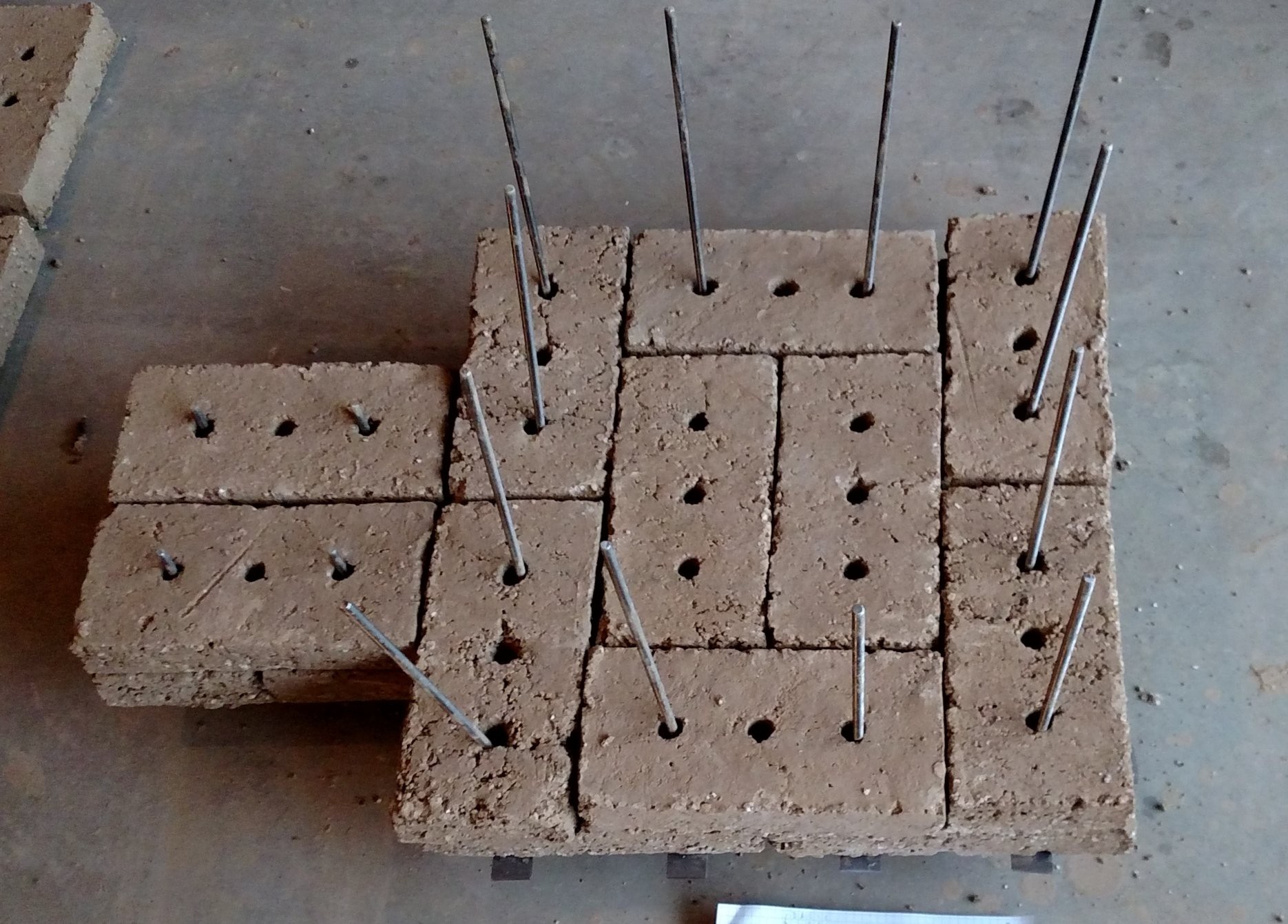
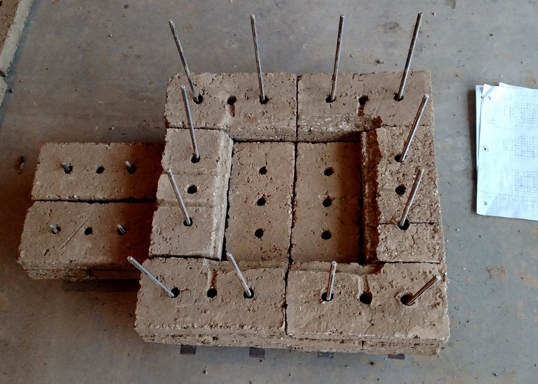
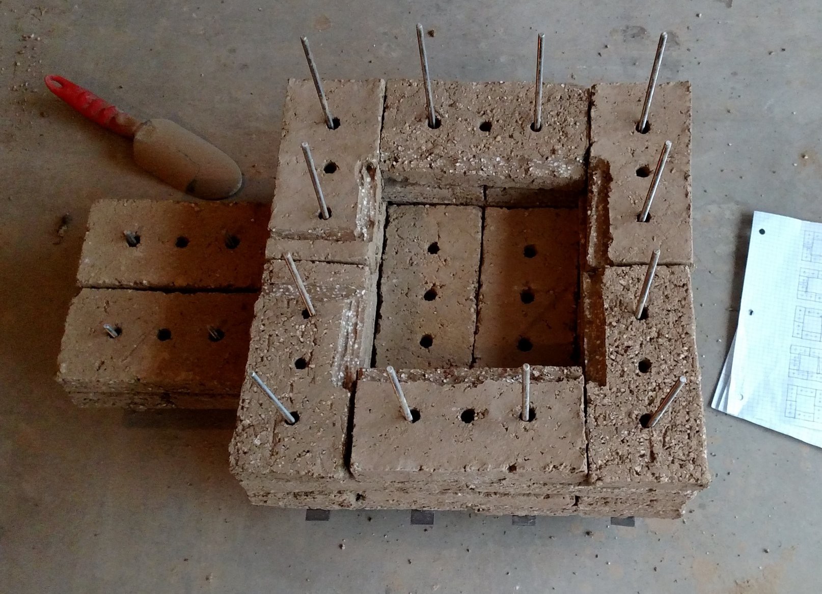
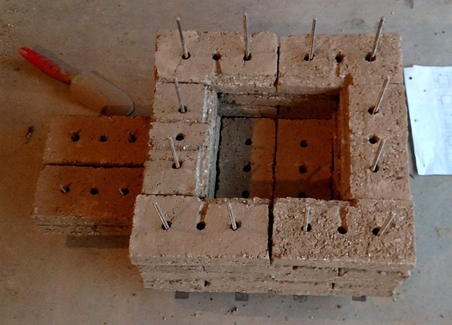
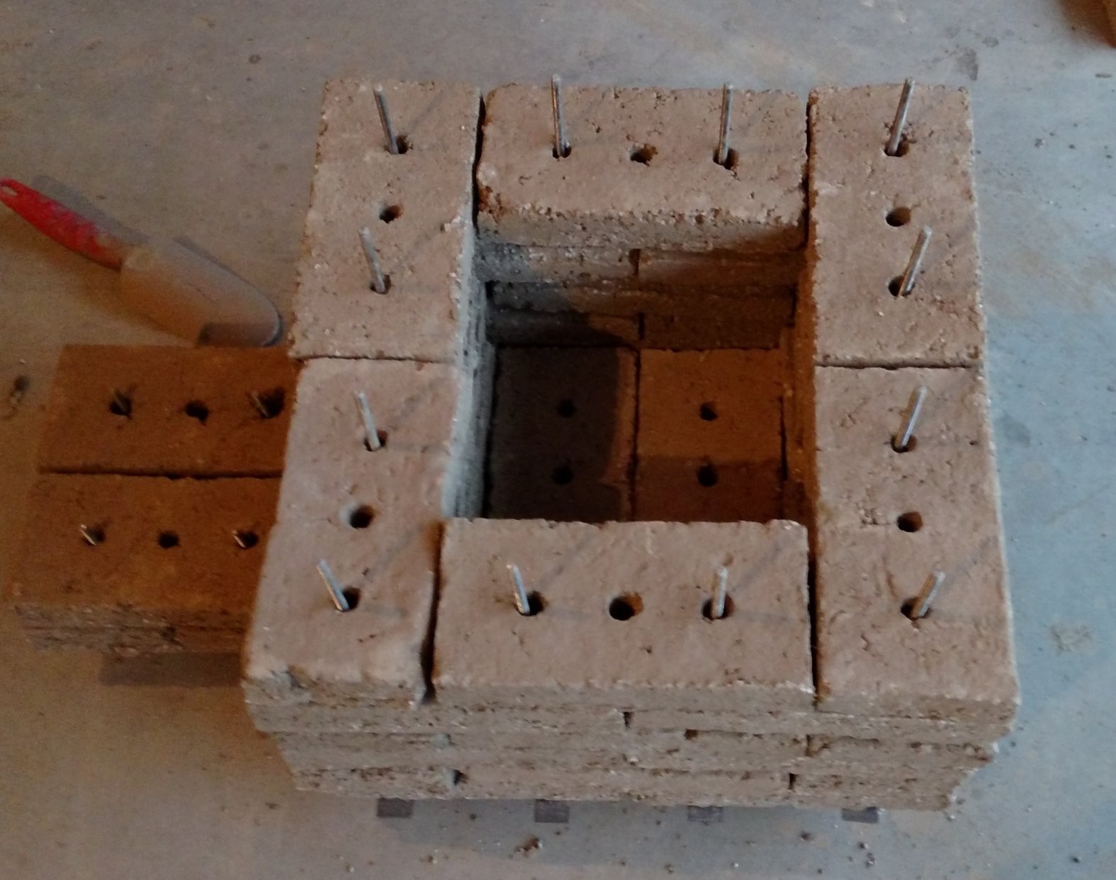
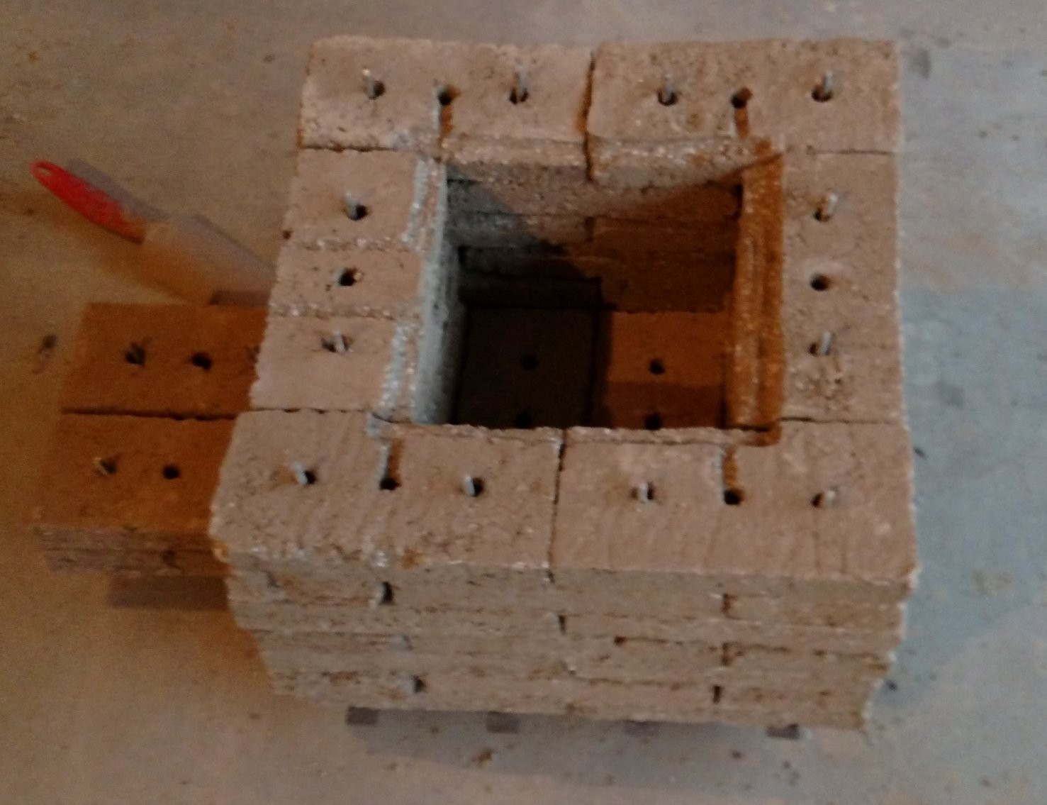
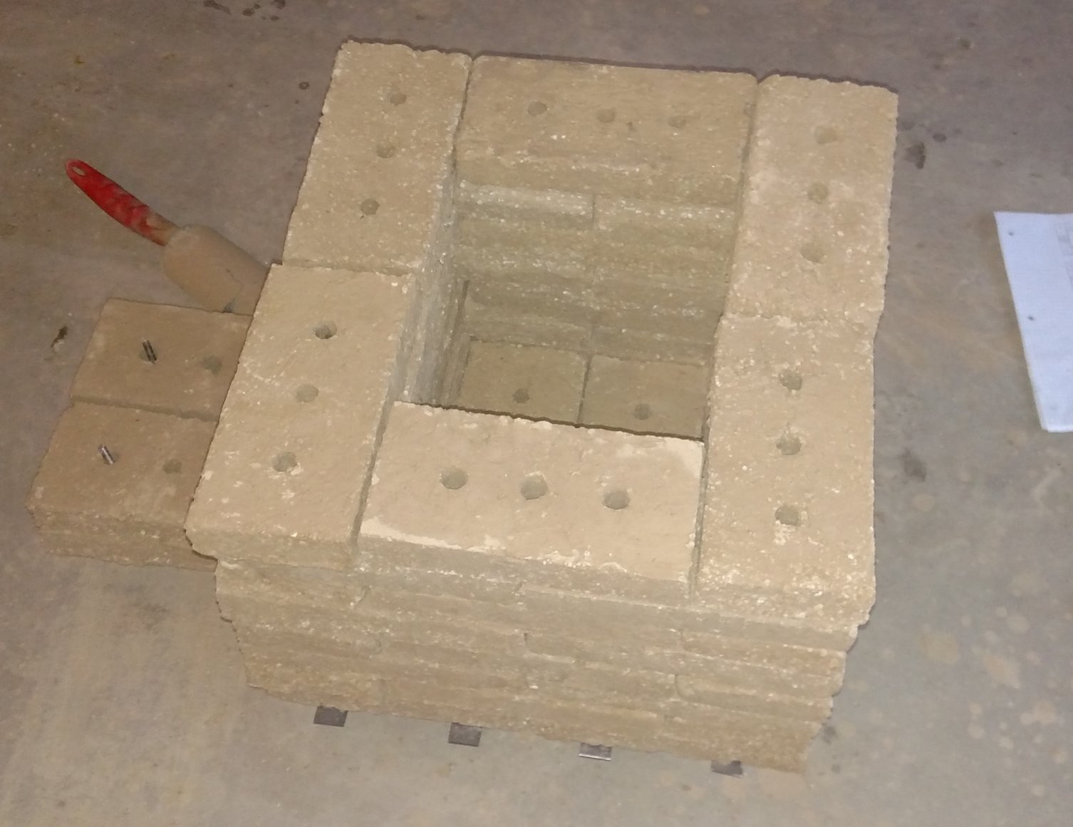
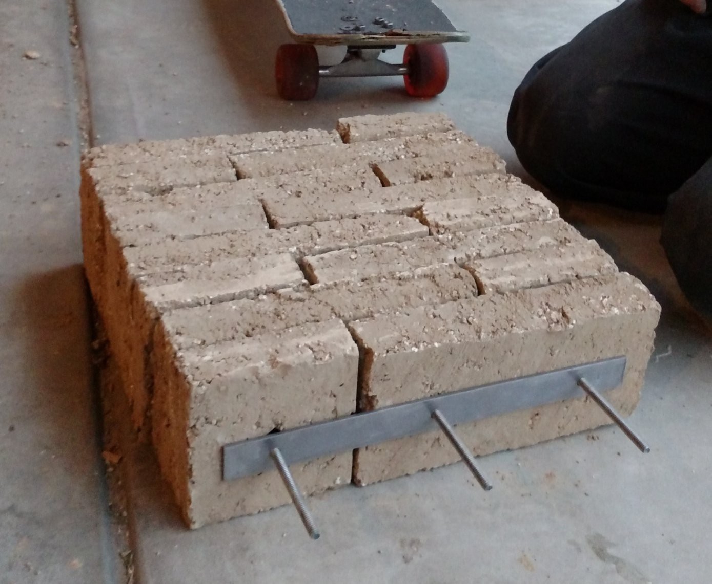
03/16/2018 at 05:21 • 0 commentsIt was time to move the car into the garage, so the kiln needed some wheels to make it movable. A mobile frame was bolted together using a few feet of 1 inch X 1/8 inch angle steel, and four standard locking caster wheels. This new wheel frame went underneath the existing brick support lattice. The entire kiln was disassembled, and then reassembled using fired bricks from the bottom up. The unfired bricks are now accessible and will be fired in sets of eight until the whole kiln will contain fired bricks.
![]()
![]()
![]()
-
Heater Considerations
01/21/2018 at 06:15 • 0 commentsBack in August 2017, when this project was mentioned in the Hackaday Blog, Hackaday reader [S] commented "Now he just need to check these bricks for low Fe2O3 and high Al2O3..." And reader [Dan] responded "[S] is correct the iron acts like a flux..."
[S] provided a link to a catalog with information on resistance heating alloys manufactured by Kanthal. In the section on Ceramic Support Material in the Kanthal catalog, it is mentioned that "Iron oxide (Fe2O3) content must be as small as possible, preferably below 1%".
This presents a potential problem for my kiln, since the deep red color of the bricks indicates a high Fe2O3 content. I do not know what the exact (or even approximate) iron content is, but it is a safe bet that it is quite a bit higher than 1%. I am also not sure at what temperature the iron content becomes a problem, but there is an interesting anecdote related to this in an internet posting called Lessons from a Kiln Repairman Down Under by Dave Coggins, in which the author built his own kiln heating element support plates using an iron-containing high temperature castable cement. According to the author, the support plates became electrically conductive at around 1100 degrees C (2012 degrees F) due to the iron content of the cement, and this caused short-circuiting and thermal runaway that resulted in a dramatic failure of the kiln. I don't know if this is the sort of failure that [S] and [Dan] had in mind, but [Dave Coggins] indicated that his iron-containing heater element supports worked OK below 2000 degrees F.
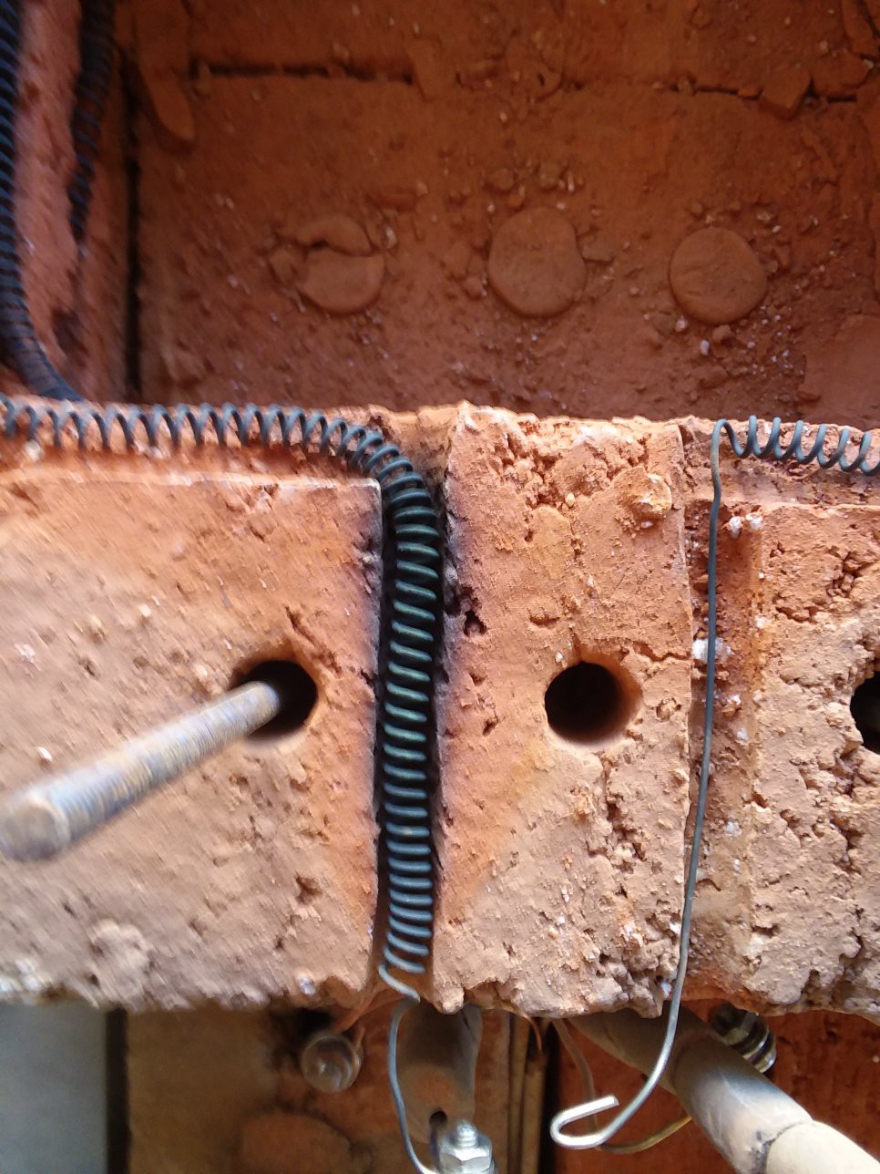
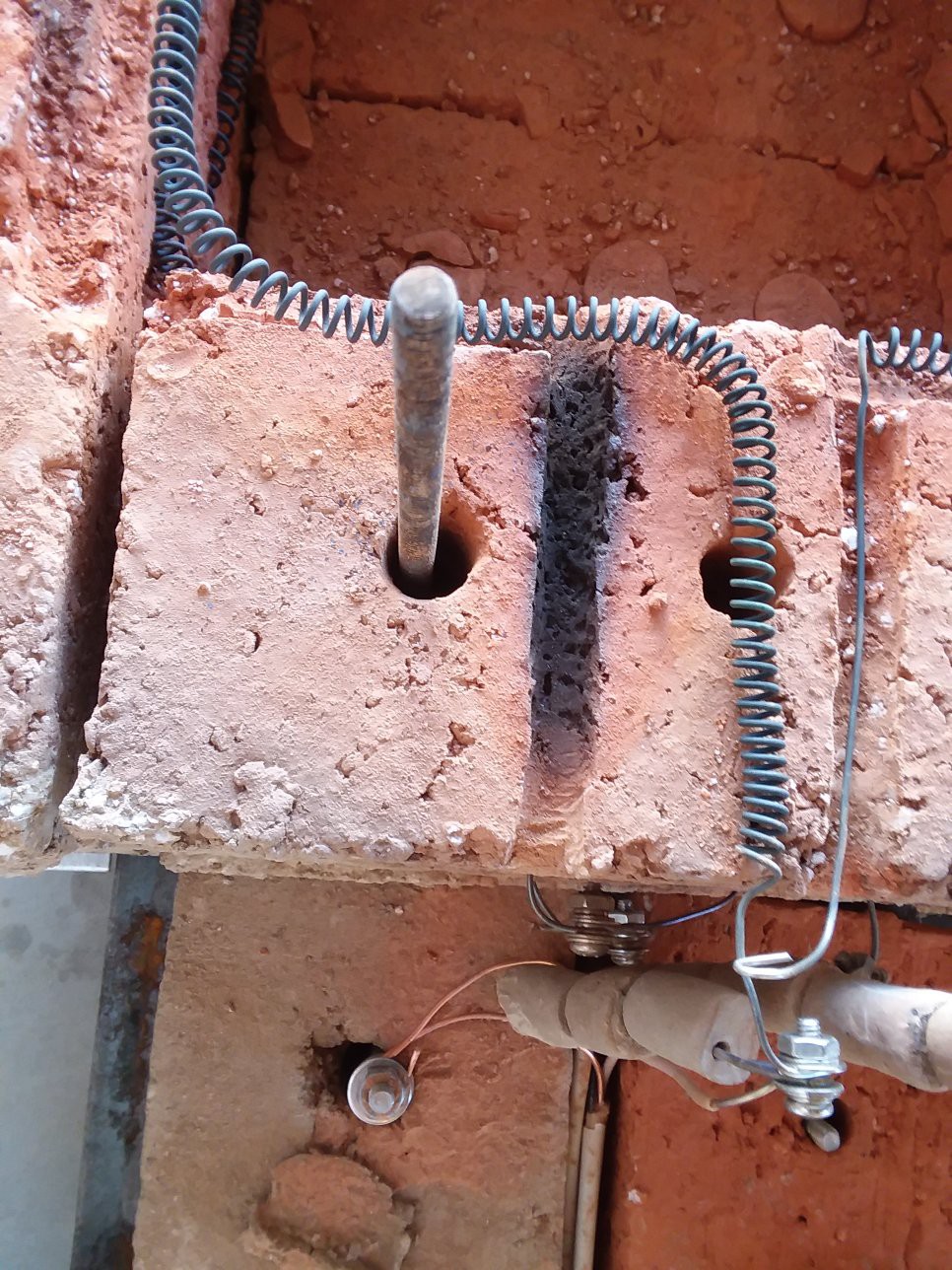
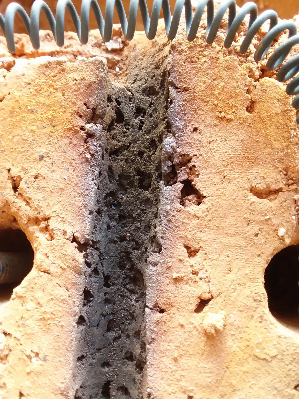
A separate issue from the "iron flux" one is that the natural clay bricks are experiencing heat damage in certain parts. This can be seen in the pictures below showing a section of grooved brick where a full heater coil passes through. Because the full coil is surrounded by brick here, the temperature gets much higher than that of the rest of the kiln.
![]()
![]()
![]()
It is interesting to see that it is almost like the Perlite has been boiled out of the brick... The temperature in this groove is much higher than it should be, so I should probably modify the heater element so it is just a straight wire instead of a full coil.
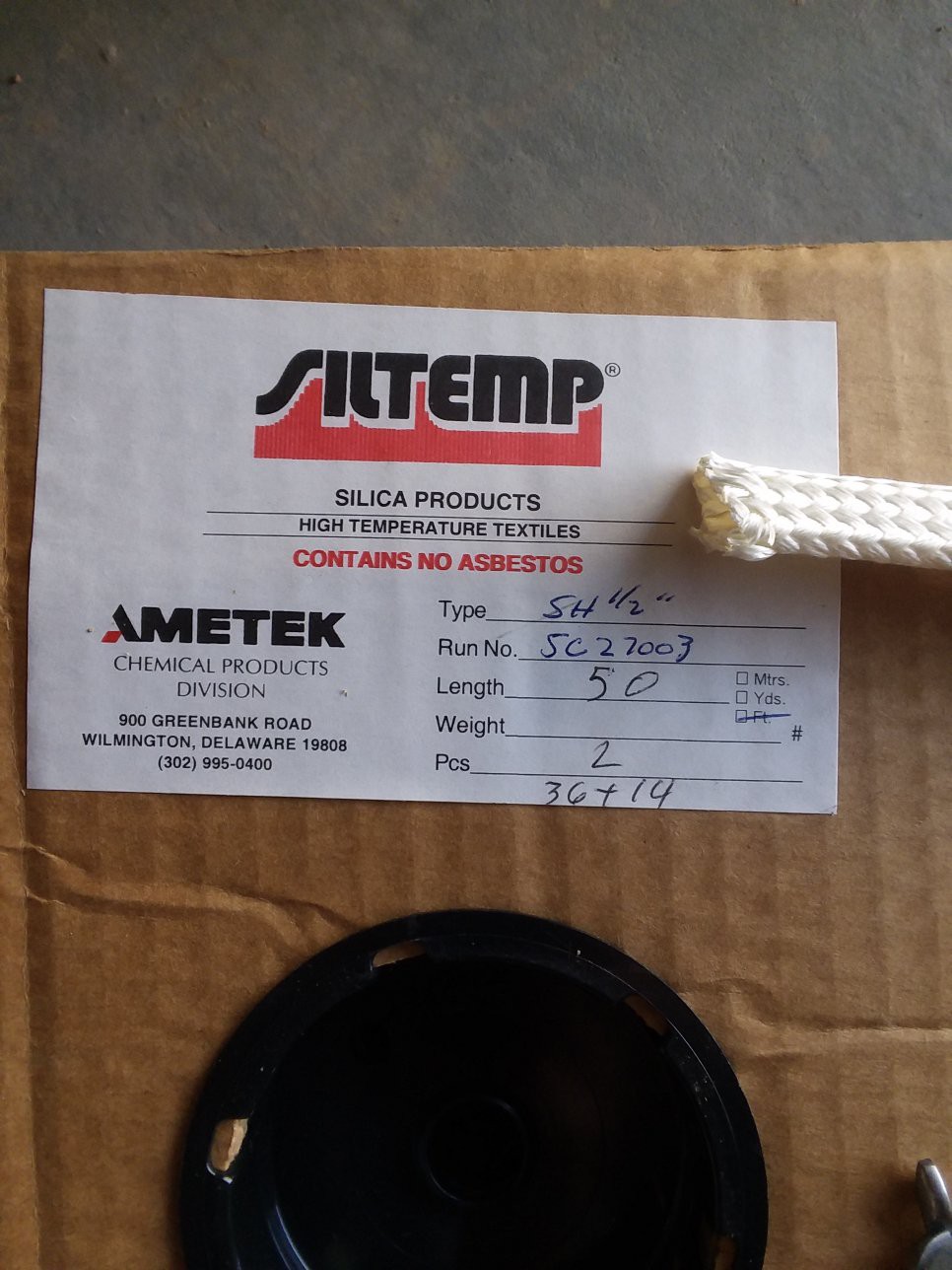
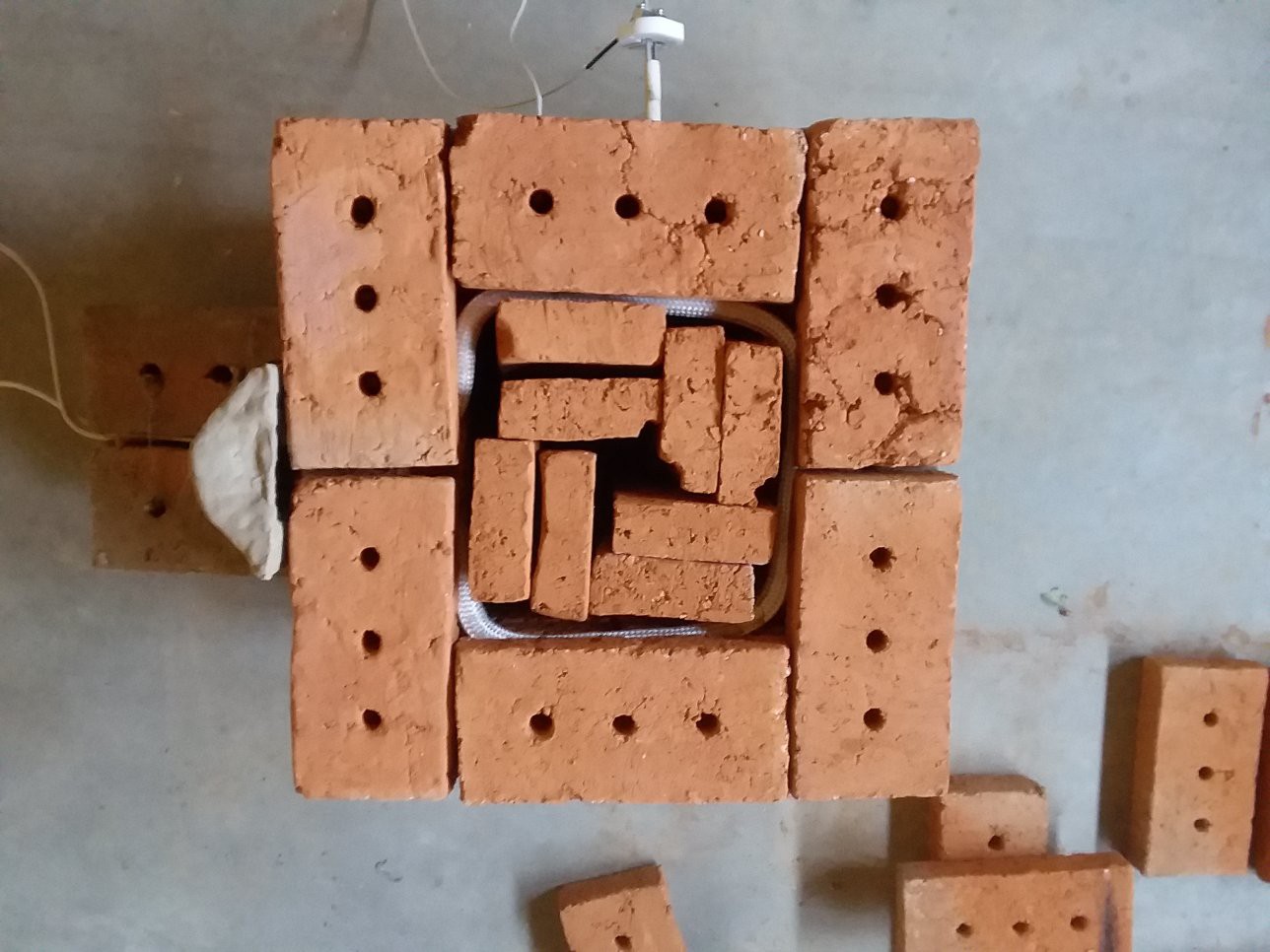
In an attempt to avoid further heat damage and also to isolate the coils from the bricks to avoid potential problems with iron, I tried installing a heater element is a flexible sleeve made of woven fused silica. I got a big roll of this stuff off ebay for $25 or so.
![]()
After much fussing around, I got one of the heater coils threaded through a piece of the woven tube. NOTE: I WORE RUBBER GLOVES AND A RESPIRATOR WHILE I DID THIS. The respirator might have been overkill but the material safety data sheet did say that handling the tubing could irritate the skin.
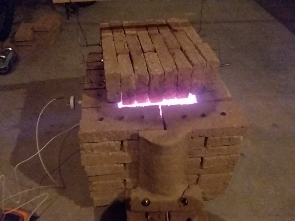
The final picture below shows the situation AFTER FIRING. Everything worked great - it was pretty cool to see the woven tube heat up to glowing orange - and afterward the tube and everything was intact and fine. Except... the tubing SHRANK! This pulled the heater coils somewhat into the interior of the kiln.
I probably could have pre-shrunk some additional lengths of tubing and re-routed the heater, and then gone and done the same for the other three heaters. But at this point I decided that was really more of a hassle than perhaps just replacing a heater element every now and then. The target temperature of the kiln, at 1800 F (1000 C), isn't even that hot by kiln standards. And according to several sources, replacing heating elements in kilns is a fact of life: source 1, source 2, although there are things that can be done to extend the lifetime of the heating elements (keep them clean, fire them first on an empty kiln, vent harmful gases, keep elements properly supported).
The plan for now is to go back to using naked elements, keep them as clean as possible, and don't run the kiln over 1800 F. The last one is easy since I haven't even got the kiln up to that temperature yet!
![]()
-
Second Light
10/24/2017 at 14:53 • 0 commentsNow we're cooking! A second heater, with the same specs as the first, was added to the kiln. This heater is powered from a separate 110AC circuit - a trip to the fuse box is necessary to figure out which outlets are a safe combination to use. Now the kiln gets nice and hot:
![]()
Just how hot does it get?
![]()
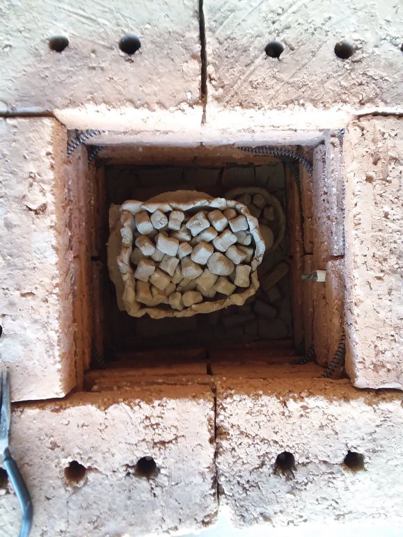
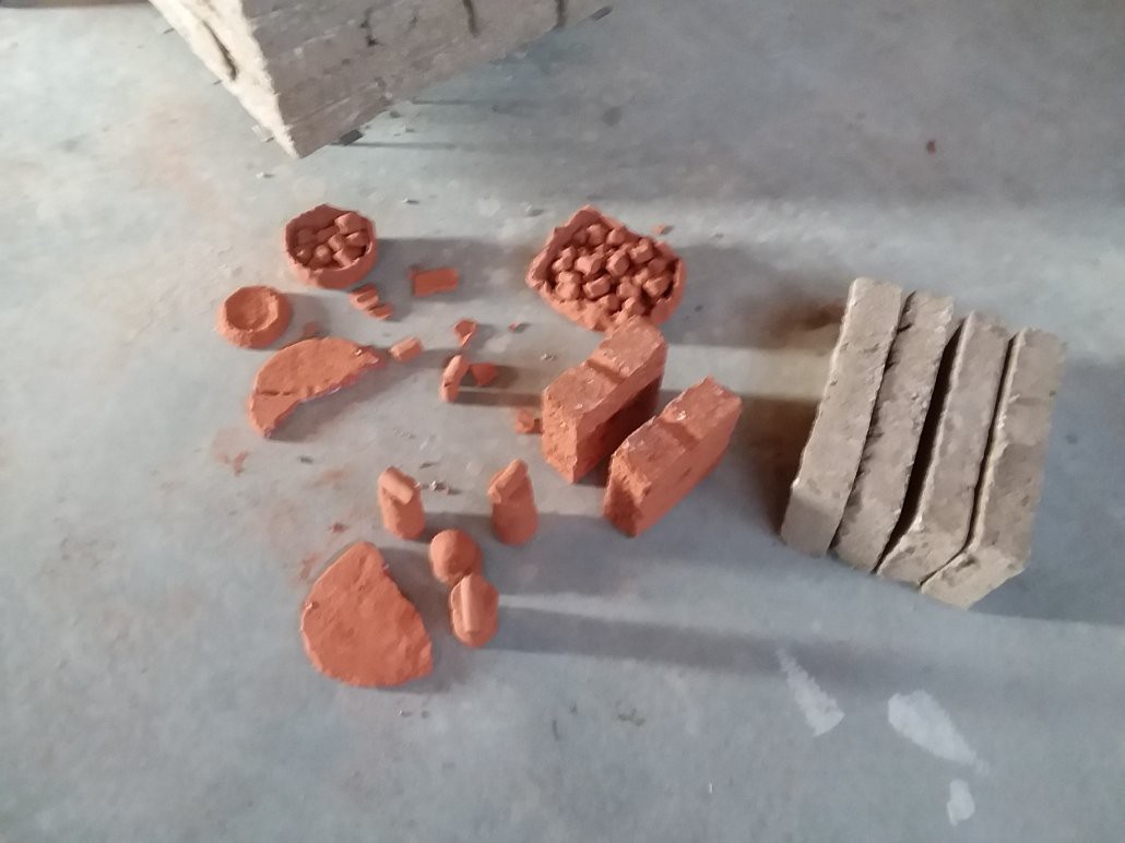
The highest recorded temperature was 1586 F (863 C or 1136 K). That's more than enough to melt aluminum, and it's at the low end of the acceptable range for firing clay. For this run, the kiln was loaded with a variety of trinkets we had made with some of the extra clay:
![]() After firing, the clay objects turned a deep red. The red color apparently indicates a high iron content in the clay, which according to some of the readers, can cause problems for the nichrome heater wire. So I may need to think about ways to insulate the nichrome from the bricks for long term use...
After firing, the clay objects turned a deep red. The red color apparently indicates a high iron content in the clay, which according to some of the readers, can cause problems for the nichrome heater wire. So I may need to think about ways to insulate the nichrome from the bricks for long term use...![]() As an aside, the extra heater wiring was installed with the help of some clay bead insulators:
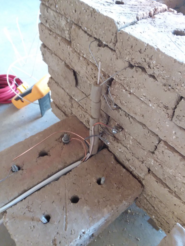
As an aside, the extra heater wiring was installed with the help of some clay bead insulators:![]()
-
Refining the Model
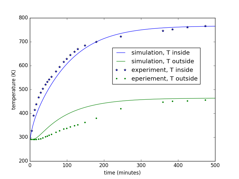
10/20/2017 at 04:41 • 0 commentsAfter the kiln's first run, it was found that it wasn't getting near as hot as I had hoped - not near as hot as the optimistic model had predicted either! In this log, we tweak the model parameters so that the time-dependent thermal model outputs a curve that is (somewhat) close to the experimental data from the kiln's first run. The script used for this is kiln_model_mathcing.py.
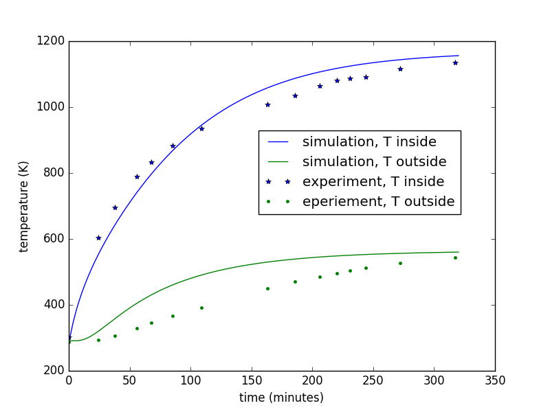
Here's the end result in graphical format:
![]()
The important model parameters are the following:
rho = 2000.0 # density of wall material in kg / m^3
k = 1.3 # thermal conductivity of wall material in W / (m*K)
c = 400.0 # specific heat capacity in J / (kg*K)
h = 12.0 # convective heat transfer coefficient in W / (m^2 * K)
Q_dot_in = 1500.0 # heater power in watts
T_inf = 291.0 # ambient temperature in Kelvin
A couple things to note...
- These values are arrived at manually - I tweaked 'em around until the graphs looked about right.
- The simulated inside temperature matches the data OK, but the simulation of the outside temperature has it heating up much faster than the experimental data showed. I'm not sure why.
- The value of k is much higher than I had initially guessed. This might be due in part to the large gaps between bricks. Sealing the gaps might improve (reduce) this value.
- The values of h and c are somewhat lower than I had initially guessed.
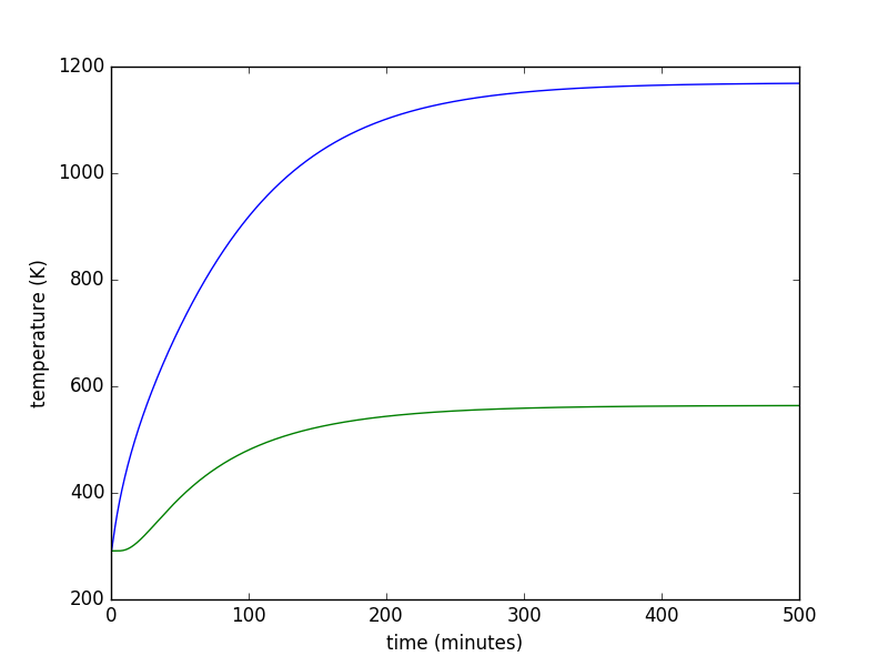
So how hot will this thing get if we add a second heater? Here are the traces using the above parameters for a heater of Q_dot = 3000 watts:
![]()
This gets up to about 1160 Kelvin, or 1628 degrees F, or 887 degrees C. Still not quite as high as I had wanted, but let's try it and see how high we get!
-
First Light
10/16/2017 at 09:34 • 2 commentsI always thought it was kind of cool how astronomers said that a new telescope saw First Light the first time it was used. I was thinking about calling this log entry "first heat" but just to be safe I googled that term before using it, and well, you can look it up yourself if you're interested in what it means. Anyway! Light is a kind of heat and today is the first time we turned the heater on, so First Light it is!
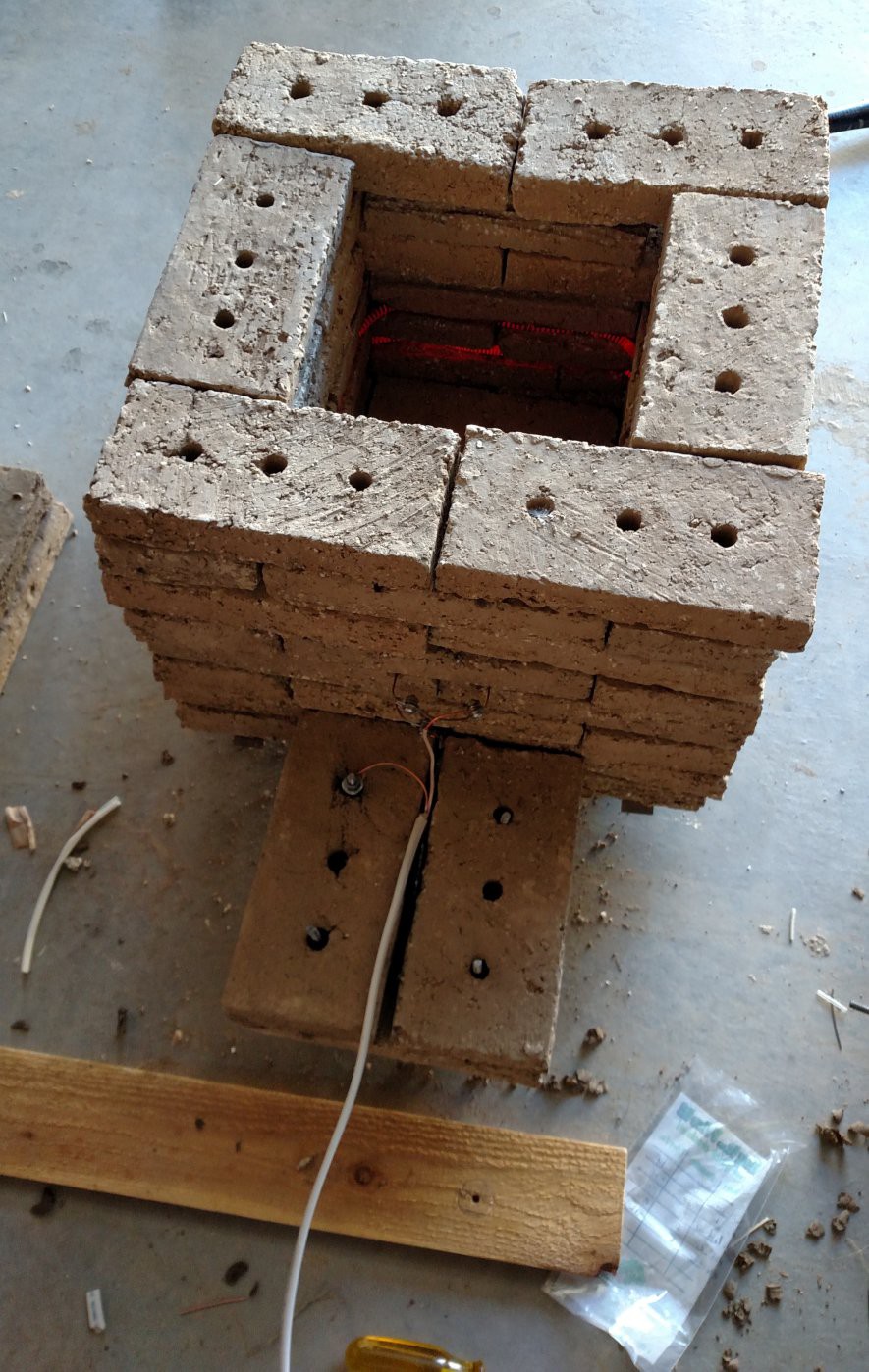
The good news is that the heater works and everything holds together and doesn't catch fire:
![]()
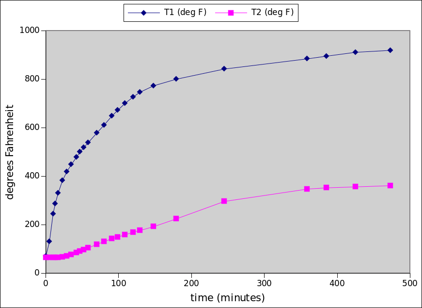
The bad news is that the kiln doesn't get as hot as it should:
![]()
In the plot above, T1 is the inside temperature and T2 is the outside wall temperature.
The next steps to improve this are:
- Adjust the parameters in the python thermal model so it matches the experimental data
- Decide if adding a second heater set will meet requirements, and if yes then add 2nd heater
- Seal up cracks and gaps between bricks with clay
- Try again!
The rest of this log shows the steps taken for final assembly of the kiln before testing.
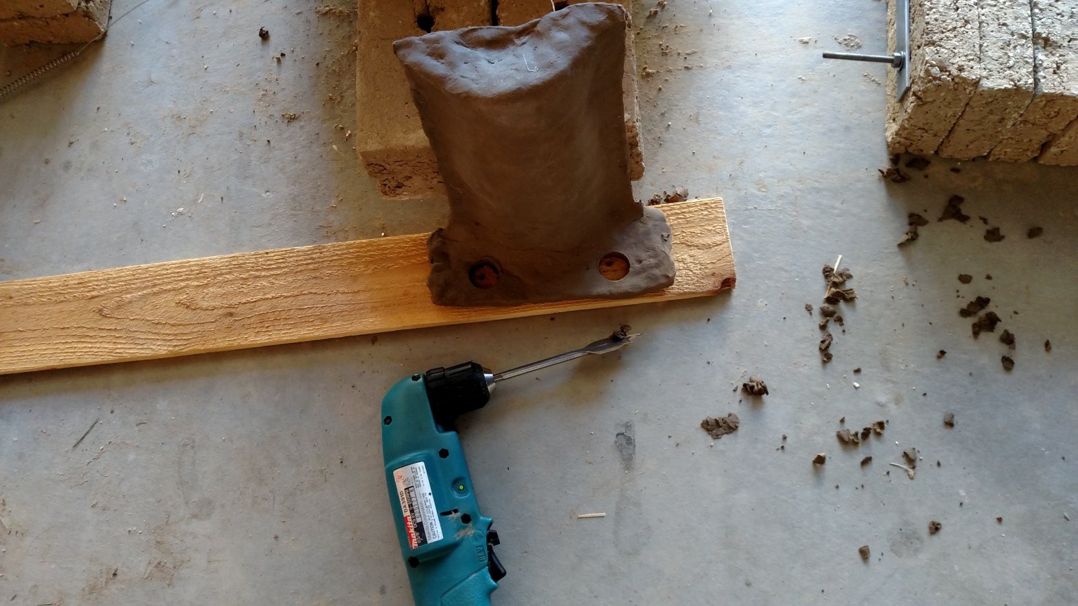
When it was time for assembly, the wiring cover had dried to leather hard. It worked pretty well to use a spade bit to cut clearance holes for the threaded rods in the base of the cover.
![]()
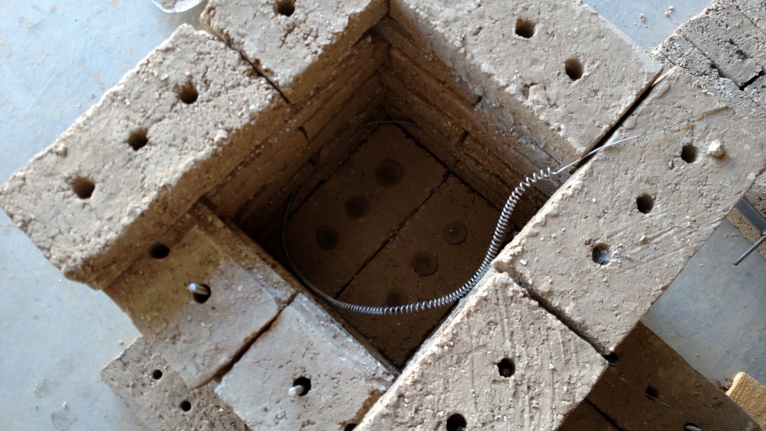
The heater coils fit fairly well into their slots in the bricks.
![]()
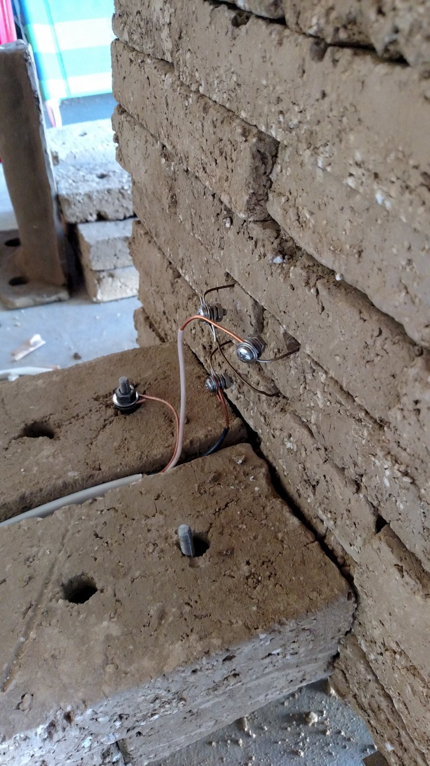
The nichrome heater wires were connected directly to standard solid household 12/3 wire (you can get this at hardware store like Home Depot, etc). The "conncector" is a stainless steel 8-32 screw and nut, with a stack of two #8 flat washers, two #10 flat washers, plus a #8 lock washer. After running for more than six hours, the plastic insulation on the copper wire was still intact, so apparently ambient cooling is OK to keep the copper side cold enough... for now.
![]()
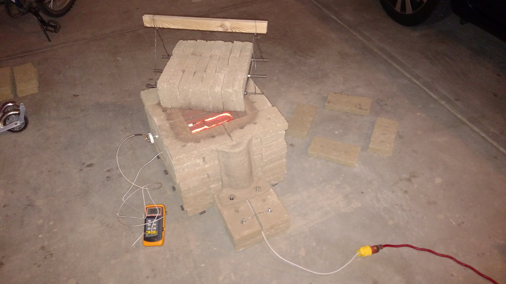
First Light!
![]()
This is a K-type thermocouple from Amazon, made by MN Measurement Instruments. It is designed for kilns. It fits into a groove that was cut in the brick by using a spare chunk of 1/4-20 threaded rod as an improvised file.
![]()
Here is the whole setup. The lid has a handle made of 1X2 and steel wire. A 2-channel thermocouple reader is connected to the internal thermocouple, and also to a small thermocouple which is embedded just inside the outside surface of the wall. The outer thermocouple was installed by drilling a small hole to a depth of about 3/8 inch (1 cm) and stuffing the thermocouple inside.
The thermocouple reader is a cheap off-brand meter that I got off Amazon in a hurry. There seem to be about half dozen different variants of these on Amazon, and a lot of the reviewers have terrible terrible things to say about them. In my experience it is indeed cheaply made, and one of the two probes it came with failed on arrival. However, it seems to be fairly accurate with the two good probes I have and it was fast and cheap! In the future I might get a thermocouple interface chip from Digikey and make a little Arduino interface for data logging.
![]()
-
Winding the Heater Coils
10/16/2017 at 05:46 • 0 commentsAs described in this earlier project log, the initial design has two heater elements, each 4 ohms, in series, for a total heater resistance of 8 ohms.
Each heater will be made of 5 meters (16ft) of 16AWG Nichrome 80 wire. Each heater will be wound in 250 turns on a 3/16 inch diameter mandrel, with a pitch of 3.4mm (0.134 inches), for a coil length of about 33 inches (84 cm).
The kiln brick assembly contains slots for an additional pair of heater coils if they are needed. These would need to be powered from a separate 110 VAC circuit to avoid blowing the 15 amp circuit breaker.
At first, I was planning to wind the nichrome wire using my little Sherline lathe. I got the idea for this from this video: How to Wind a Coil Spring on the Metal Lathe. This would have involved disassembling the tailstock so the mandrel could pass through it, along with the construction of various jigs and fixtures. It probably would have worked but it would have been tedious.
But then I found these two videos:
How to make a Heating Element Coil Winding Machine
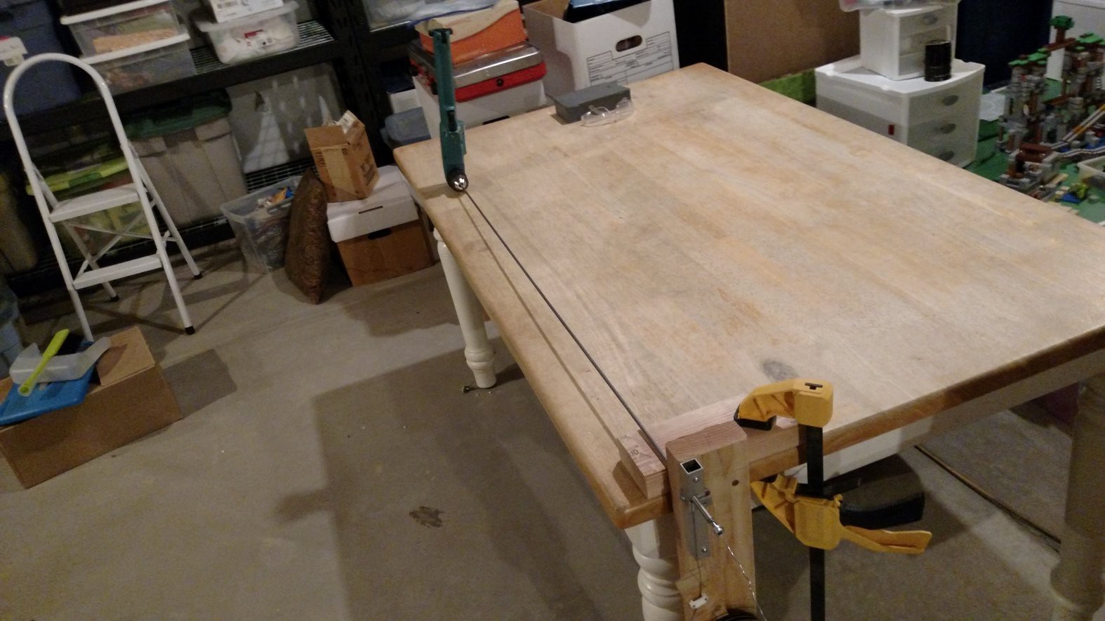
The special-purpose coil-winding machines described in these videos are so cool I decided I had to build one myself. I'm very pleased to say that I was able to construct a working coil winder exclusively with stuff I had sitting around. Here's a video of it:
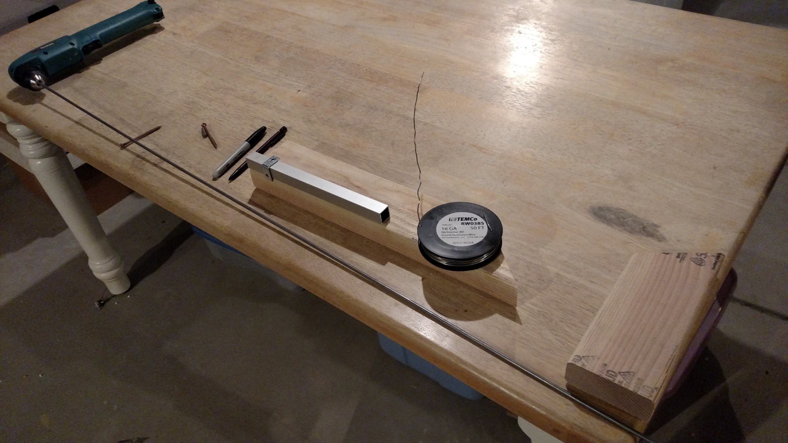
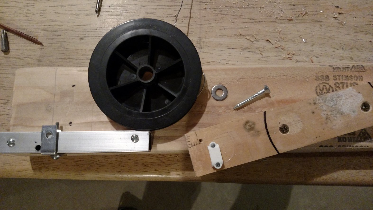
This is the pile of parts I started with:![]()
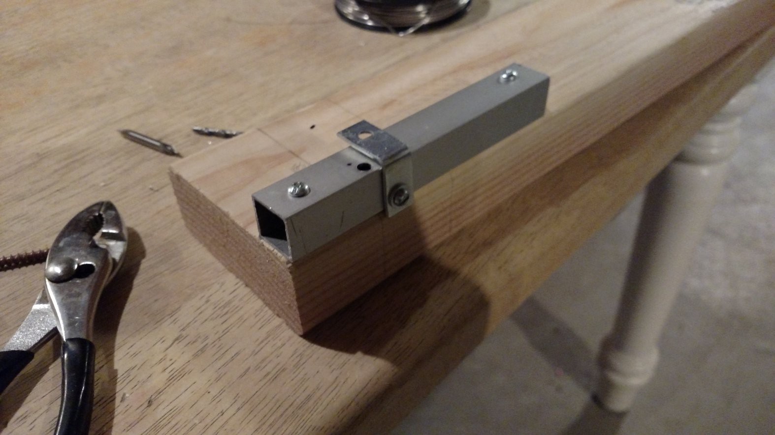
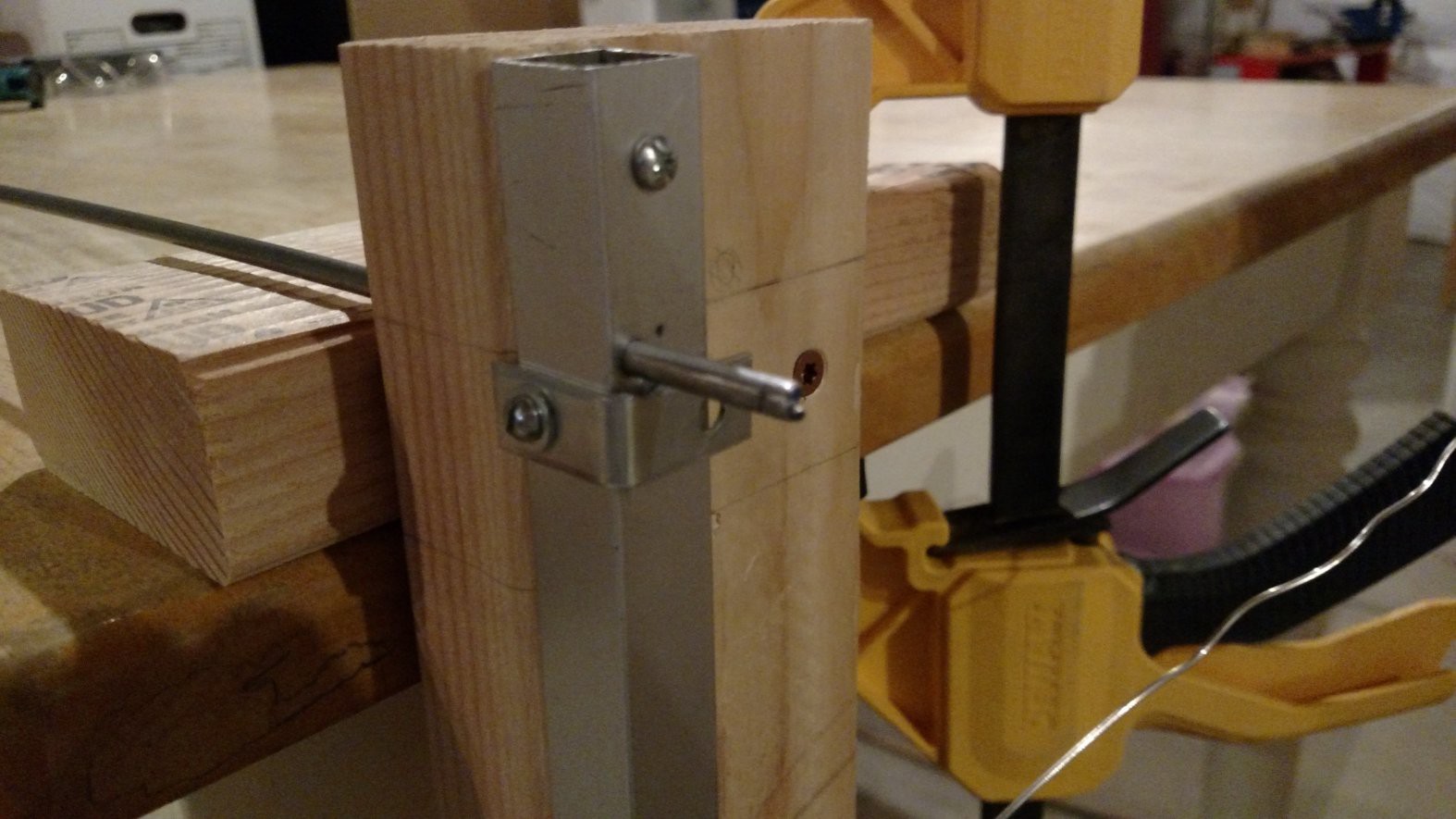
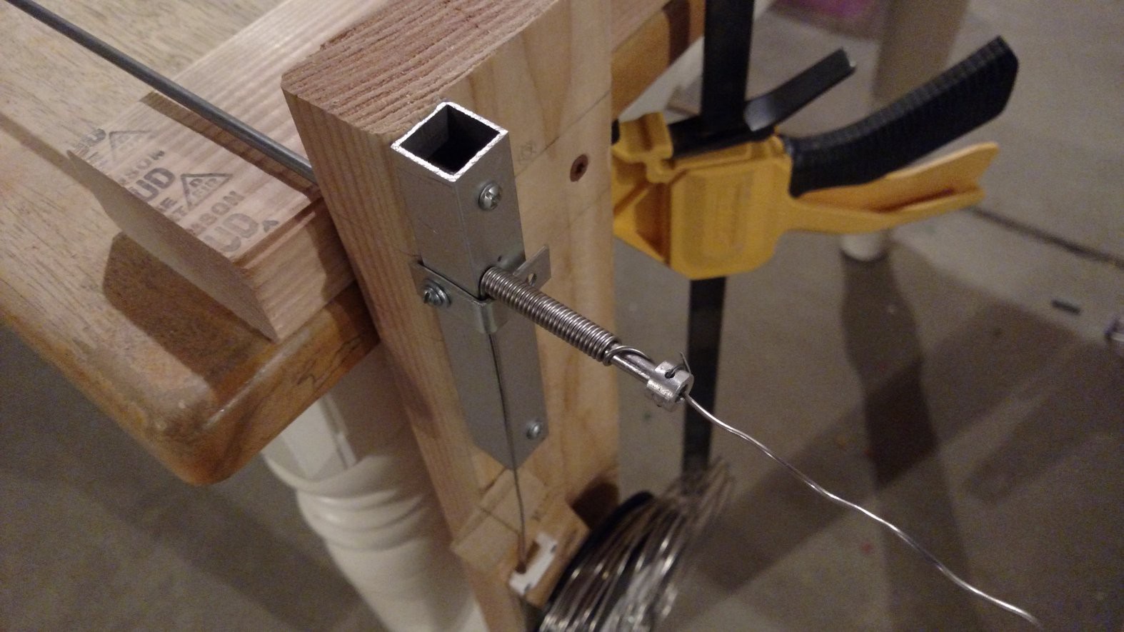
The square aluminum tube is screwed onto the 2X4. A 3/16 hole through tube and 2X4 guides the 3/16 steel rod mandrel. The small L-bracket is carefully spaced about 1/16 inch away from the surface of the tube. This is for guiding the wire.
![]()
The chunk of wood on the left is added to space up the spool. Note the white cable mount (center) used as a wire guide.
![]()
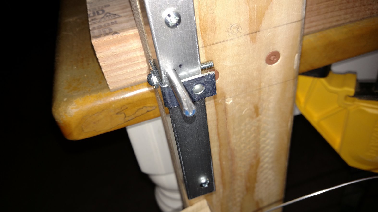
Using a file and a hacksaw, a slot is cut lengthwise in the end of the mandrel. This slot holds the wire during winding.
![]()
It is hard to see in this image, but on the opposite side of the lengthwise slot (see above) there is a cross-wise slot in the mandrel. This is for wiring on the bushing that clamps the wire in place. Note the semi-circular clearance cut that has been filed in the L-bracket, directly underneath the mandrel.
![]()
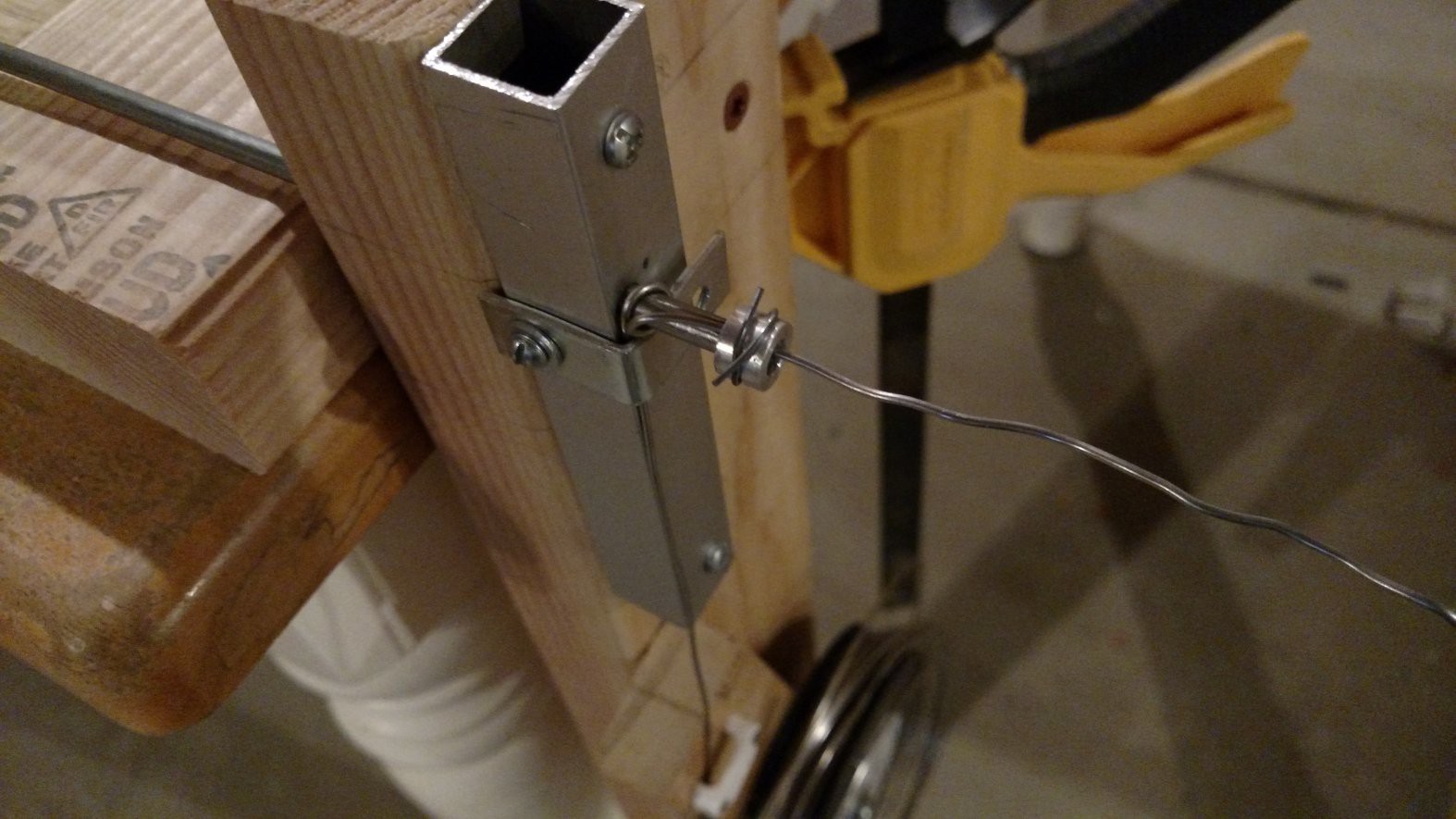
This shows a closeup of the wire clamped to the mandrel with a small bushing, which has been wired onto the end of the mandrel through the cross-wise slot. Note the spool mounted below. (It turns out the wire was wound too loose on the spool for good feeding, so the spool in its entirety had to be removed and the wire fed loose by hand.)
![]()
Drill connected to mandrel and everything set up for winding. Protip: do not knock the drill off the table - it will bend the mandrel. Don't ask me how I know that...
![]()
It works! Except for the spool... The spool was removed and the wire loosely fed in by hand by an assistant.
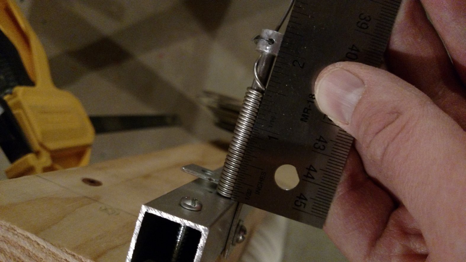
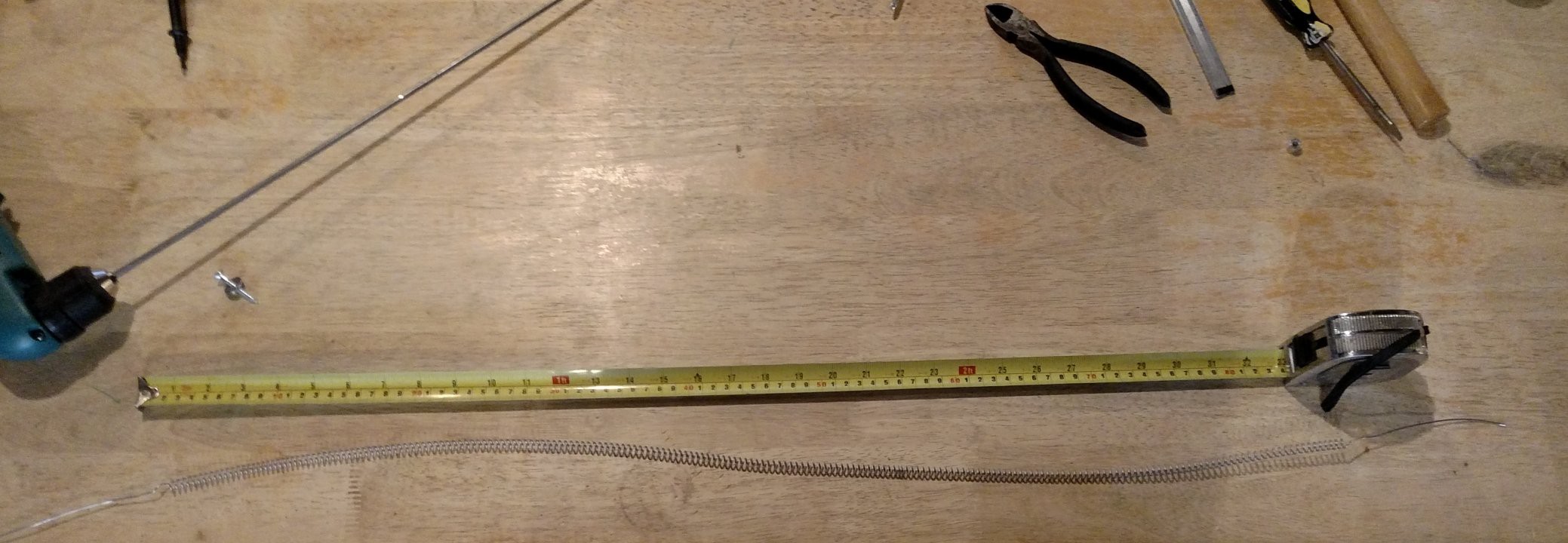
![]() There are about 20 turns per inch, so we need to wind 250/20 = 12.5 inches of tightly wound coil. This will then get stretched out for the final installation in the kiln.
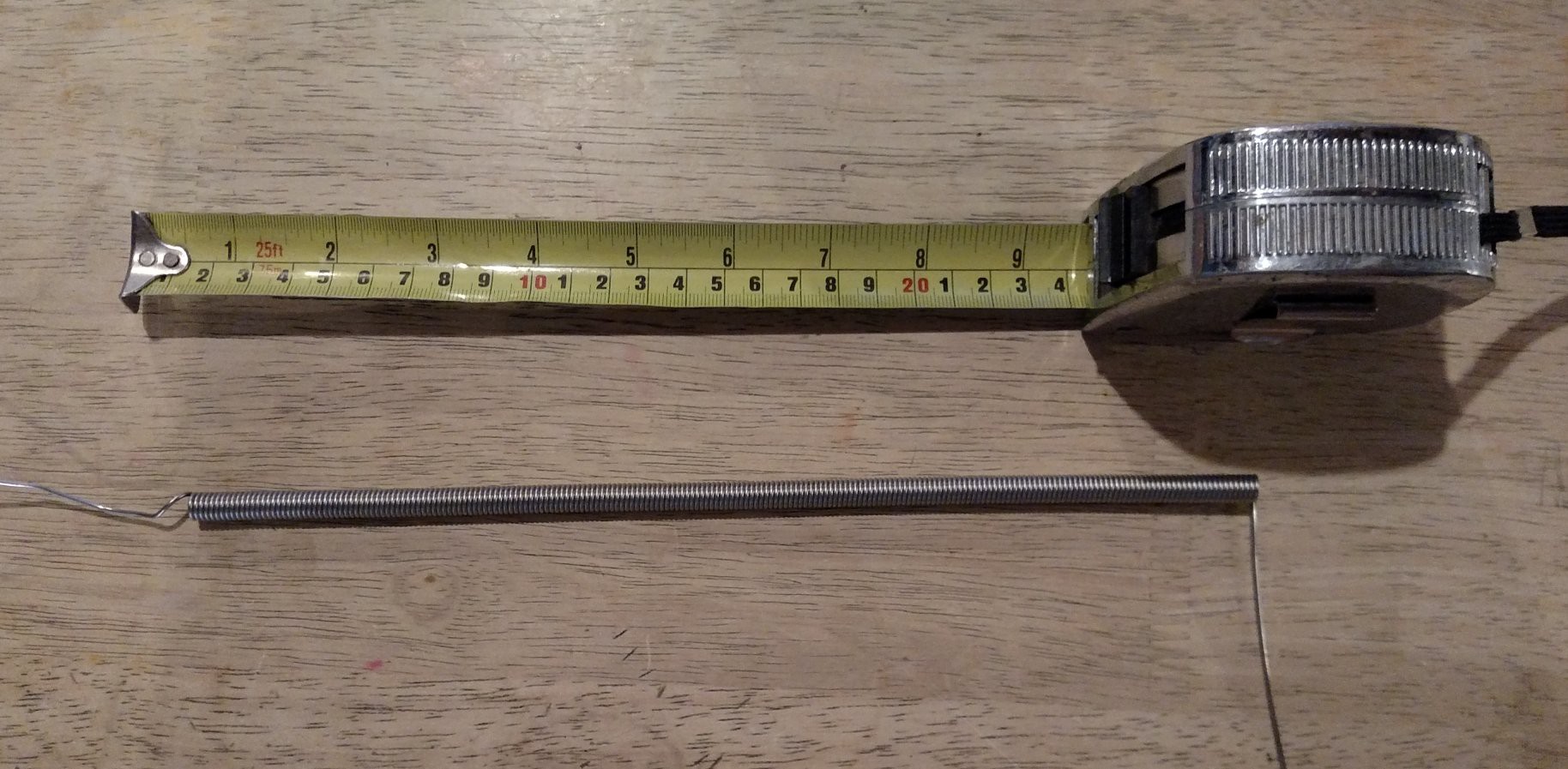
There are about 20 turns per inch, so we need to wind 250/20 = 12.5 inches of tightly wound coil. This will then get stretched out for the final installation in the kiln.![]() The first coil was a little longer than 12.5, so the second coil turned out a little shorter:
The first coil was a little longer than 12.5, so the second coil turned out a little shorter:![]() It's easiest to stretch out the coil by clamping one end in a vice and then (carefully) pulling the other end slowly and steadily with pair of pliers.
It's easiest to stretch out the coil by clamping one end in a vice and then (carefully) pulling the other end slowly and steadily with pair of pliers.![]()
-
Wiring Cover
10/15/2017 at 08:01 • 0 commentsThe initial kiln is going to have two four-ohm heater coils connected in series. This eight-ohm heater will be connected to 110 VAC mains electricity on a 15 amp circuit. There are slots to add another pair of heater coils if needed, but these would need to be powered by a separate circuit.
The heater wires poke out the side of the kiln, and the plan is to just connect them to the supply wires with nuts and bolts. This hodge podge needs a safety cover so that no one accidentally comes into contact with mains electricity. (Yes the coils on the inside of the kiln will be exposed, but the plan is that the kiln will be turned off before opening.)
This log shows how a prototype wiring cover was made from clay. If this really works well then I'll just use this cover. If it kinda works well, I may try making an improved cover. If it doesn't work well then I'll try something different.
This idea of using clay to make structure and/or mechanical parts certainly isn't a new thing. However, for me it was inspired recently by watching the kind of machines that Primitive Technology Guy can make out clay with his bare hands.
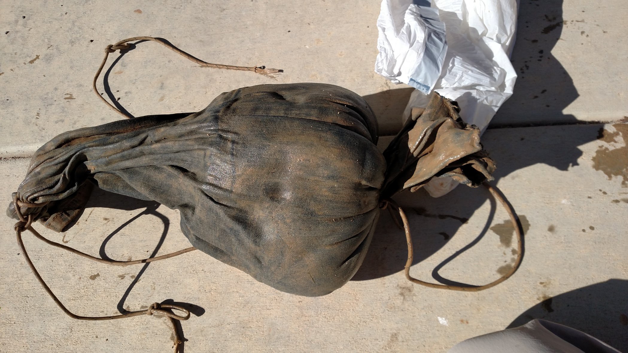
This is the clay we started with. It had been stored for a few weeks in a tied-off chunk of blue jeans leg, inside a plastic garbage bag. Kind of gross but this kept it workable.
![]()
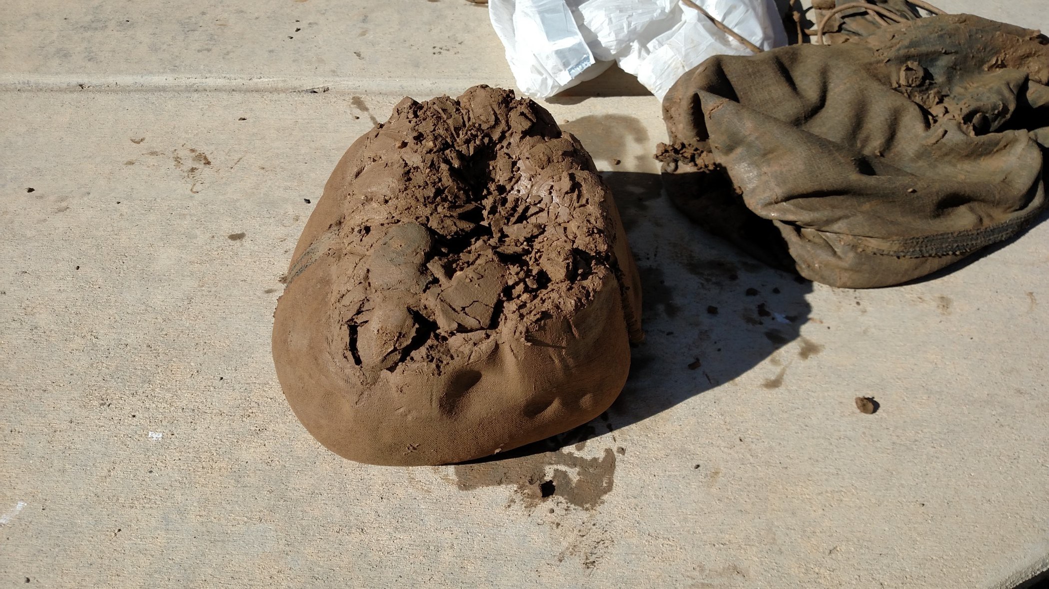
This is what the clay blob inside looked like.
![]()
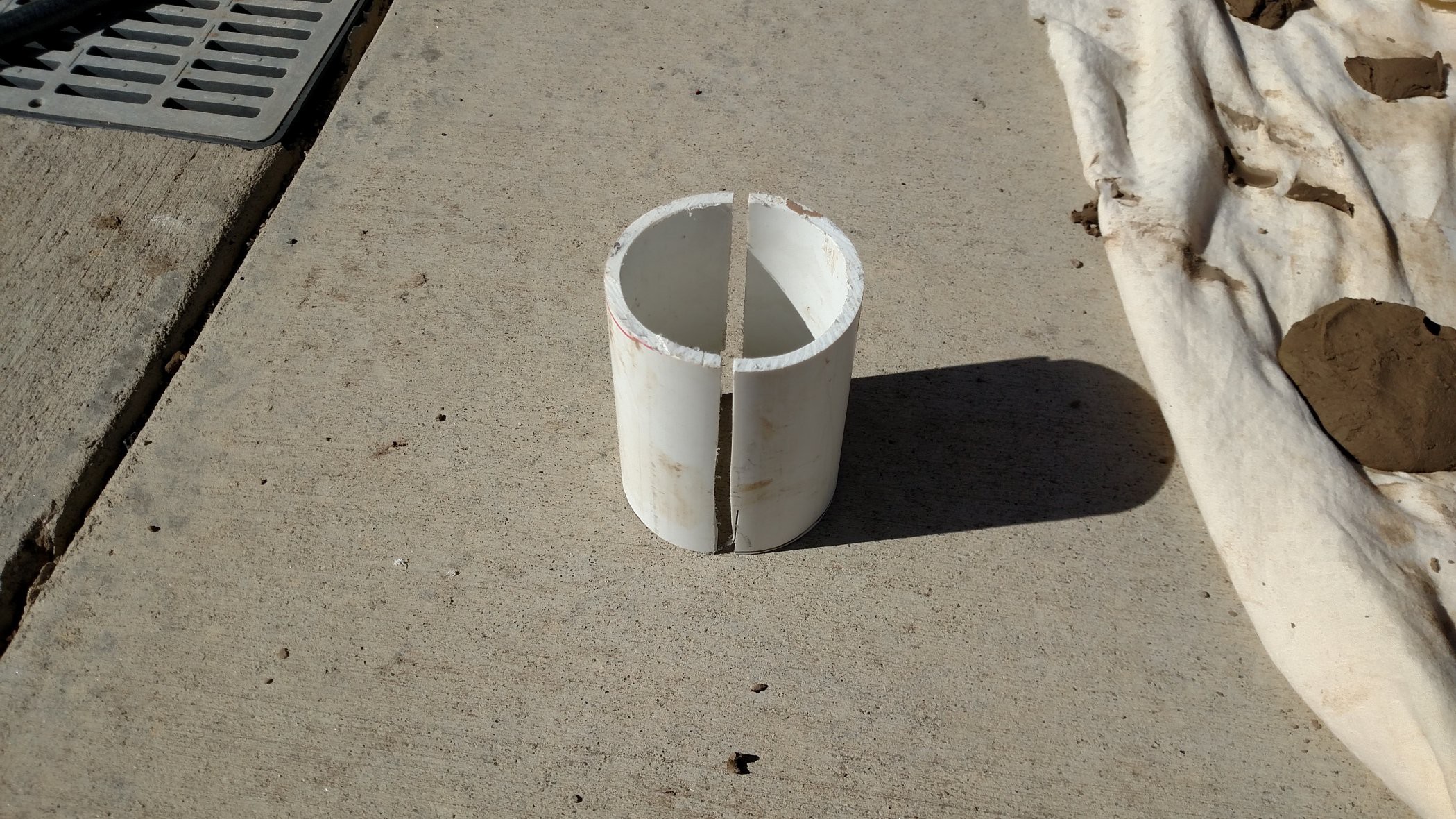
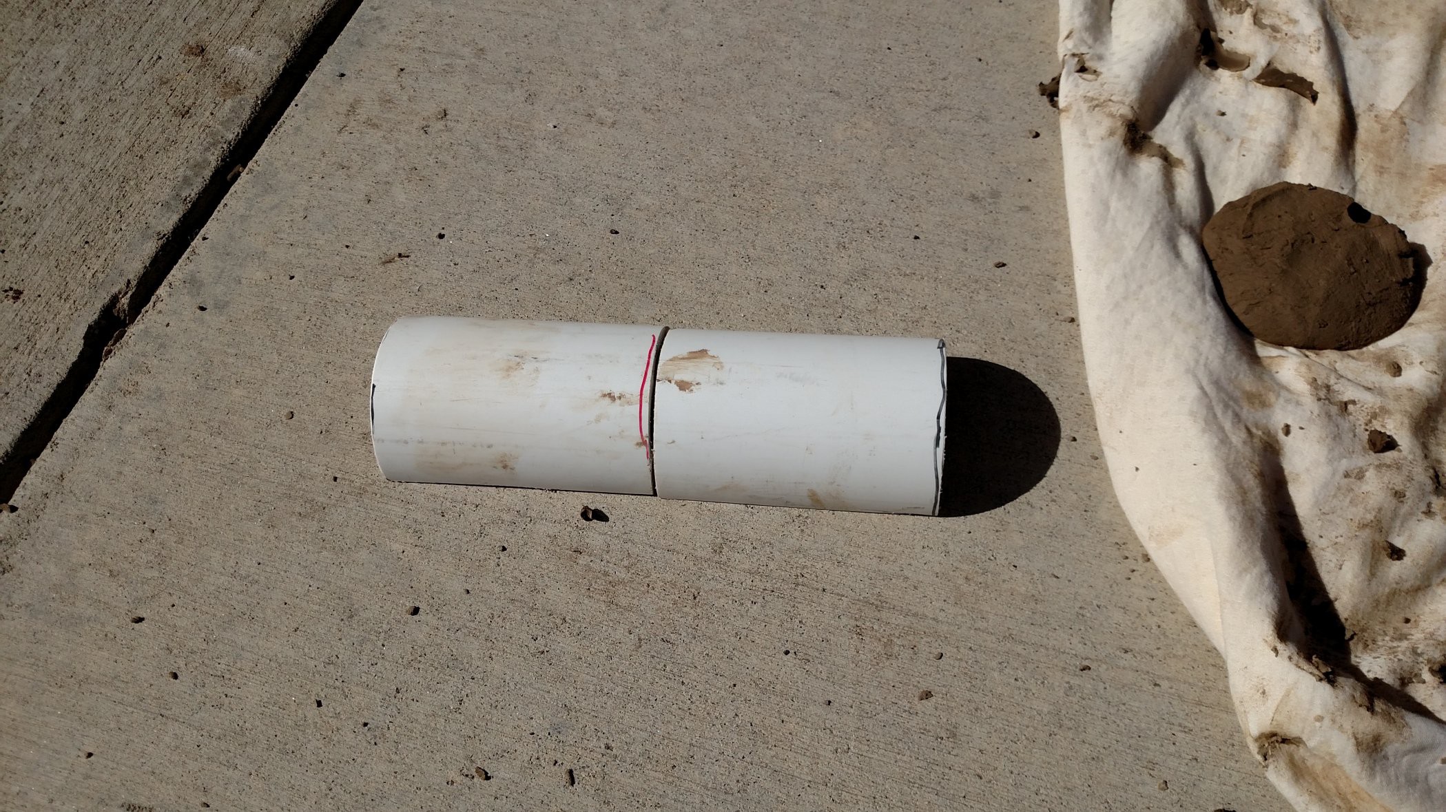
A chunk of PVC pipe was used to make a form for the clay cover.
![]()
![]()
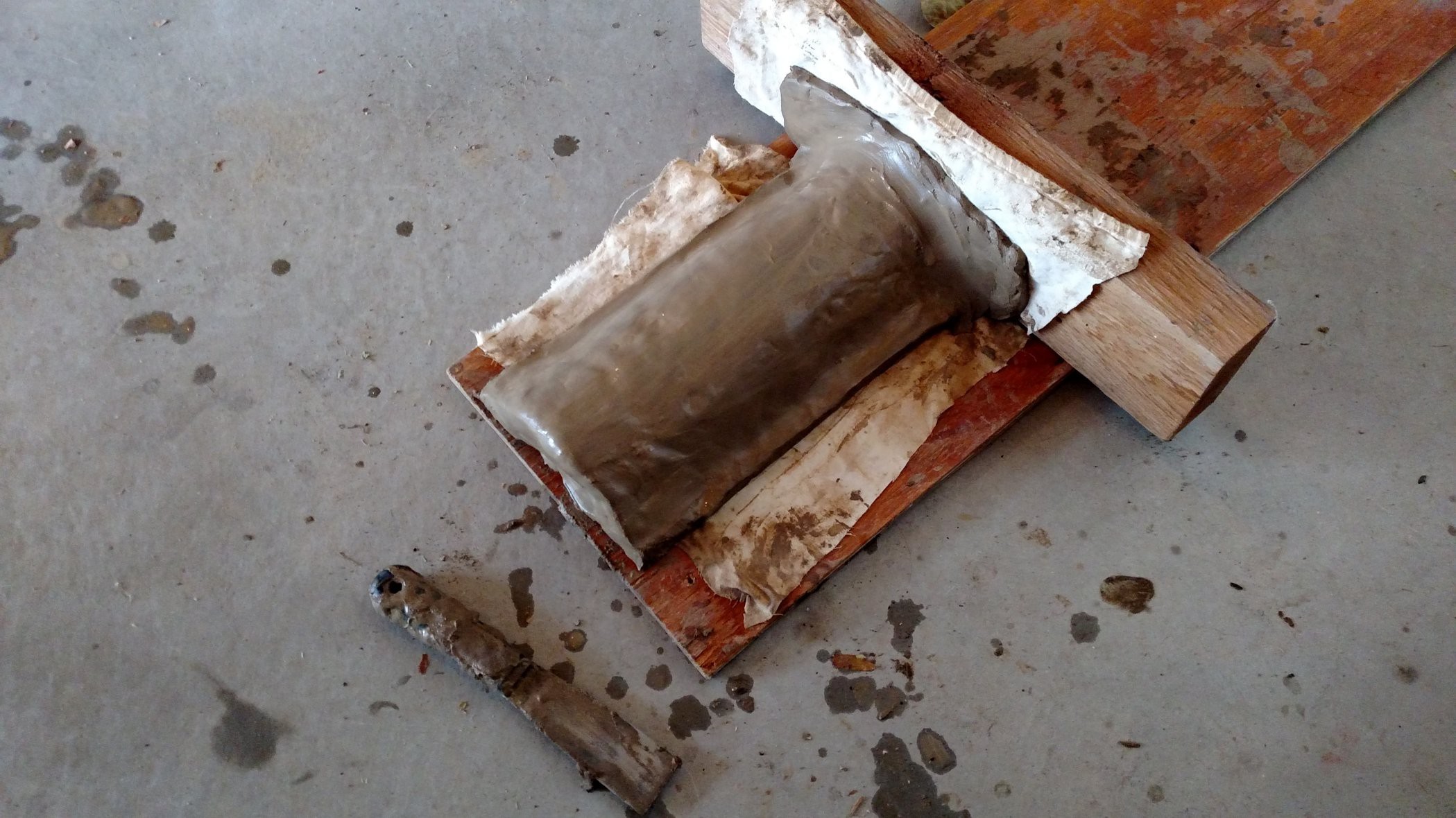
The PVC pipe form is set on a piece of cloth on top of a board. Another piece of cloth is draped over the form. All this cloth is needed so the clay doesn't stick to the form and crack as it shrinks and dries. The clay is molded over the form by hand to make the cover.
![]()
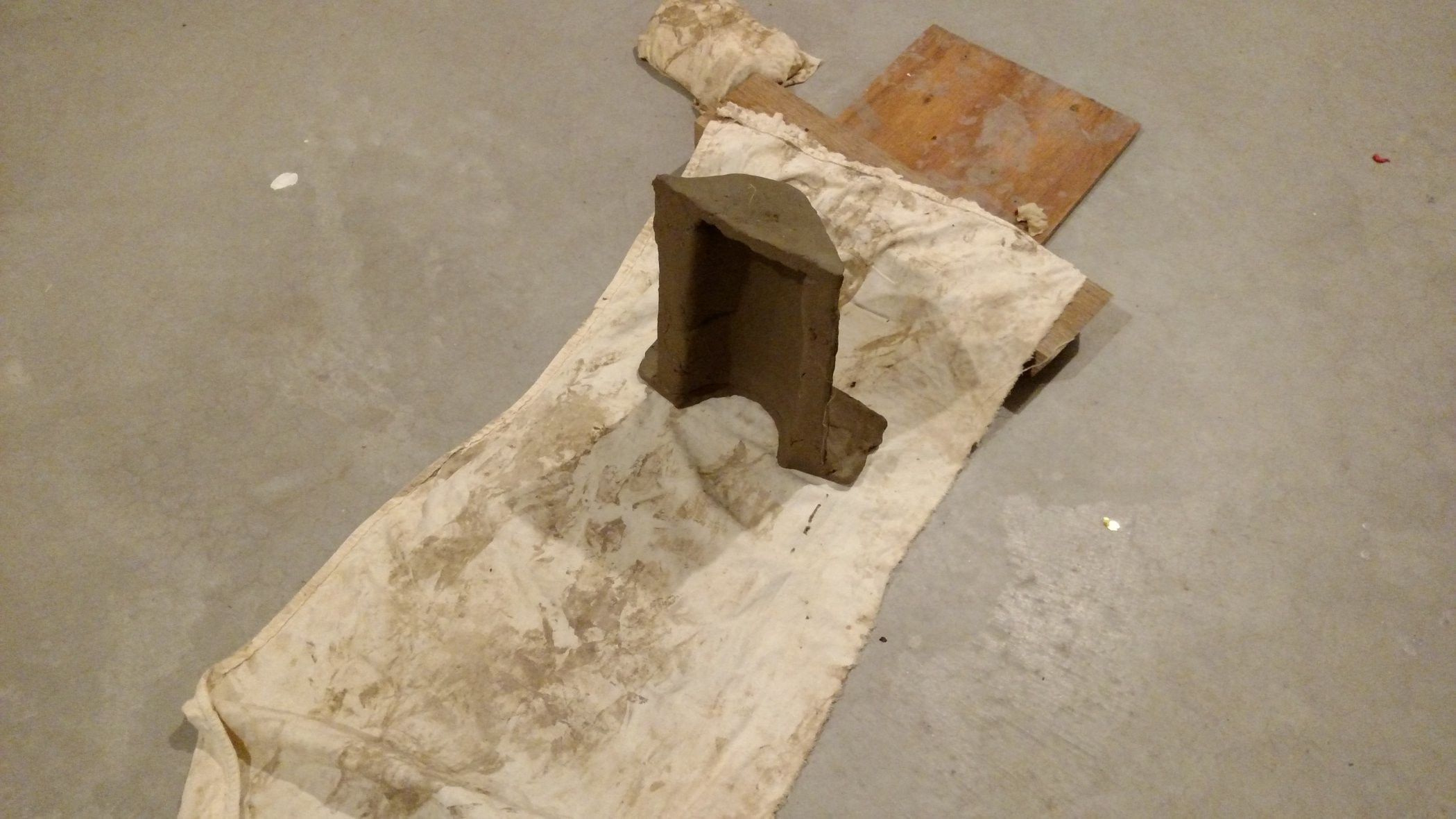
After drying for a few hours, the cover is rigid enough to stand on its own. Tomorrow it gets added to the kiln! Well, later today to be exact. We're coming up on the prize deadline ;-)
![]()
-
Kiln Assembly
10/09/2017 at 07:18 • 0 commentsThis log covers a mechanical fitup test of the bricks and hardware for the main body of the kiln. The heater coils and a wiring cover are still needed - they should appear soon in a later update.
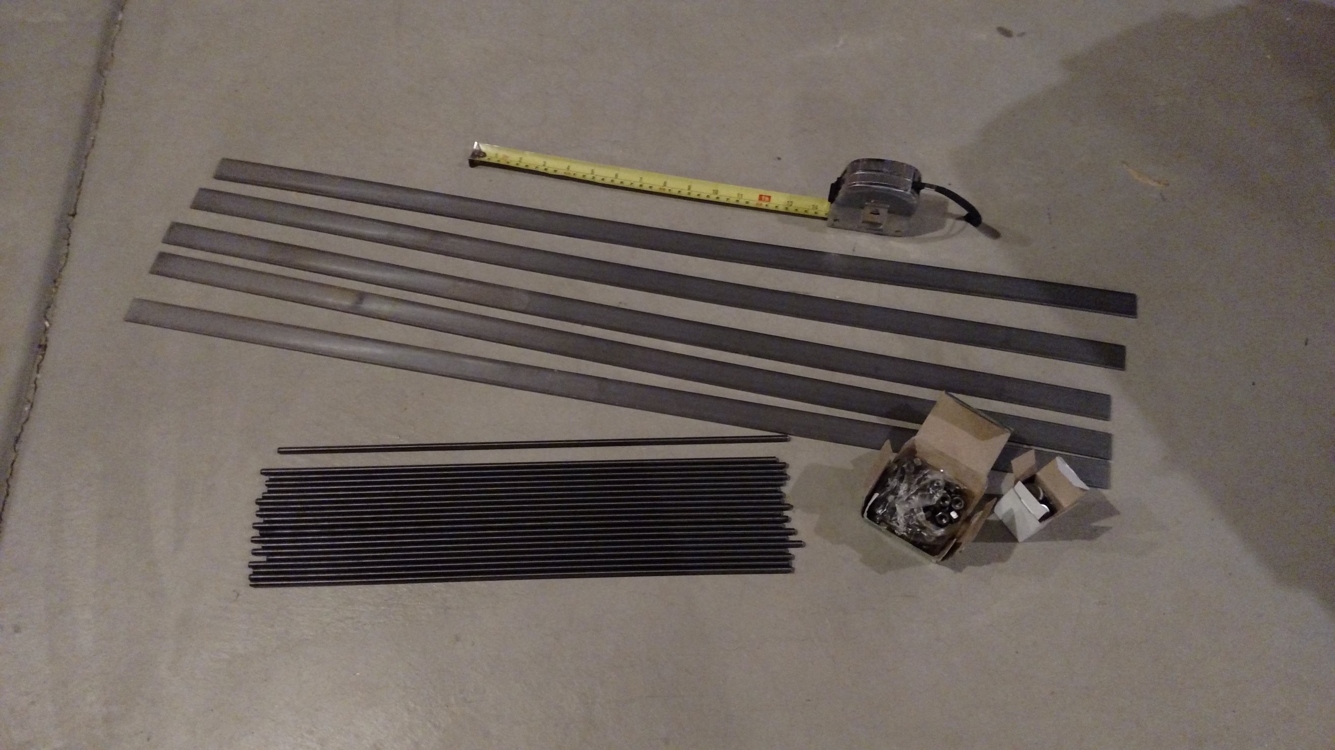
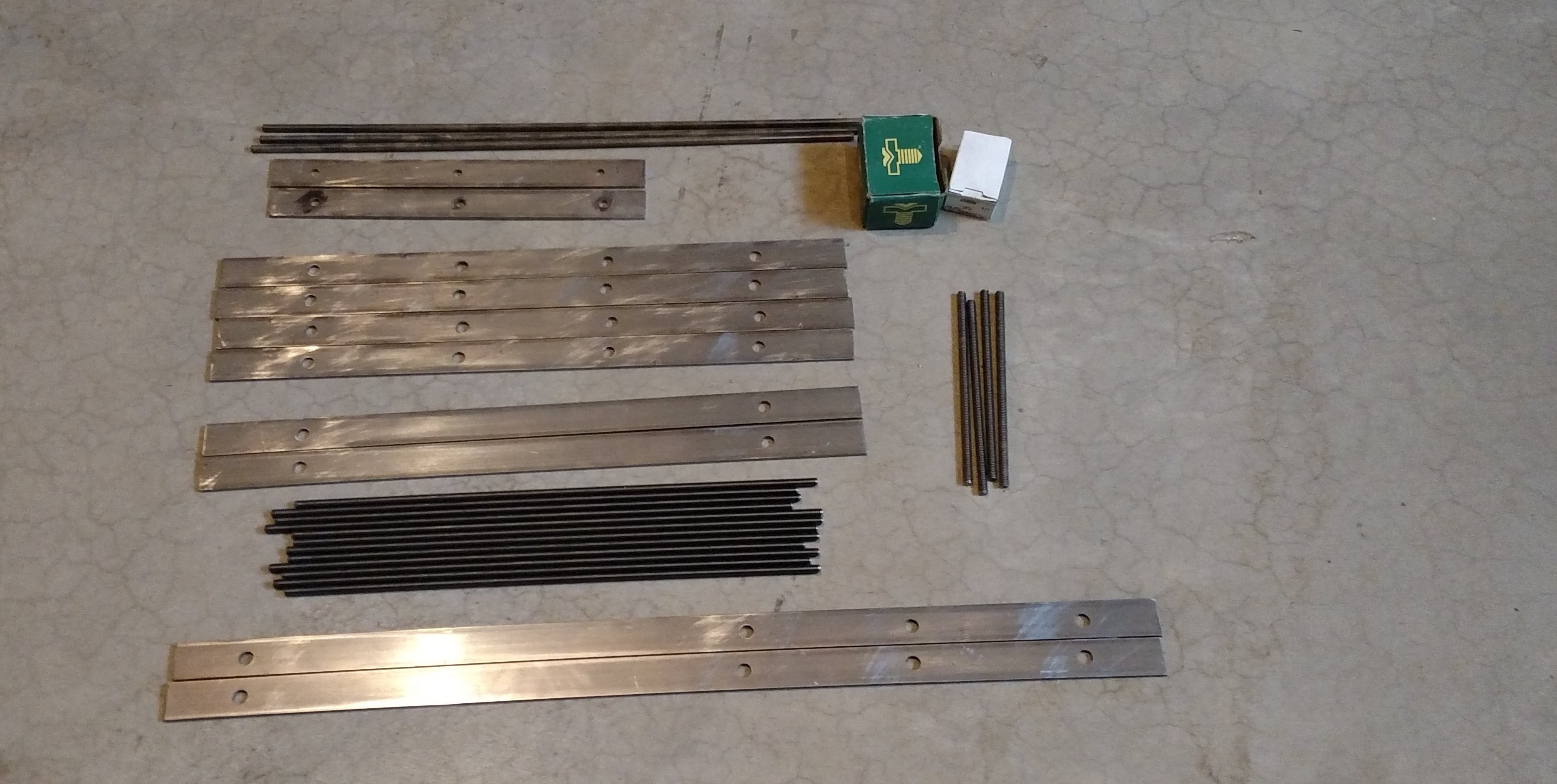
The image below shows the metal parts out of the box from McMaster
![]()
Metal parts out of the box
I used a hacksaw and vice to cut the strips and rod to length, and a hand drill to drill the holes. The hole drilling was pretty tedious. If anyone else is thinking about this reproducing this design, consider obtaining a drill press, or finding a way to use metal strip that comes pre-drilled (Unistrut, for example).
![]()
Metal parts after cutting and drilling
The OpenSCAD file kiln-assembly-V1.scad will calculate and then echo out the lengths and hole locations for each of the strips. This output is pasted below for reference. The hole diameter for the short and long strips is 17/64 inch, which is quite oversize for the 1/4"-20 threaded rod. A sloppy fit was desired/required because the bricks are not made to very close tolerances. Furthermore, it is expected that when the kiln heats up, things are going to change size and move around. It will be better for things to be a bit loose so they move, rather than have everything clamped down and then start cracking bricks everywhere...
ECHO: "lid strip dimensions in INCHES"
ECHO: "lid strip length =", 11
ECHO: "hole one location from end =", 1.25
ECHO: "hole two location from end =", 5.5
ECHO: "hole three location from end =", 9.75
ECHO: "short strip dimensions in INCHES"
ECHO: "short strip length =", 18
ECHO: "hole one location from end =", 2.625
ECHO: "hole two location from end =", 6.875
ECHO: "hole three location from end =", 11.125
ECHO: "hole four location from end =", 15.375
ECHO: "long strip dimensions in INCHES"
ECHO: "long strip length =", 25
ECHO: "hole one location from end =", 1.875
ECHO: "hole two location from end =", 6.125
ECHO: "hole three location from end =", 10.375
ECHO: "hole four location from end =", 14.625
ECHO: "hole five location from end =", 18.875
ECHO: "hole six location from end =", 23.125
Hole two and hole three of the long strip can be omitted. And hole two and hole three of two of the six short strips can be omitted. View in OpenSCAD to get a clearer picture of how the parts go together, or check out the build instructions page.
OK now we're ready to get started! This image shows the metal parts set out and the threaded rods threaded into nuts and washers:
![]() Getting started...
Getting started...Next up the rods and strips and kind of sort of assembled. This is a real spaghetti mess. I can hear everyone asking at once: "Why don't you put nuts on the top side and tighten that thing down?!??!??"
Because I want it to be loose so the bricks will all shake down in place as I add them. And also so things can move around when the kiln heats up.![]() A real spaghetti mess
A real spaghetti mess![]()
Brick layer one
![]()
Brick layer two
![]()
Brick layer three
![]() Brick layer four
Brick layer four![]()
Brick layer five
![]()
Brick layer six
![]()
Brick layer seven
![]()
Brick layer eight
![]() Lid
Lid![]() Fitupt Test Complete!
Fitupt Test Complete! -
Heater Specification
08/26/2017 at 16:40 • 0 commentsThe kiln has two heating elements, each about 33 inches (84 cm) long - this is determined by the physical construction of the kiln. We are looking for a heater power of 1500W at about 110AC, so this gives us a heater resistance of about 8 ohms and heater current of about 13.6 amps. The resistance of the heater will increase slightly as it heats up, but for sizing purposes we'll use the cold resistance so we don't trip the (15 amp) breaker when the kiln starts up. There are two options: two 16 ohm heater elements in parallel, or two 4 ohm heater elements in series.
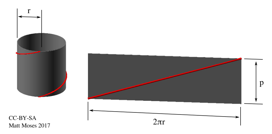
It is likely that the heater will be wound into a coil, so we need to know how to calculate the length of a helical path. Referring to the figure below, we have the length of one turn of a helix as
where r is the helix radius and p is the pitch (distance traveled along axis for one turn). L_helix is the length of the red trace shown in the image below. The total length of the heater wire is
and the total length of the coil is
where N is the number of turns.
![]()
The next step is to size some candidate heater elements using parameters for some common nichrome heating wire. According to this table on the Wikipedia Nichrome page the recommended wire gauge for a 1500W heater operating at 110-120V is B&S No./AWG 12-16.
As an initial check, let's pick the Nichrome 80 alloy (this appears to be the same as "Nichrome V" in some sources). According to Wikipedia, this alloy has a composition of 80% nickel and 20% chromium, and a resistivity of 1.09E-06 ohm meters. With these numbers, a 16 ohm wire would be 19 meters (63 ft) long. That's a little long. A 4 ohm wire would be 4.8 meter (16 ft) long. So let's go with two 4 ohm heaters in series.
OK, on to the next step. Let's stick with 16AWG Nichrome 80 for the moment. We'll need about 5 meters of wire (16 ft) for each 4 ohm heater.
At this point, we have several constraints on the heater coil:
16AWG, Nichrome 80
L_coil = 0.84 m (33 inches)
L_wire = 5 m (197 inches)
r = 3mm (0.12 inches) - this is set by the desire to have a winding mandrel of 3/16 inch diameter
These constraints completely determine the shape of the coil, and we can solve the above equations for the pitch p. First let's write down this relation
and then we can plug this into the very first equation up top and rearrange to get
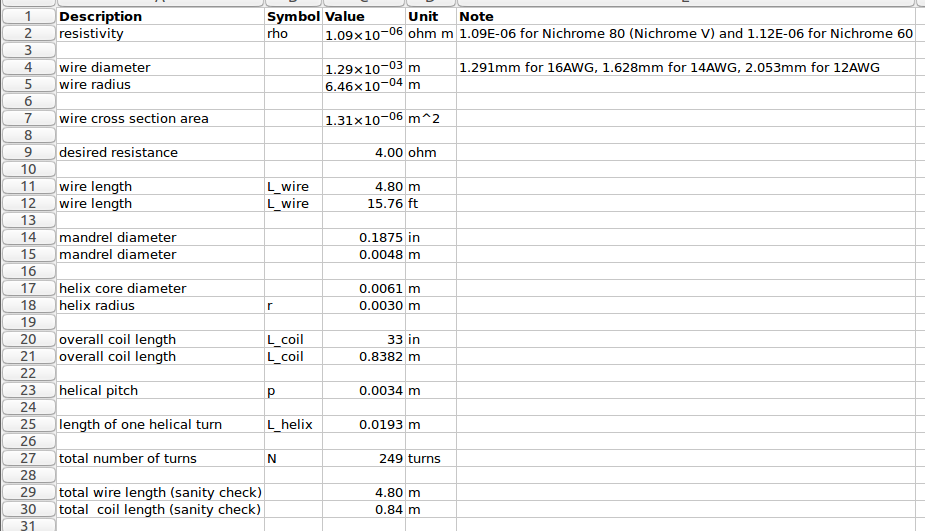
Finally! Now we can get the pitch of the coil and figure out if this is something we can wind by hand using the little Sherline lathe. There is a spreadsheet to perform these calculations on the Repkiln Github repo called heater_coil_calculations. Here is a screen capture,
![]() So the pitch is 3.4mm (0.134 inches). It should work out fine to wind this by hand on the lathe. Stay tuned for that in a later update!
So the pitch is 3.4mm (0.134 inches). It should work out fine to wind this by hand on the lathe. Stay tuned for that in a later update!SUMMARY: There will be two heater elements, each 4 ohms, in series, for a total heater resistance of 8 ohms. Each heater will be made of 5 meters (16ft) of 16AWG Nichrome 80 wire. Each heater will be wound in 250 turns on a 3/16 inch diameter mandrel, with a pitch of 3.4mm (0.134 inches), for a coil length of about 33 inches (84 cm).
-
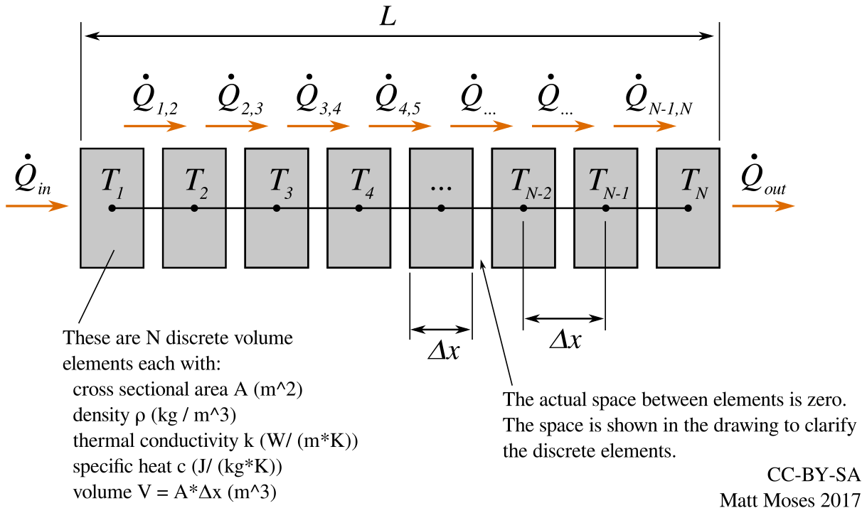
Numerically Solving the 1D Transient Heat Equation
08/19/2017 at 17:18 • 1 commentIn an earlier log we looked at the steady-state conditions to get an idea for how hot the inside of the kiln would get. This helped us get an idea for what thermal conductivity, wall thickness, and heater wattage were acceptable for getting the kiln to the desired temperature. But the steady state analysis does not tell us anything about the rate of heating. It is useful to have an estimate for how long will it take the kiln to warm up and cool down. In this project log we estimate this time-dependent behavior by numerically solving an approximate solution to the transient heat conduction equation.
As we did in the steady-state analysis, we use a 1D model - the entire kiln is considered to be just one chunk of "wall". We want to model the temperature of the wall material as we move from inside to outside.
Other assumptions: material properties are constant across x, t, and T. In other words: density, thermal conductivity, specific heat capacity are constant for the entire wall, for all time, for all temperatures.
![]()
The partial differential equation that describes heat flow in the wall is
where T is temperature, t is time, k is thermal conductivity, c is specific heat, rho is density, and x is distance through the wall, from inside the kiln to outside. We also need to specify the boundary conditions (heat flow at inside and outside surfaces) and the initial conditions (initial temperature profile of wall) in order to find a solution to this differential equation.
There are many ways to solve this equation analytically. However, we have kind of funny boundary conditions that make an analytical solution somewhat mathematically involved. An alternative way to solve this is to approximate the system as a finite difference equation, and then numerically integrate it using a simple python script.
The first step is to convert the partial differential equation into a recurrence relation with finite differences. The first derivative in time, evaluated at location x, becomes
The second derivative in space, evaluated at time t, becomes
Now we can plug these approximations into the original equation to get the recurrence relation that gives us an approximate solution
The above relation holds for the internal pieces of the wall, but not for the boundaries. At the inside surface of the wall, we need to look at the heat transfer from the heater. At the outside surface, we need to look at the convective and radiative heat transfer to the surroundings.
For the volume element on the inside boundary, where x = 0, we have
For the volume element on the outside boundary, where x = L, we have
where
and
where T_inf is the temperature of the surroundings, sigma is the Stefan-Boltzmann constant, and h is the convective heat transfer coefficient.
Now we have all we need to write a little script to iterate the recurrence relation. You can find a python script that does this called kiln_heatup.py on the RepKiln GitHub repo.
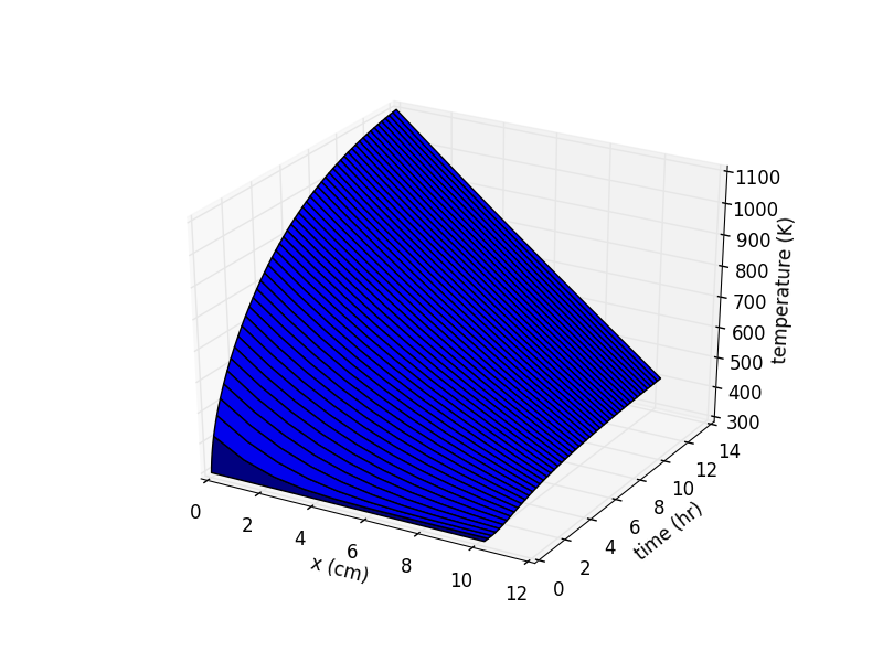
The two plots below show the output of the python script. In the first plot, showing warmup, the initial condition has the wall at a uniform temperature of 300K. Heater power is 1500 W. It takes about 14 hours for the temperature inside to rise to 1100K (830C or 1520F). The x coordinate is distance through the wall from inside (x = 0 cm) to outside (x = 10 cm). A minor note: x actually defines the location of the center of each discrete volume element, so the actual inside and outside wall surfaces are located at -dx/2 and L+dx/2 respectively. But since dx is pretty small, this error is negligible, or at least negligible compared to all the other errors in the model!
![]()
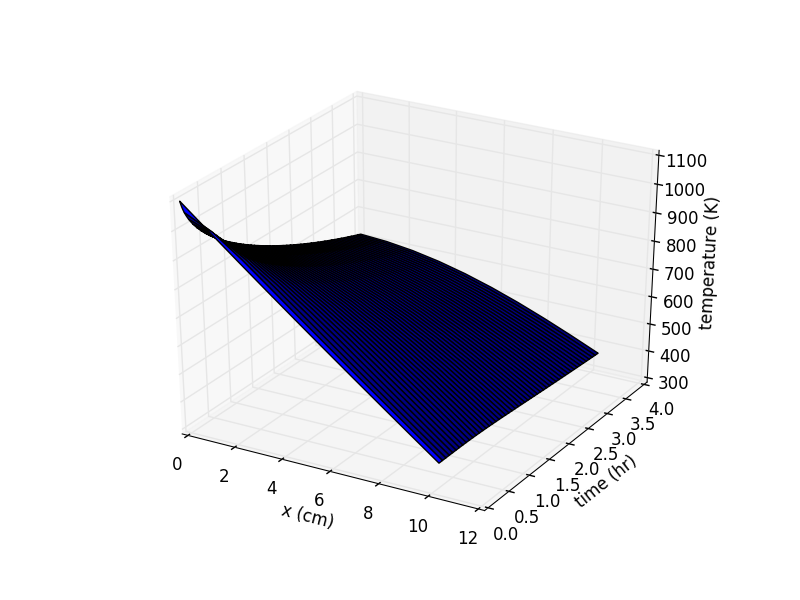
We can solve for the temperature during cooldown. We set the initial condition to the wall temperature profile after warmup, set the heater power to 0W, and iterate again.
![]()
The take home message from this analysis is that the kiln is going to be slow. Fourteen hours is a long time to wait to get up to 1100K. We can hope that perhaps the model is conservative and the kiln will heat up faster. Or perhaps we can look at ways to increase the heater power to get a higher temperature.
 Matt Moses
 After firing, the clay objects turned a deep red. The red color apparently indicates a high iron content in the clay, which according to some of the readers, can cause problems for the nichrome heater wire. So I may need to think about ways to insulate the nichrome from the bricks for long term use...
 As an aside, the extra heater wiring was installed with the help of some clay bead insulators:
 There are about 20 turns per inch, so we need to wind 250/20 = 12.5 inches of tightly wound coil. This will then get stretched out for the final installation in the kiln.
 The first coil was a little longer than 12.5, so the second coil turned out a little shorter:
 It's easiest to stretch out the coil by clamping one end in a vice and then (carefully) pulling the other end slowly and steadily with pair of pliers.
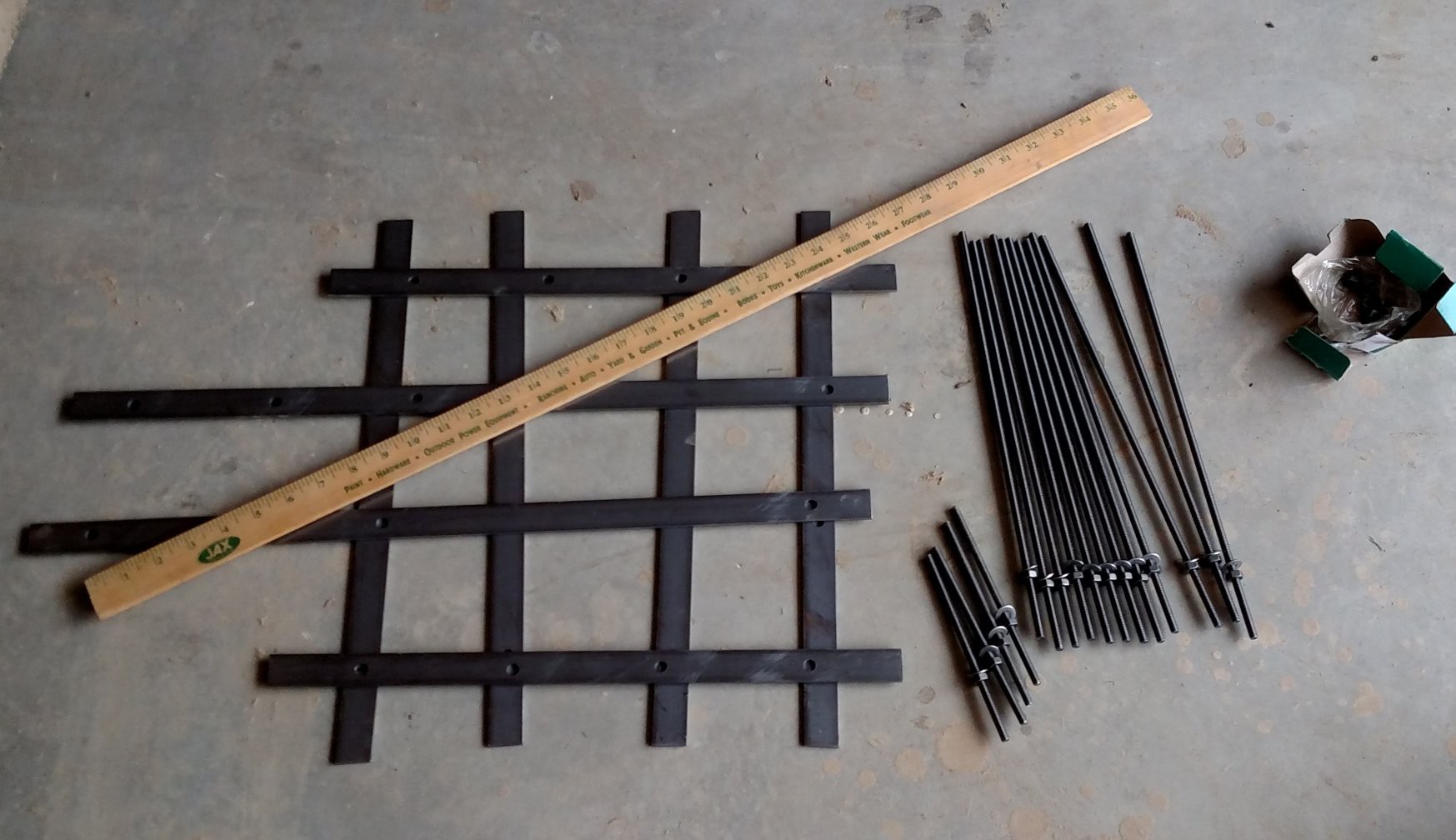 Getting started...
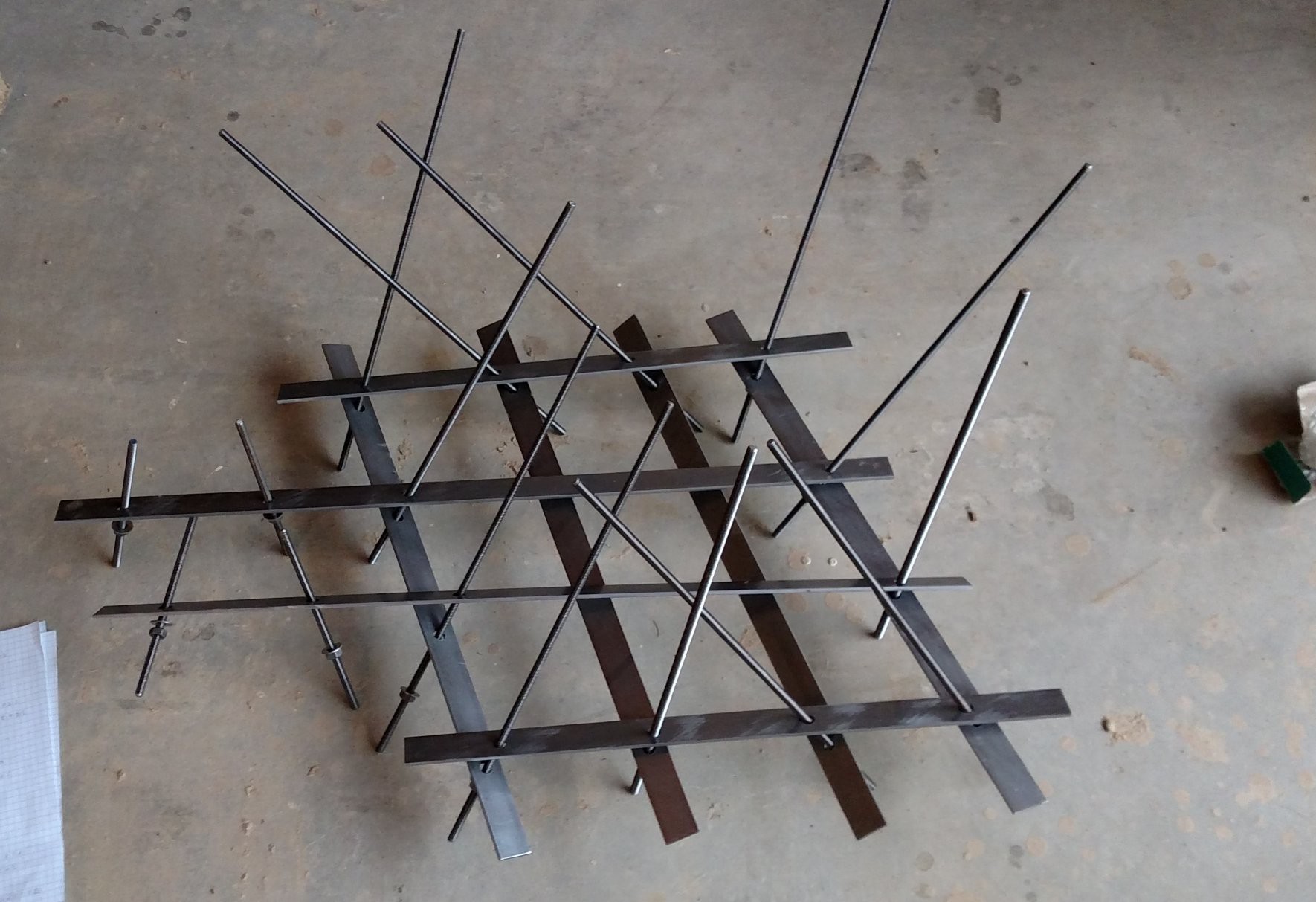 A real spaghetti mess
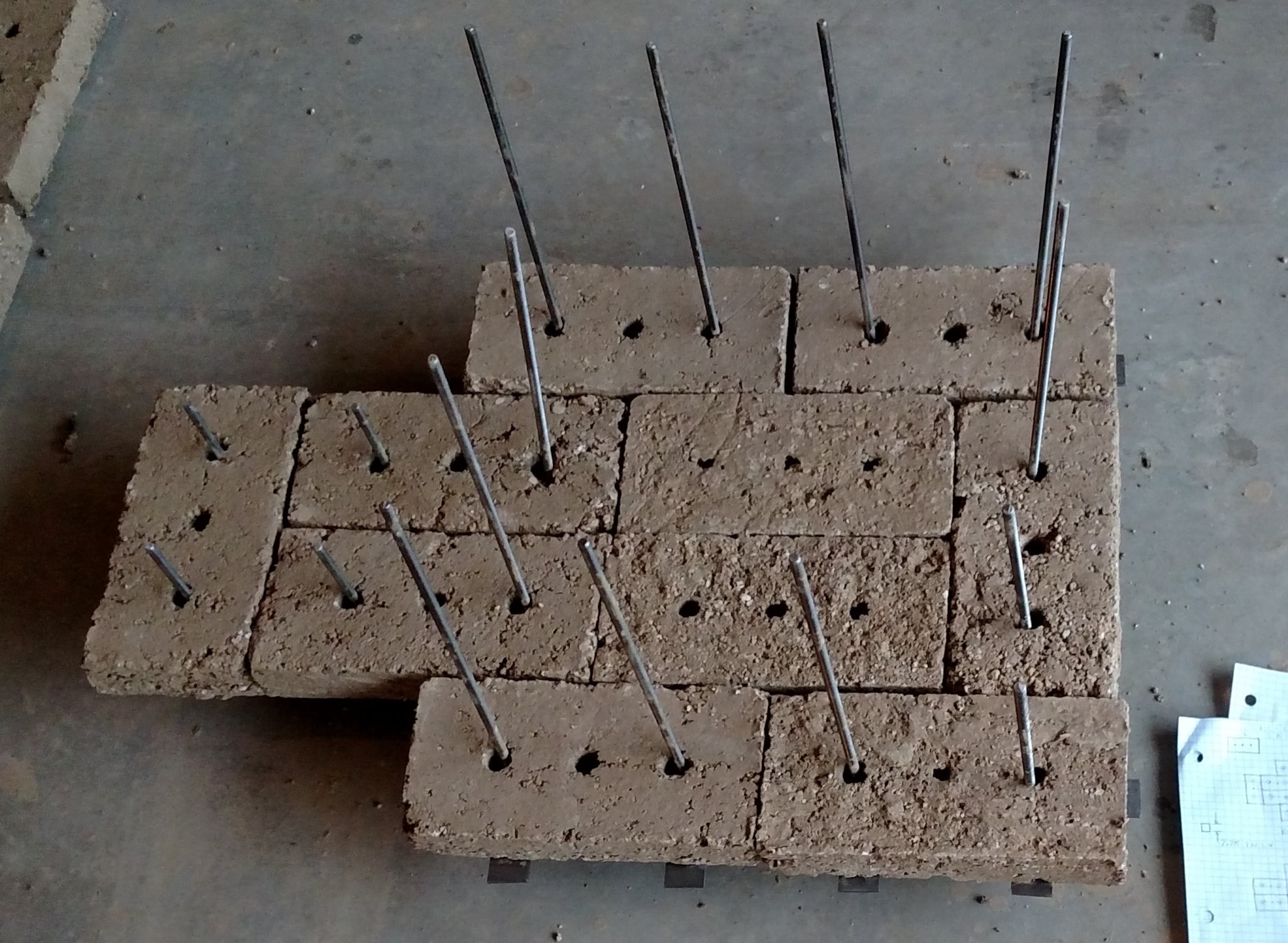
 Brick layer four
 Lid
Lid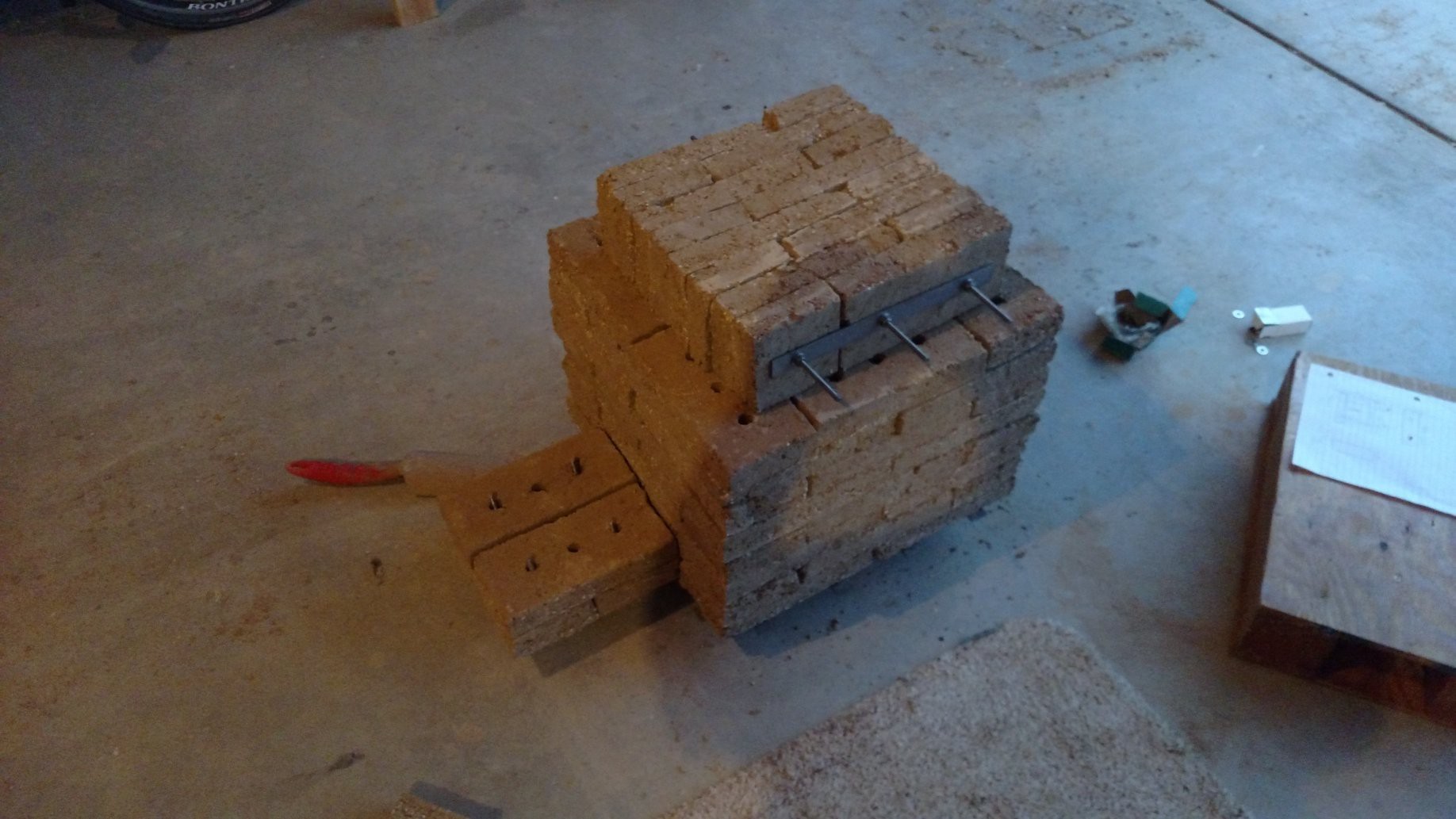 Fitupt Test Complete!
 So the pitch is 3.4mm (0.134 inches). It should work out fine to wind this by hand on the lathe. Stay tuned for that in a later update!