Mark Mullin
-
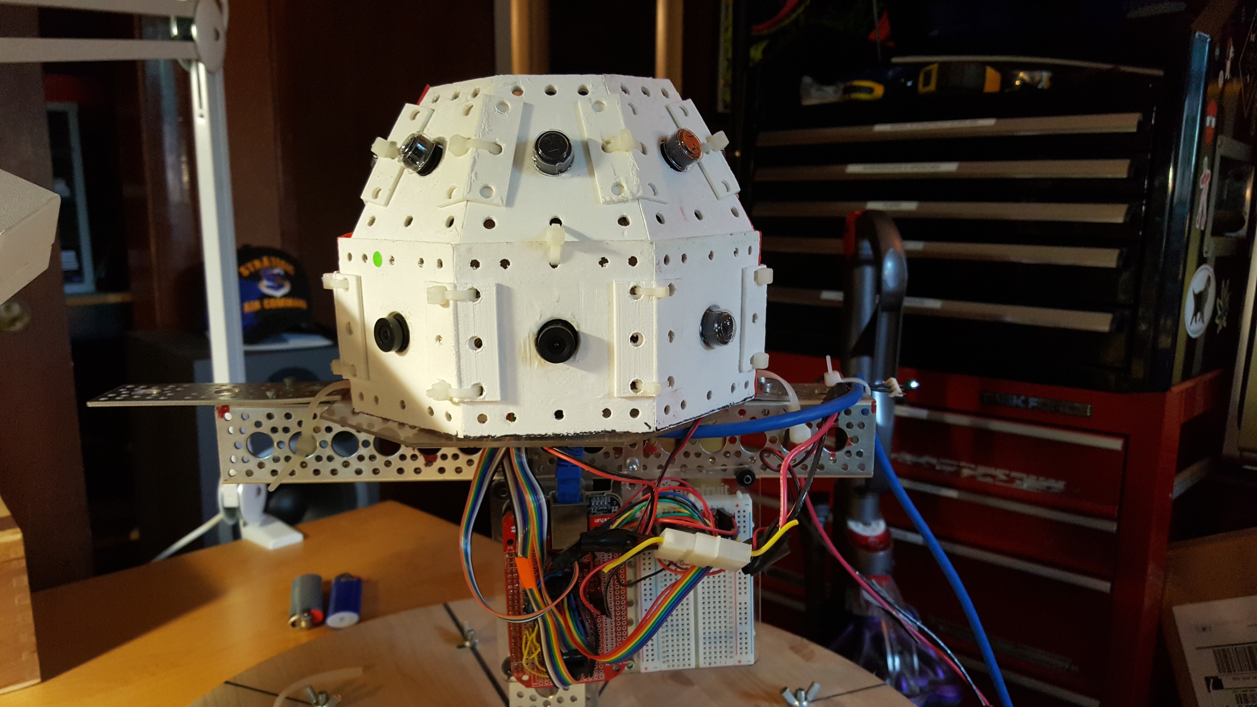
We're coming in.... fast, hot, and heavy....... uggh
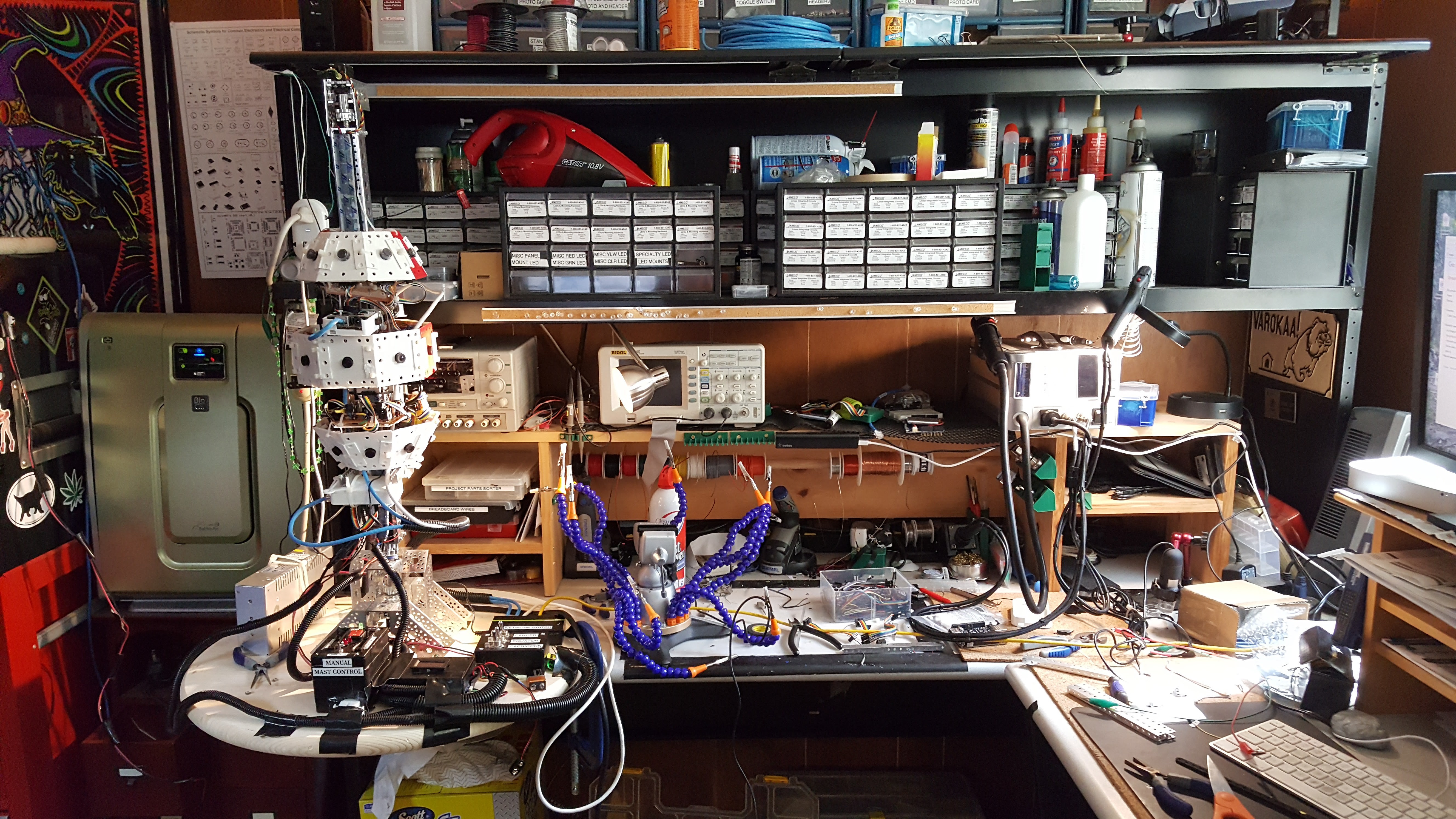
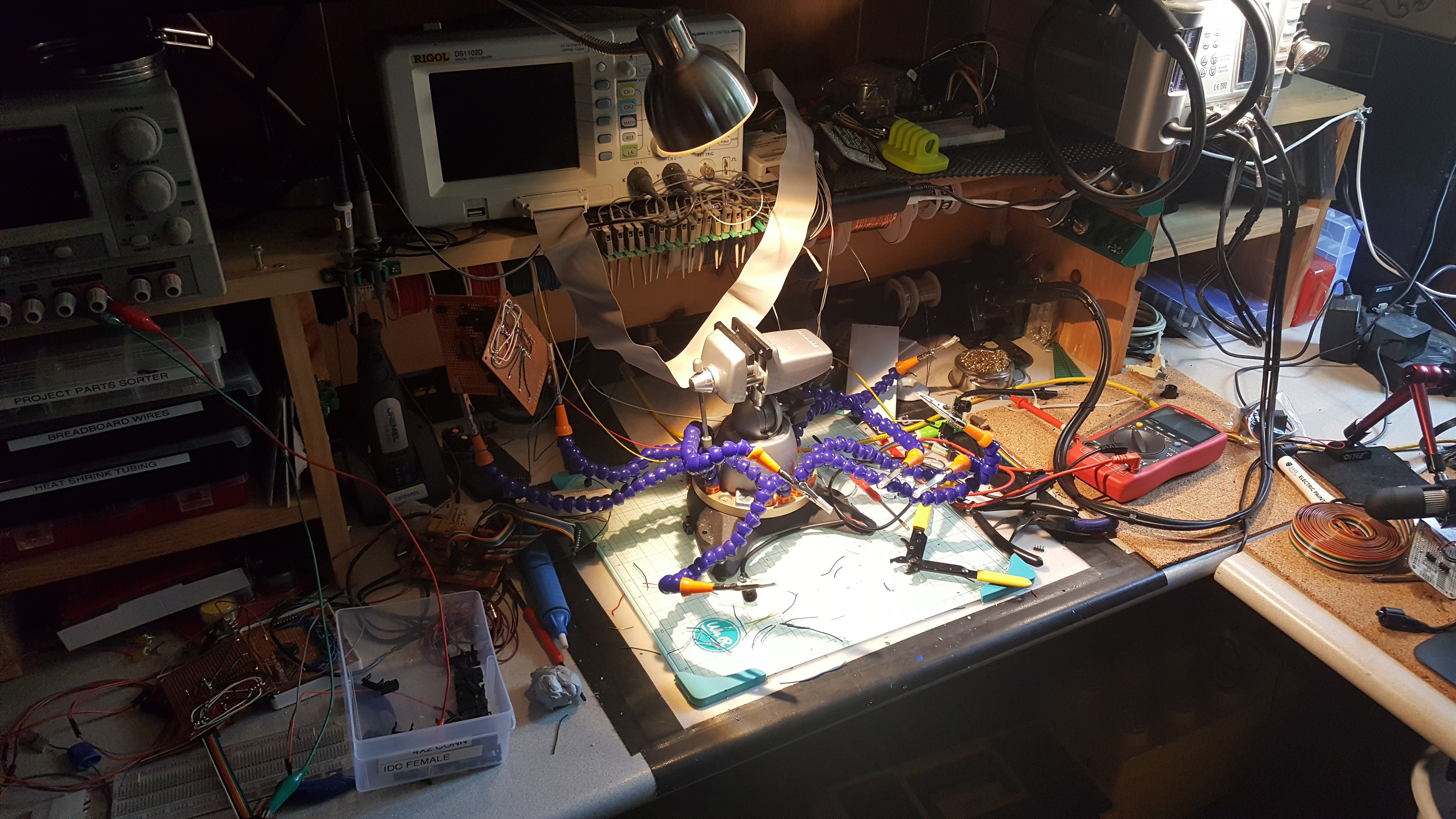
08/22/2017 at 17:00 • 0 commentsQuick update - the entire system is integrated, now running on onboard power - my workroom looks like a bomb went off in it - here's a pic, more details to come
![]()
-
Dover Mini Maker Faire in less than 2 weeks
08/15/2017 at 11:57 • 1 commentOnly a moment for a quick update, but things have been progressing nicely - the Quamera is going out in public on August 26th at the Dover Mini Maker Faire - if you've the interest and are in range of the NH seacoast, I would enjoy meeting you.
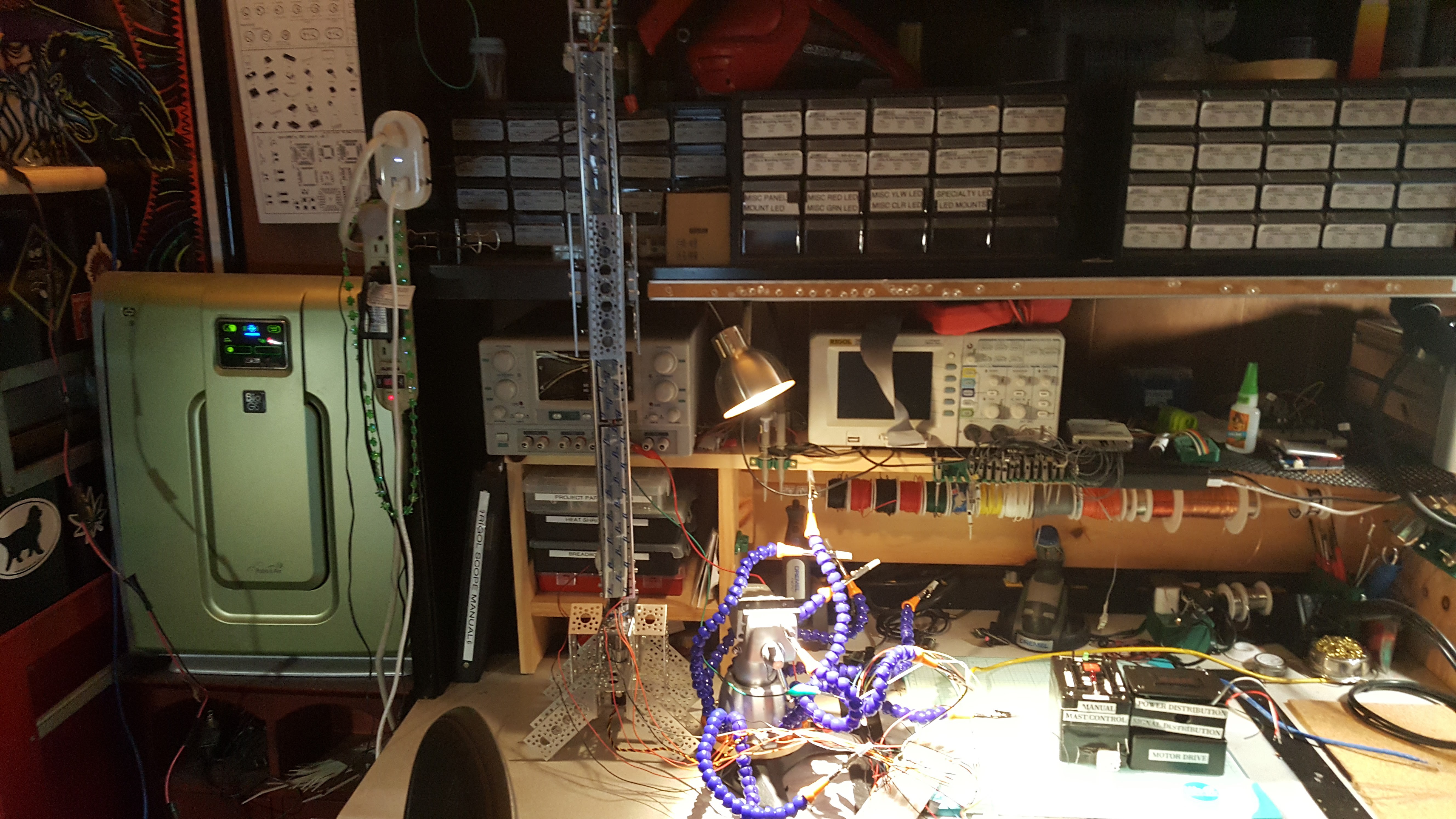
OK, the robot mast is done and operational - you can see it on the right side of this picture, the tall metal stick
![]()
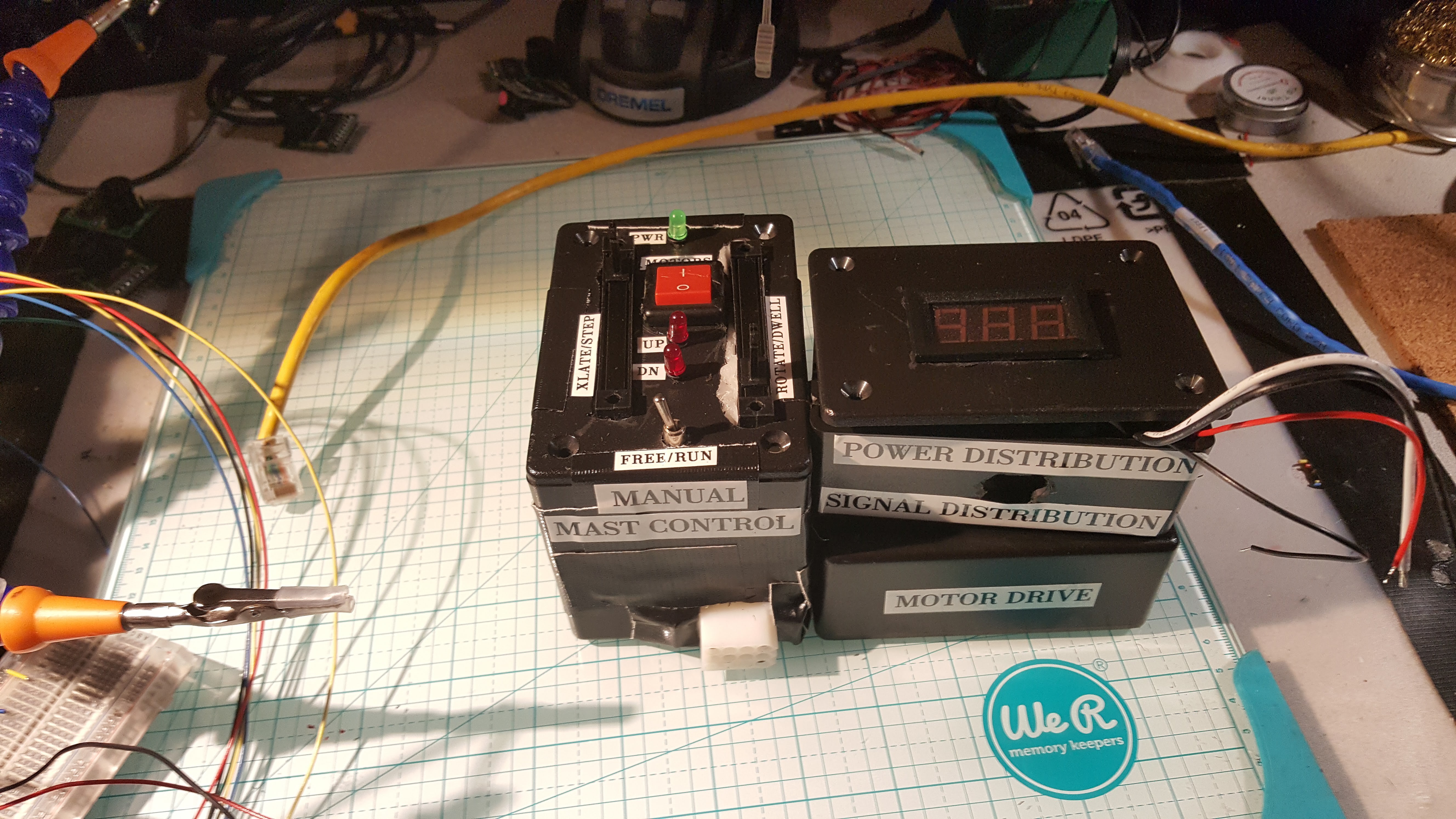
Here's the control panel for the mast and power distribution close up - can't be taking bare wires out in public :-)
![]()
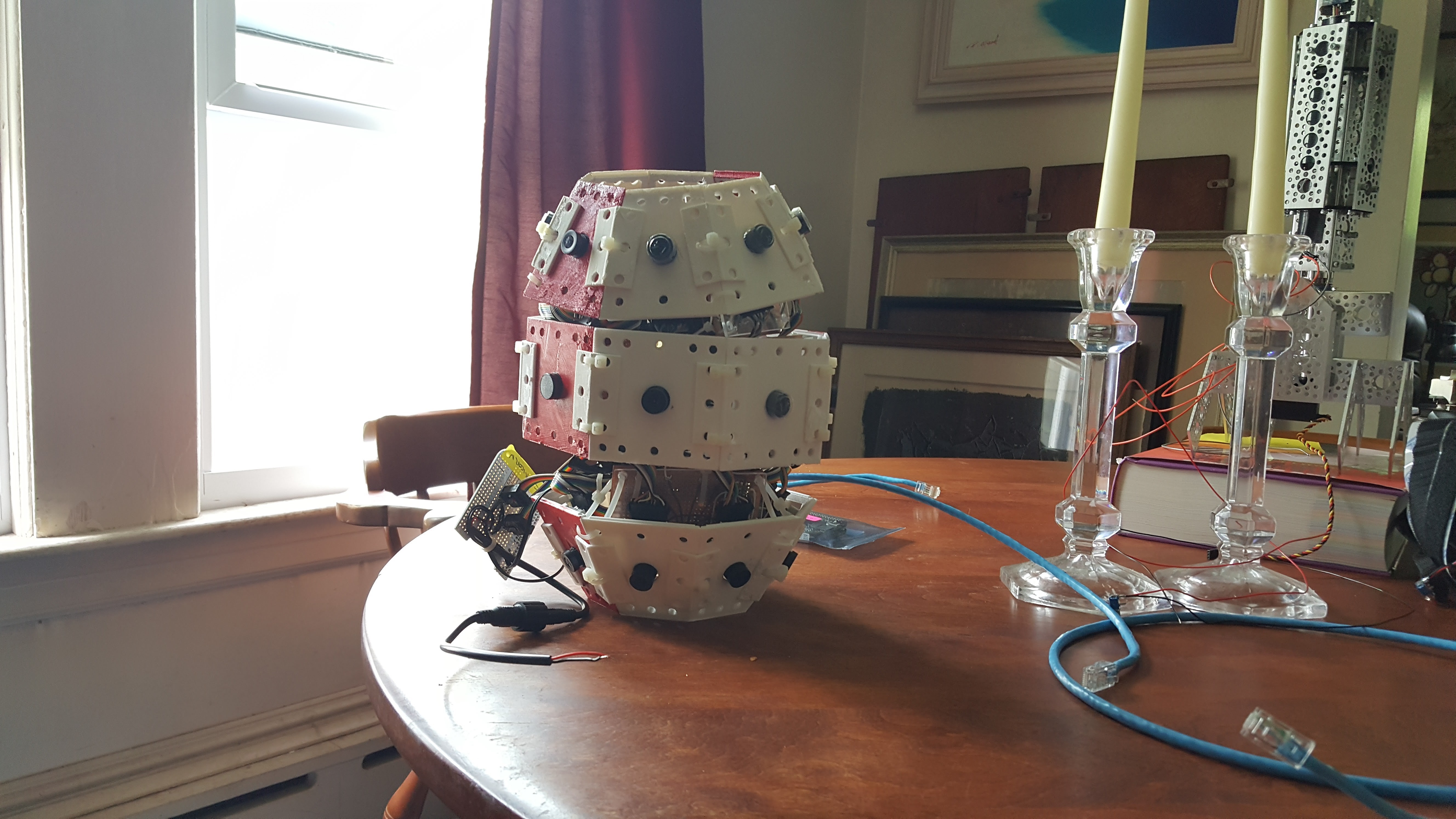
And this sad stack is the three camera rings - I've just perched them on top of each other, first time I've had the physical sense of their volume - when I started I thought the prototype would be the biggest version of the camera, now with the next one clocking in at 36 CPUs, I'm realizing it's the smallest by far . You can also see part of the mast at the right with the camera armature at the bottom (thats the part that goes up and down, the whole mast rotates)
![]()
I must admit, when I took this picture, I immediately thought of this.....
![]()
-
Cancer Ring assembled
08/02/2017 at 02:12 • 0 commentsThe Cancer ring is assembled and the bank controllers and Beaglebone for it are operational .... should have the Capricorn ring within the week
![]()
The rig is fundamentally noisy, but I just decided to overpower it, since we're switching cameras, bussing, etc in the upcoming generation - so this is just a math data generator when you get right down to it - if you want to see how noisy, check this
-
We have a visionary thinker
07/26/2017 at 17:33 • 2 commentsI met Kris Kitchen when I first got involved in Google's Project Tango, and was always impressed with his ability to see the technological forest through the implementation trees. I am very happy to report he's joined the project as its official visionary, so he can poke me with things I never think about when I'm down in the weeds! Welcome, Kris.
-
Full Camera Assembly "Real Soon Now"™
07/24/2017 at 00:46 • 0 commentsWell, turns out I needed another two bank controller cards, as I just couldn’t tear down the test equatorial ring - I need to have something running. That said, of course the wiring has changed between versions.
So here’s the complete set of bank controller cards for the new camera
![]()
The white card at the bottom is the new BBB cape, which connects a BBB to two bank controllers and provide primary power distribution to both the BBB and the 8 cameras and associated vitamins.
Here’s a view of the front of the cape.
![]()
Power comes in from the connector dangling down in the middle. The connector is waterproof, allowing for external power to be external power, instead of wedging enough batteries into the camera enclosure to make it a little too bomb like for my comfort. The two black cables at the right deliver power to each of the two bank controllers, and the 2 4x2 connectors at the bottom are for the ribbon cable that connects each bank controller to the BBB.
Here’s a view of the back.
![]()
The two connectors with their pins gnawed off were a mistake. I was just too tired at that point to unsolder it, as it was both on the wrong side and wrong end of the card. The one thing I’ve noticed with all the busses I have is that you really really really have to pay attention to symmetry and you’re still likely to screw up sometimes.
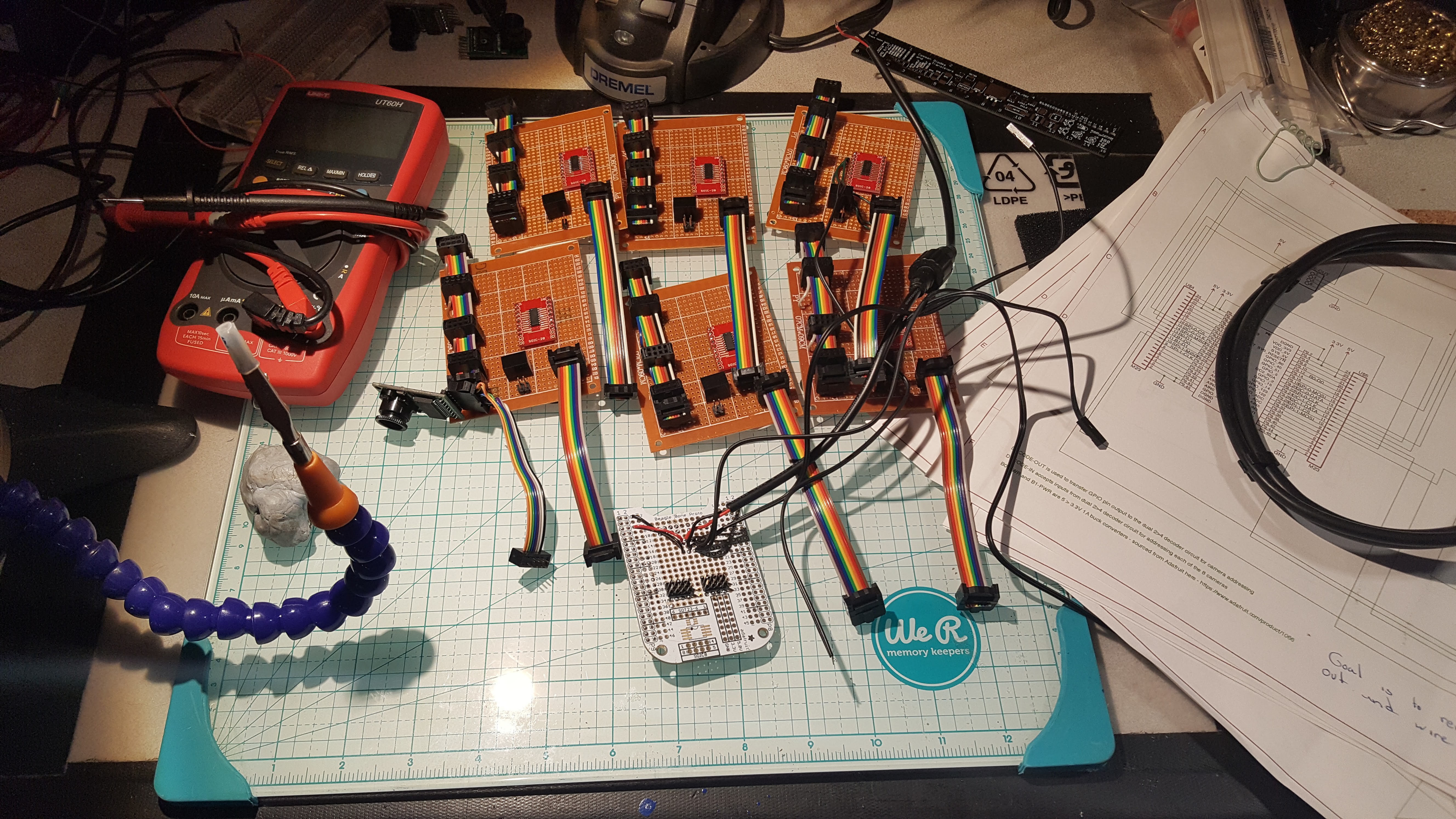
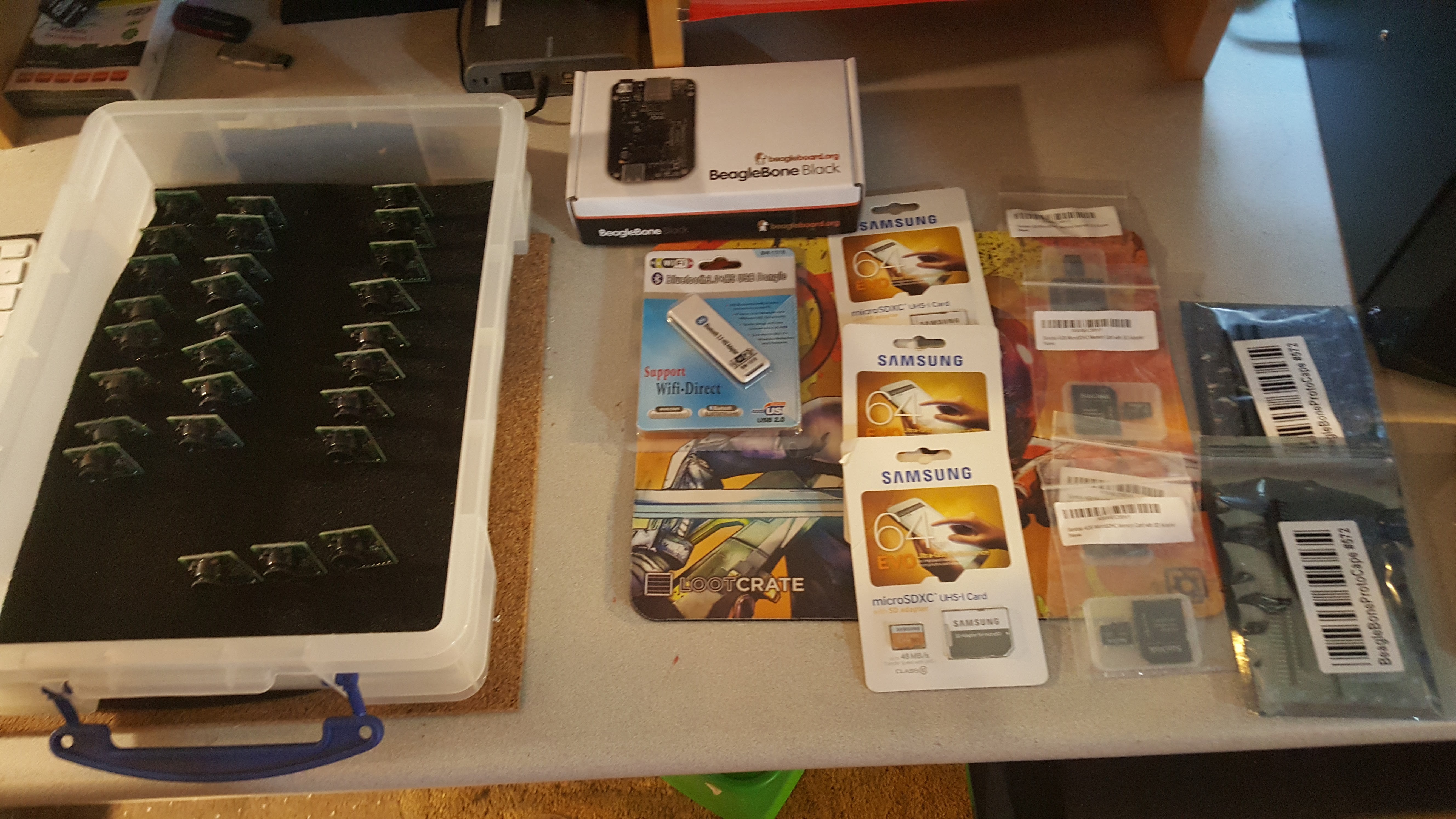
So now we move on to final assembly – of course one part of that is another shopping expedition, both to replace seriously depleted parts and to get the final missing bits. Here’s what’s on hand at present.
![]()
On the left are the 24 cameras for the three rings, and 3 spares. I hope that’s enough, but probably not. One BBB is at center top, 2 more need to come. The USB wifi stick attaches to the Jetson (not shown, the dev rig lives in a tangle of cables) and is used for control and diagnostics - the 3 64GB cards are used as temporary data stores for the fused hypersphere data, and the 4GB cards are used for setting the BBB eMMC. Finally, at the right are the BBB proto cape cards I still have to assemble.
Some Historical Bits, if you so care.
Given the amount of mayhem, I had to clean up the lab cause this is what it looked like.
![]()
In doing that, I re-encountered a number of earlier constructions used to proof out the basic concept and circuits.
First Bank Controller
The first bank controller was constructed using level shifters from Adafruit, and the whole system ran at 5V. It was noisy as hell. Here’s the backside. Seems I’ve gone through two tips at this point with all the soldering I’ve done.
![]()
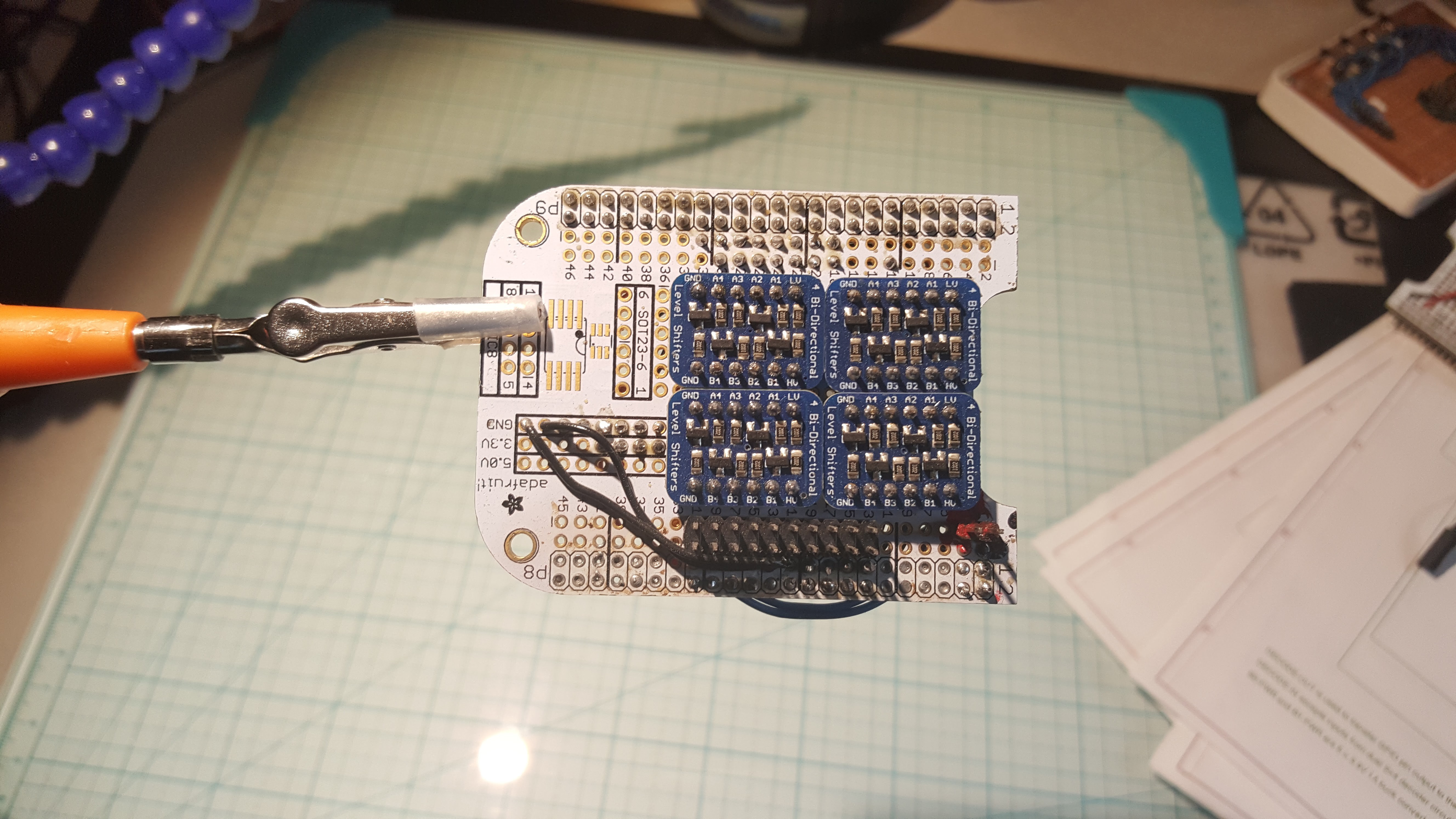
Here’s the front side – all the need for level shifters went away after I switched to 3.3V for everything except the main 5V rail.
![]()
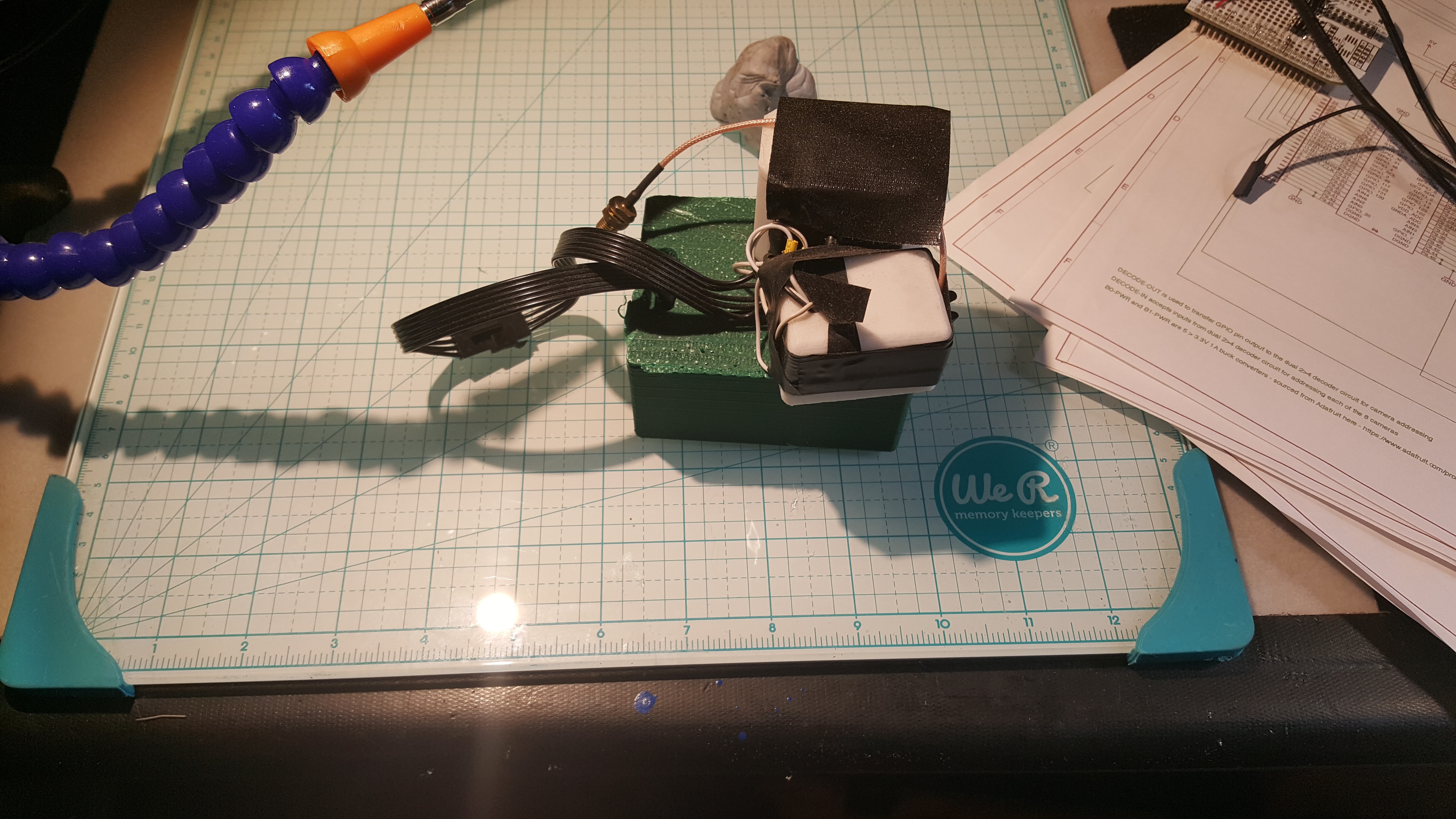
Test GPS/IMU Assembly
This went on a bunch of hikes with me – the green box at the bottom has an Arduino serving as a data logger, the smaller white box at the front contains an IMU sled, and the larger box at the back with the antenna connector holds a GPS sled.
![]()
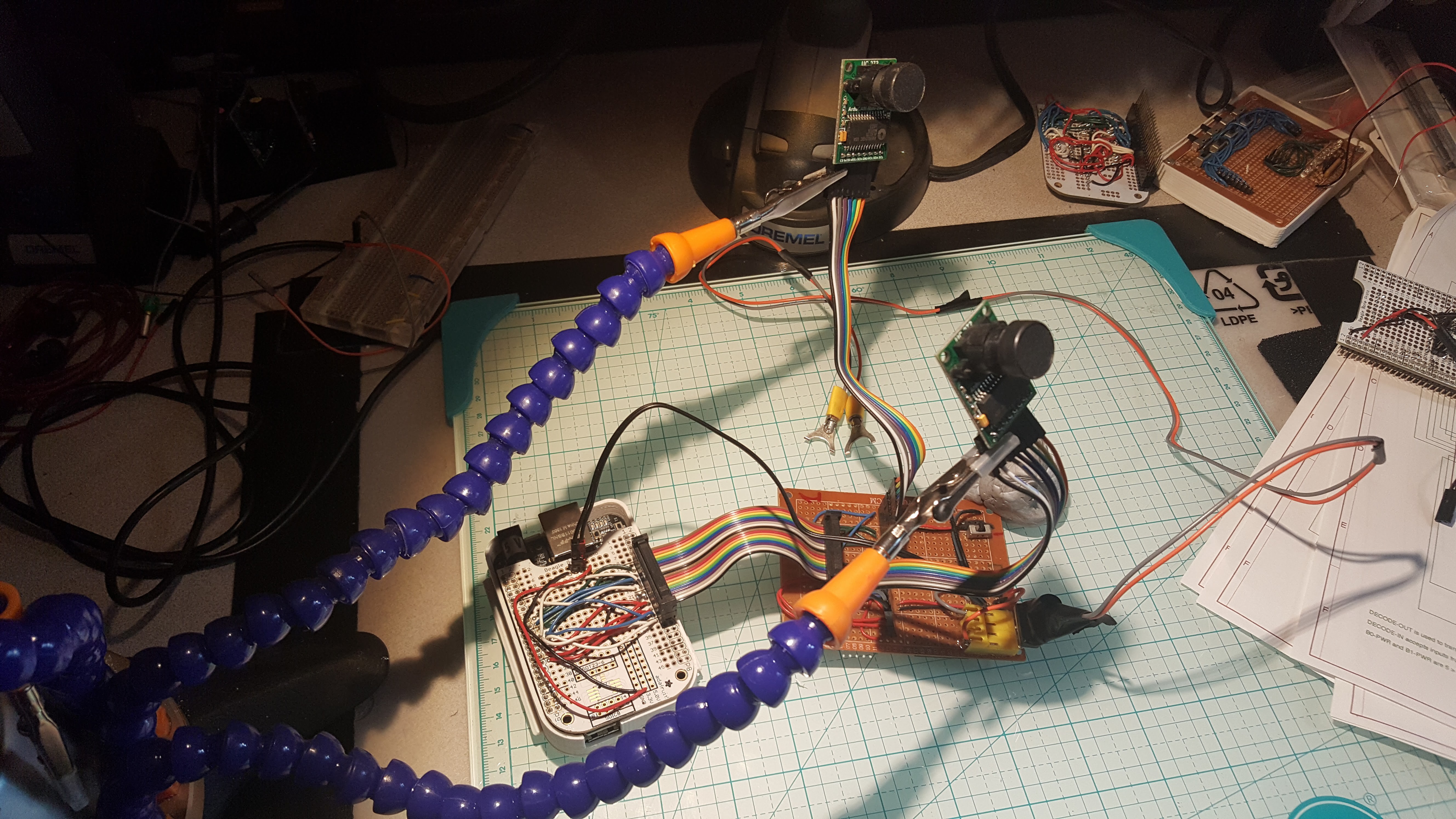
Original 2 Camera Test Platform
The initial bank design was tested with a single hardwired camera on each bank. This tester still works as a basic test platform for grumpy imager assemblies.
![]()
At the left is the BBB with a custom cape that pulls all the necessary signaling onto a 16-conductor ribbon cable. At the right is the camera host board, which splits out the signaling, allows the cameras to be switched in and out of the circuit, and accepts 3.3V power to drive the cameras (yeah, I rebuilt the tester after I learned 3.3V was a better way.
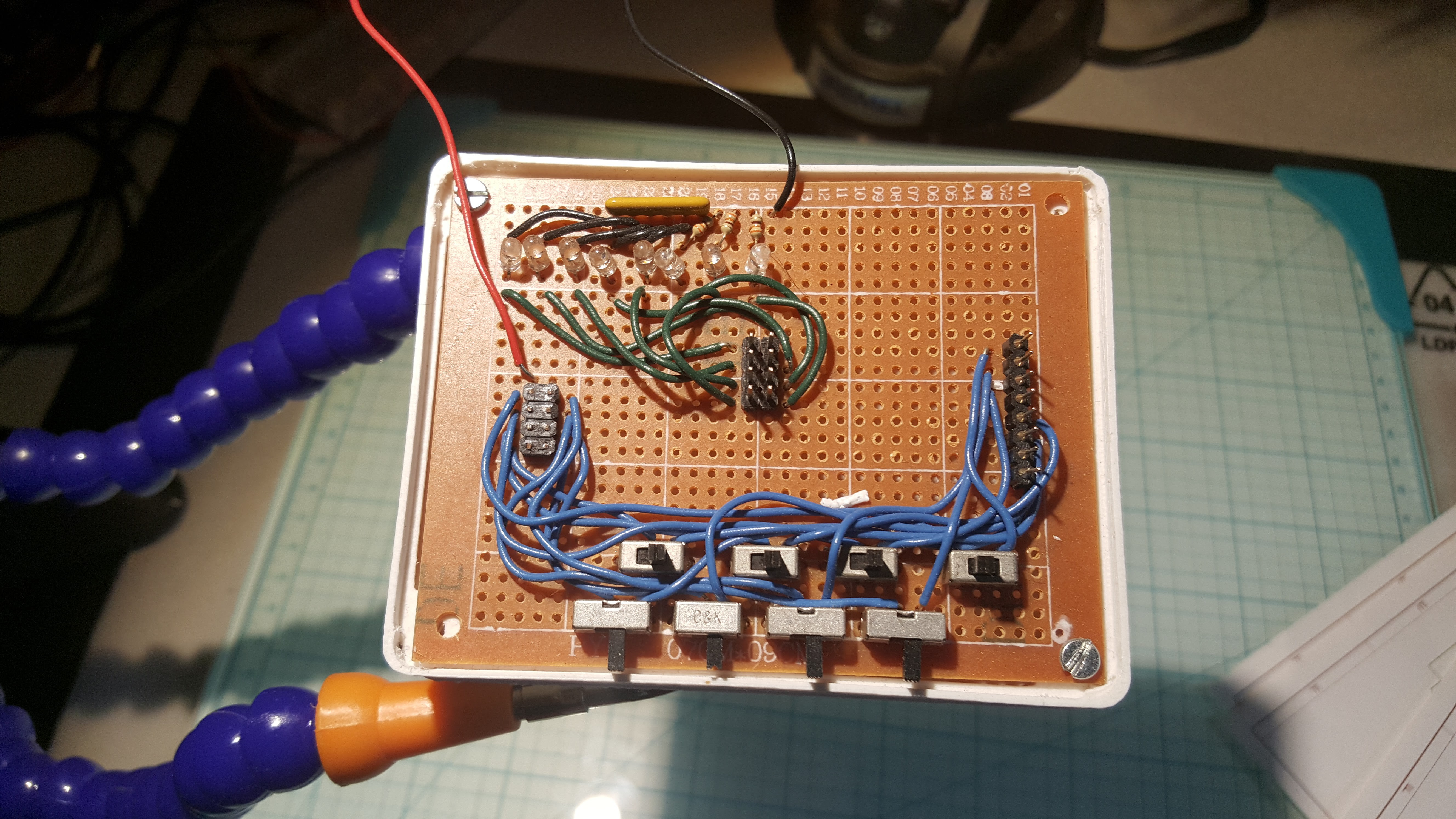
Cable Tester
This is used to confirm that the 4x2 to camera connector cable is correctly wired, by inspecting the led illumination. Still use this puppy, given I need to guarantee 24 new cables aren’t going to deliver voltage on the wrong connection.
![]()
So, the next post, with any luck, will convey status of final assembly. That's gonna be interesting. Then the stupid thing goes mobile in 1D, then in 2D, then in 3D.
-
Full Camera Assembly "Real Soon Now"™
07/24/2017 at 00:46 • 0 commentsWell, turns out I needed another two bank controller cards, as I just couldn’t tear down the test equatorial ring - I need to have something running. That said, of course the wiring has changed between versions.
So here’s the complete set of bank controller cards for the new camera
![]()
The white card at the bottom is the new BBB cape, which connects a BBB to two bank controllers and provide primary power distribution to both the BBB and the 8 cameras and associated vitamins.
Here’s a view of the front of the cape.
![]()
Power comes in from the connector dangling down in the middle. The connector is waterproof, allowing for external power to be external power, instead of wedging enough batteries into the camera enclosure to make it a little too bomb like for my comfort. The two black cables at the right deliver power to each of the two bank controllers, and the 2 4x2 connectors at the bottom are for the ribbon cable that connects each bank controller to the BBB.
Here’s a view of the back.
![]()
The two connectors with their pins gnawed off were a mistake. I was just too tired at that point to unsolder it, as it was both on the wrong side and wrong end of the card. The one thing I’ve noticed with all the busses I have is that you really really really have to pay attention to symmetry and you’re still likely to screw up sometimes.
So now we move on to final assembly – of course one part of that is another shopping expedition, both to replace seriously depleted parts and to get the final missing bits. Here’s what’s on hand at present.
![]()
On the left are the 24 cameras for the three rings, and 3 spares. I hope that’s enough, but probably not. One BBB is at center top, 2 more need to come. The USB wifi stick attaches to the Jetson (not shown, the dev rig lives in a tangle of cables) and is used for control and diagnostics - the 3 64GB cards are used as temporary data stores for the fused hypersphere data, and the 4GB cards are used for setting the BBB eMMC. Finally, at the right are the BBB proto cape cards I still have to assemble.
Some Historical Bits, if you so care.
Given the amount of mayhem, I had to clean up the lab cause this is what it looked like.
![]()
In doing that, I re-encountered a number of earlier constructions used to proof out the basic concept and circuits.
First Bank Controller
The first bank controller was constructed using level shifters from Adafruit, and the whole system ran at 5V. It was noisy as hell. Here’s the backside. Seems I’ve gone through two tips at this point with all the soldering I’ve done.
![]()
Here’s the front side – all the need for level shifters went away after I switched to 3.3V for everything except the main 5V rail.
![]()
Test GPS/IMU Assembly
This went on a bunch of hikes with me – the green box at the bottom has an Arduino serving as a data logger, the smaller white box at the front contains an IMU sled, and the larger box at the back with the antenna connector holds a GPS sled.
![]()
Original 2 Camera Test Platform
The initial bank design was tested with a single hardwired camera on each bank. This tester still works as a basic test platform for grumpy imager assemblies.
![]()
At the left is the BBB with a custom cape that pulls all the necessary signaling onto a 16-conductor ribbon cable. At the right is the camera host board, which splits out the signaling, allows the cameras to be switched in and out of the circuit, and accepts 3.3V power to drive the cameras (yeah, I rebuilt the tester after I learned 3.3V was a better way.
Cable Tester
This is used to confirm that the 4x2 to camera connector cable is correctly wired, by inspecting the led illumination. Still use this puppy, given I need to guarantee 24 new cables aren’t going to deliver voltage on the wrong connection.
![]()
So, the next post, with any luck, will convey status of final assembly. That's gonna be interesting. Then the stupid thing goes mobile in 1D, then in 2D, then in 3D.
-
Upper and Lower 45° Rings imminent
07/09/2017 at 20:18 • 0 commentsIt’s been a long hard weekend; however, the finish line is now in sight. At least for Version 1, which is now projecting a somewhat shortened lifetime…..
The single ring proof of concept being completed, the next step is to bring the entire spherical view online and begin solving error across both axes. This is primarily a mechanical exercise at this point, as the single ring tests show clearly the system can differentiate between parallax and non-parallax points (OK, it picks points that play nice as non-parallax points) however it had no means of controlling vertical integration error. With the arrival of the upper and lower 45° rings, it now has complete overlap with the equatorial ring, so overall it gets pretty good measurements as long as you don’t try and get too close to the poles.
To do this, two more Beaglebones have to be added, each controlling 2 banks of 4 cameras each, for a total of 16 new cameras. No new software is needed (yet), as these run exactly the same system as the primary ring, they’re just connected to different cameras.
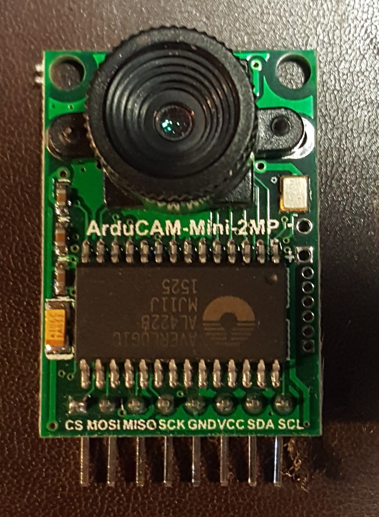
Let’s start at the beginning. Here’s a picture of an ArduCam using a OV2640 sensor, which I source from www.arducam.com - these aren’t the final cameras; they help keep the initial budget under control – the final cameras will also come from Arducam, but they’re bigger, meaner, and unfortunately, more expensive.
![]()
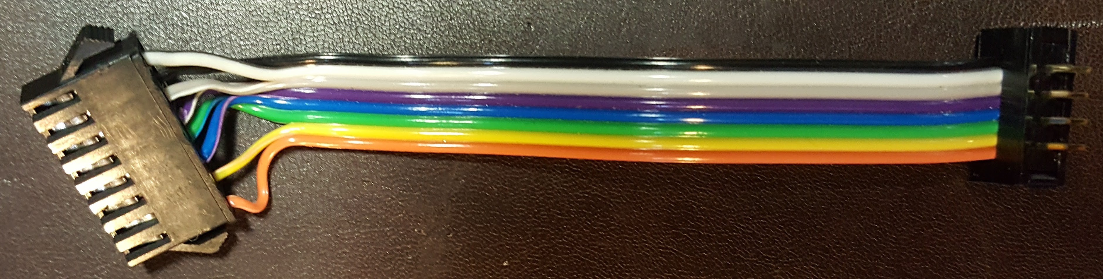
Here’s a picture of a cable that connect the Arducam to a bank controller. If you look closely, you’ll see that the second pair of wires from the bottom and the top pair are swapped. Yeah, I don’t wanna talk about it - rotational symmetry between plugs caused a big problem – since my male header is exposed instead of shrouded (look, those are the terms!) I had to deal with everything getting rotated on me – worked most of it out in my head, but those two puppies were problematic (power and chip select were the key offenders) –this design isn’t going to be repeated in its current form and I’m using up existing stock instead of going broke buying new stuff. Only catch is I have to 3D print a clamp to make sure that connections stay that way.
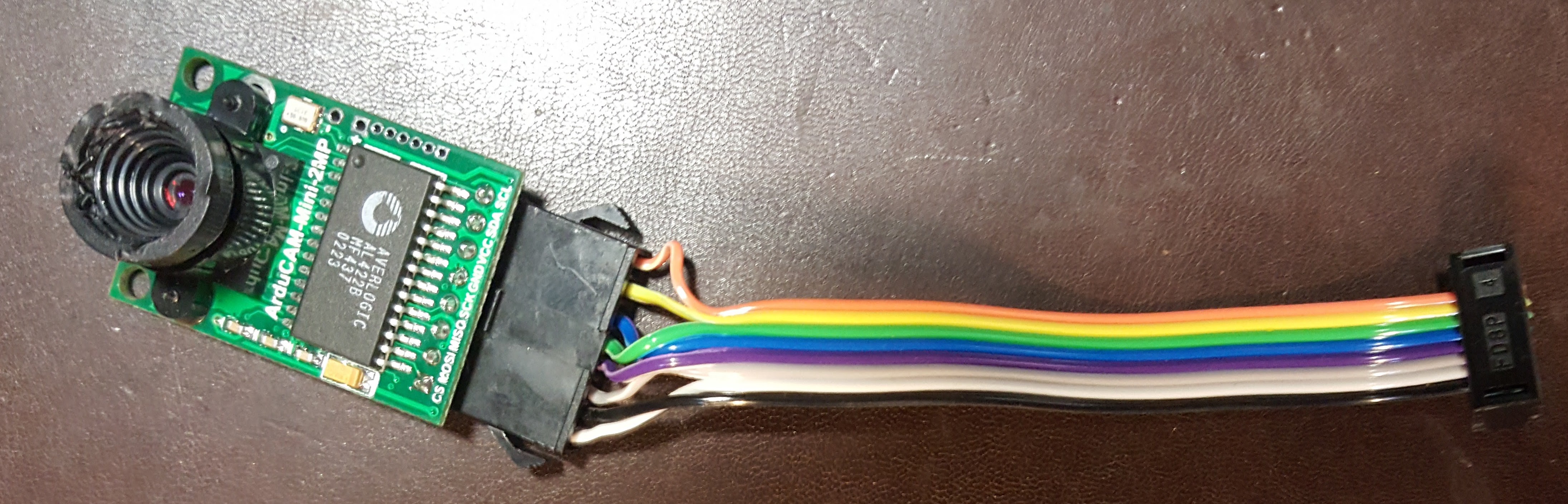
Here’s a picture of an Arducam connected to the cable – I still have a bit of work to do to ensure all pins are well seated and every cable is functional, but at least I’ve got a common pattern to work with – the real concern is that <long string of profanities> JST connectors have lots of problems, one being a short cycle count - so I don’t want to wear the damn things out testing them.![]()
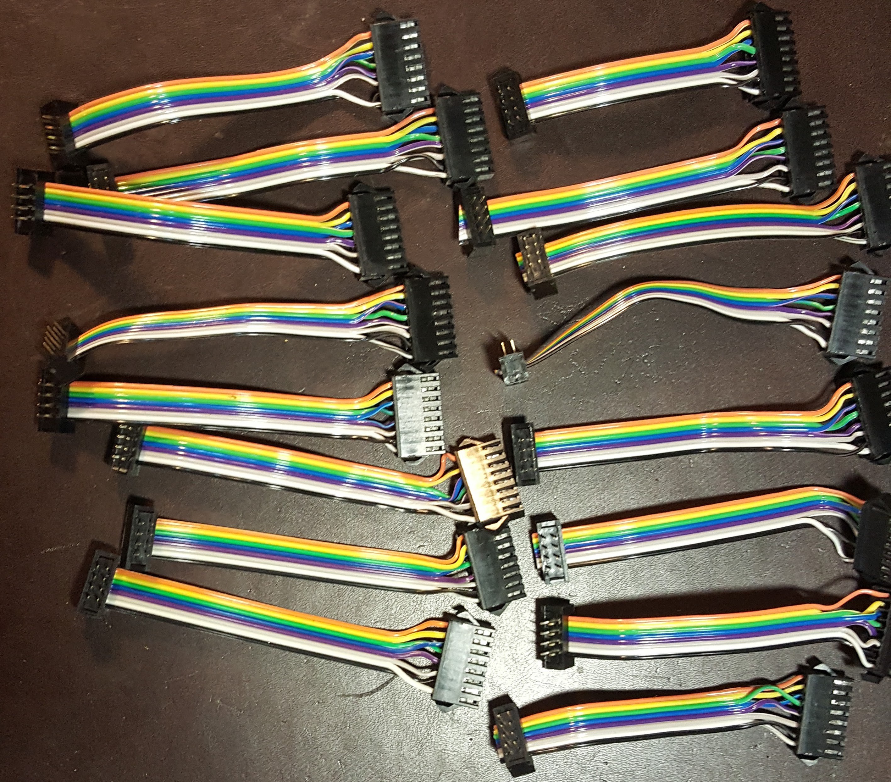
![]() Here’s a picture of all 16 cables. JST connecters have to be
crimped by hand, twice per wire, and lets see that’s 8 wires per camera and 16
cameras - after 128 wires, some multiple
times, etc etc etc I’m truly sick of these damn things. More importantly, I can’t
put it off anymore because it’s all done.
Here’s a picture of all 16 cables. JST connecters have to be
crimped by hand, twice per wire, and lets see that’s 8 wires per camera and 16
cameras - after 128 wires, some multiple
times, etc etc etc I’m truly sick of these damn things. More importantly, I can’t
put it off anymore because it’s all done.
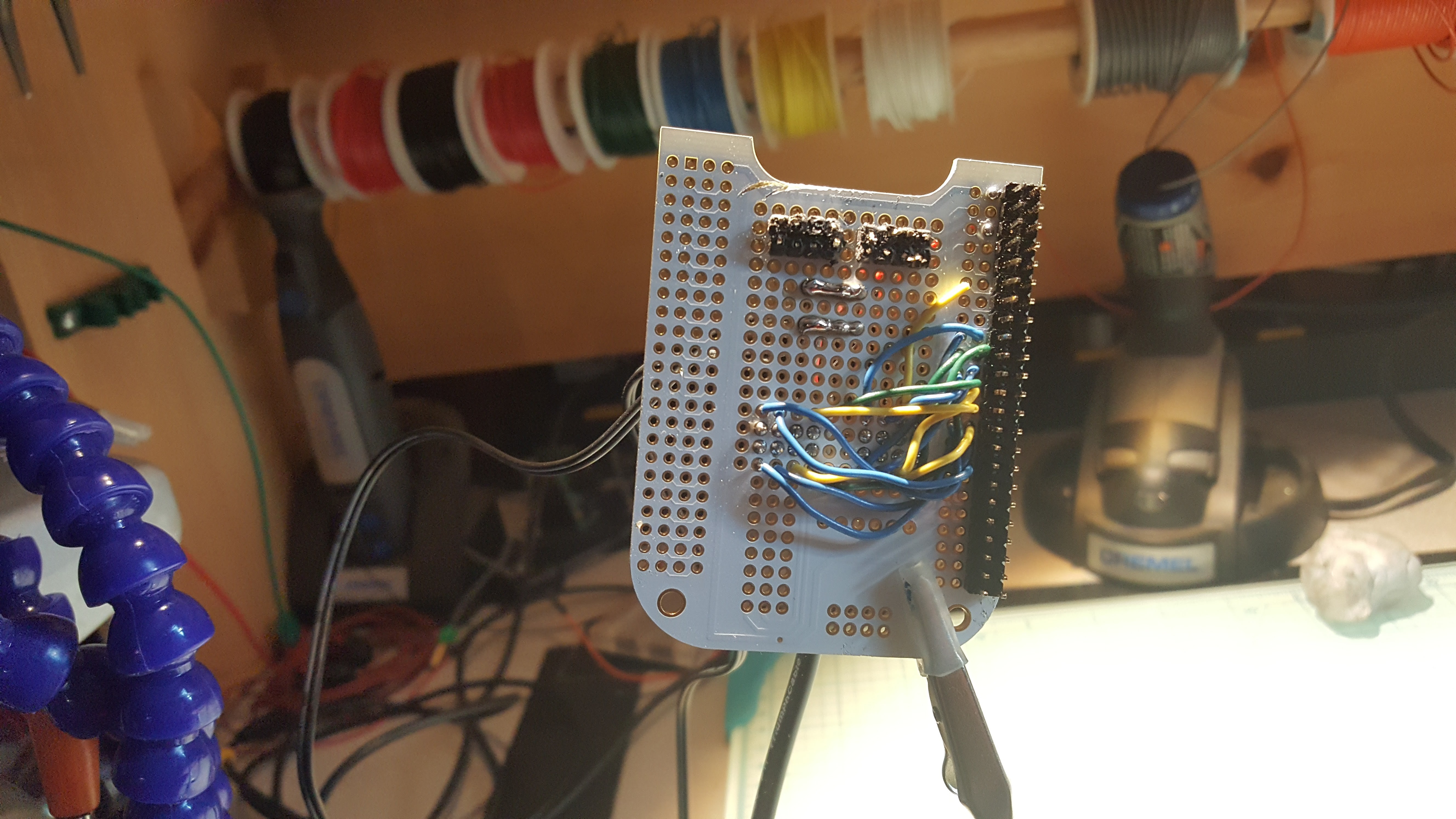
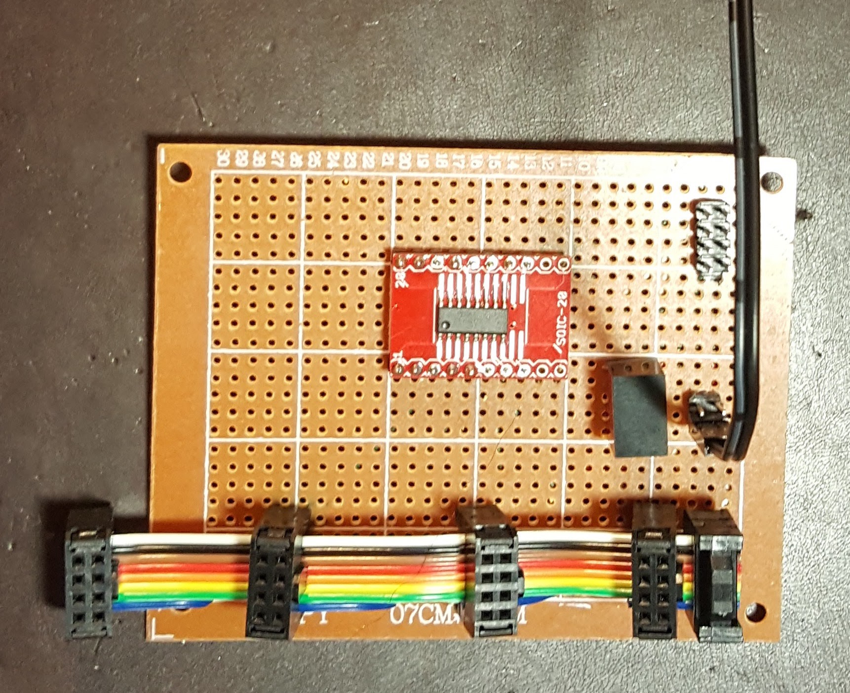
![]() Now that we’ve dispensed with the preliminaries, here’s a
picture of a bank controller. Each BBB
is connected to two bank controllers on independent SPI/I2C bus pairs – this allows
it to drive two cameras in parallel. A
bank controller provides the final interface to the four cameras in a
bank. The red SOIC sled in the middle
(Sparkfun) carries the dual 2-4 decoder described in the previous log
entry. At the top right is the connector
to the BBB cape, which carries one SPI/I2C bus pair, the negative going bank
select signal, and the two data lines that carry the camera select bits. The incoming I2C and SPI buses are directly routed
to the cable at the bottom, and the CS and data lines are routed to one side of
the dual 2-4 decoder.
Now that we’ve dispensed with the preliminaries, here’s a
picture of a bank controller. Each BBB
is connected to two bank controllers on independent SPI/I2C bus pairs – this allows
it to drive two cameras in parallel. A
bank controller provides the final interface to the four cameras in a
bank. The red SOIC sled in the middle
(Sparkfun) carries the dual 2-4 decoder described in the previous log
entry. At the top right is the connector
to the BBB cape, which carries one SPI/I2C bus pair, the negative going bank
select signal, and the two data lines that carry the camera select bits. The incoming I2C and SPI buses are directly routed
to the cable at the bottom, and the CS and data lines are routed to one side of
the dual 2-4 decoder.
![]() The pigtail at the center right brings power and ground into the circuit. This is done on a separate cable because the system operates at 3.3V but distributes power at 5V. The vertical rectangular box to the left of the power connector is a Traco 5.0 to 3.3V converter and is used to provide power to the decoder chip (inconsequential) and the cameras (at up to 1A each, extremely damn consequential)
The pigtail at the center right brings power and ground into the circuit. This is done on a separate cable because the system operates at 3.3V but distributes power at 5V. The vertical rectangular box to the left of the power connector is a Traco 5.0 to 3.3V converter and is used to provide power to the decoder chip (inconsequential) and the cameras (at up to 1A each, extremely damn consequential)This design reflects a number of conversations with Lee at Arducam about performance and bandwidth issues with respect to SPI buses, and to some degree I2C as well. While the cable assemblies were all eyeballed and adjusted to deal with soldering challenges, the goal was to use the minimal amount of wire, to ensure the wiring was as uniform as possible, and to in general, stop trying to compound an already difficult (noisy) situation. We shall see how well this works, however I do already know that a relatively clean design will net you 4Mhz bandwidth. There’s a lot of data here though………….
![]()
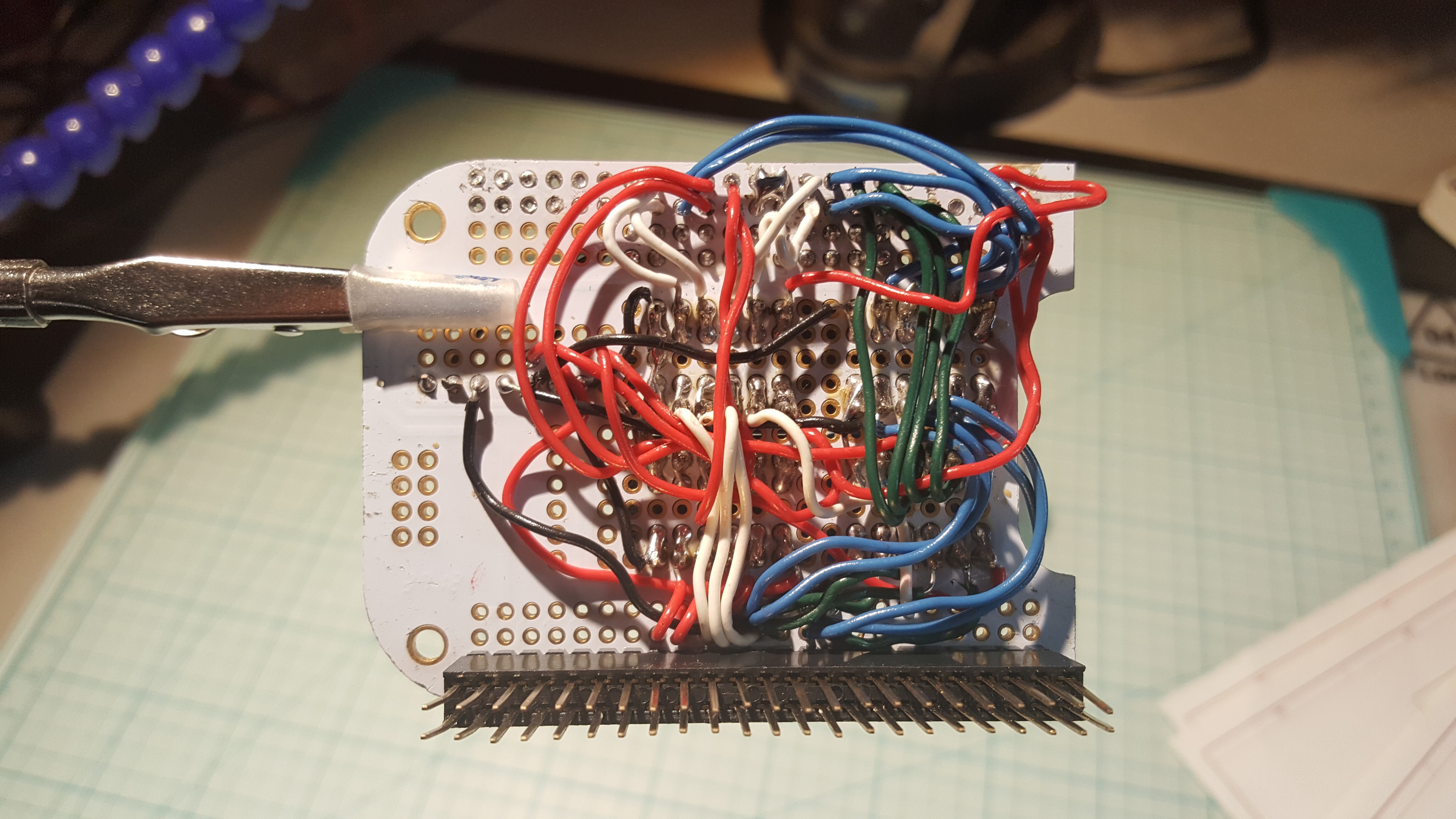
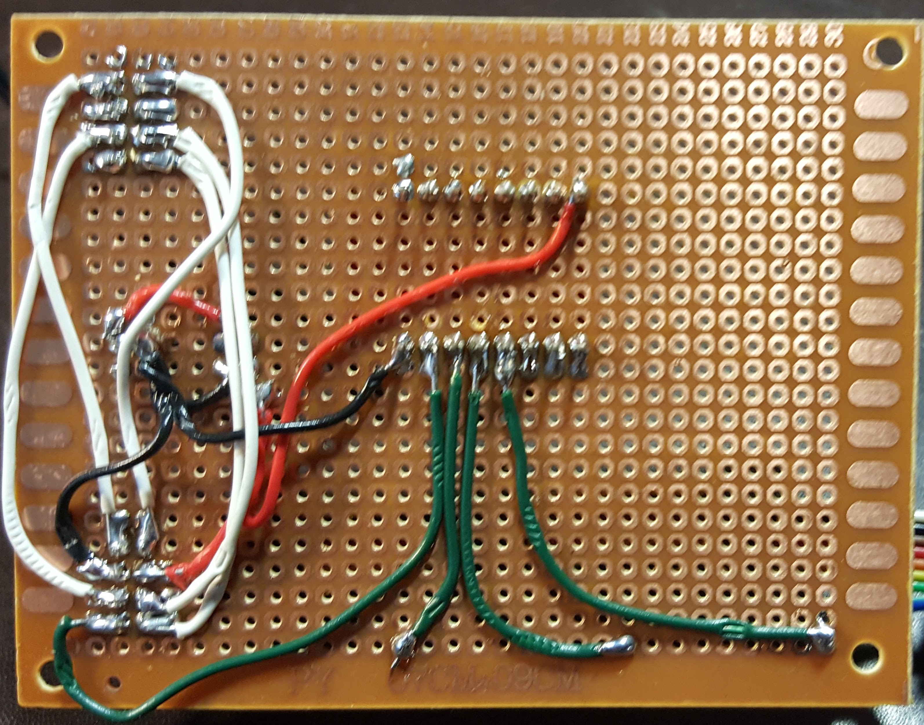
Here’s a view of the back of a bank controller. Red is 5V and 3.3V power, black is ground, green is camera select decode, and white is common SPI and I2C bussing. At the beginning of this process my smooth hemostats decided to die by fracturing a jaw and so there’s teeth marks everywhere from the toothed hemos. It isn’t that I press that hard, a busted hemo jar notwithstanding – it’s that as you do the soldering, there’s enough heat conduction the insulation gets soft and you end up goring it. Yes, the soldering could be better, but nobodies volunteering to be a lab assistant other than my son, and he doles that out carefully.
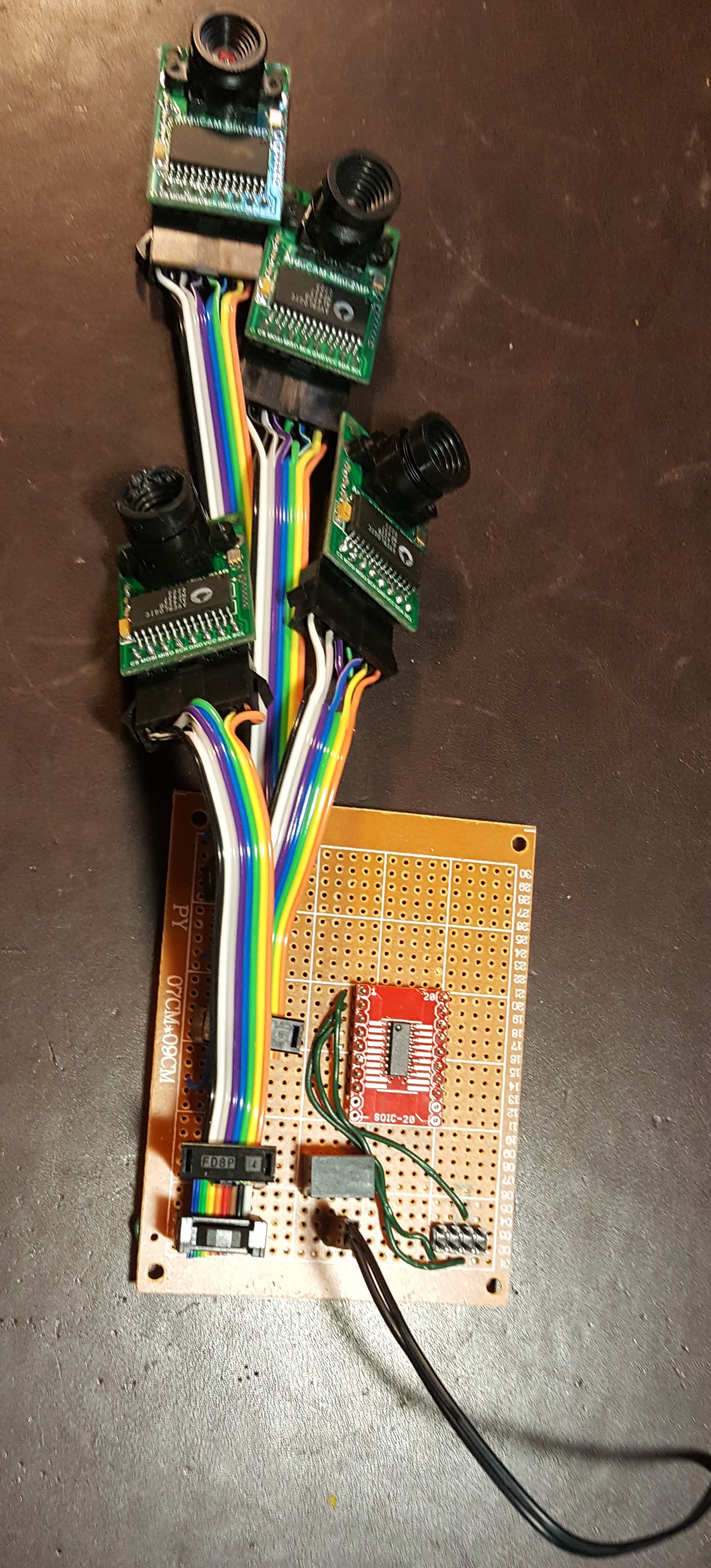
Here’s what a fully populated bank controller looks like, minus the yet to be 3D printed clamps to keep the damn cables from falling apart. Basically, when the BBB control software spins up it fragments into two pieces, each controlling an independent SPI/I2C bus pair. And then each piece races around in a circle, reading the 4 cameras on the bank controller it’s connected to in an endless game of circling the drain
![]()
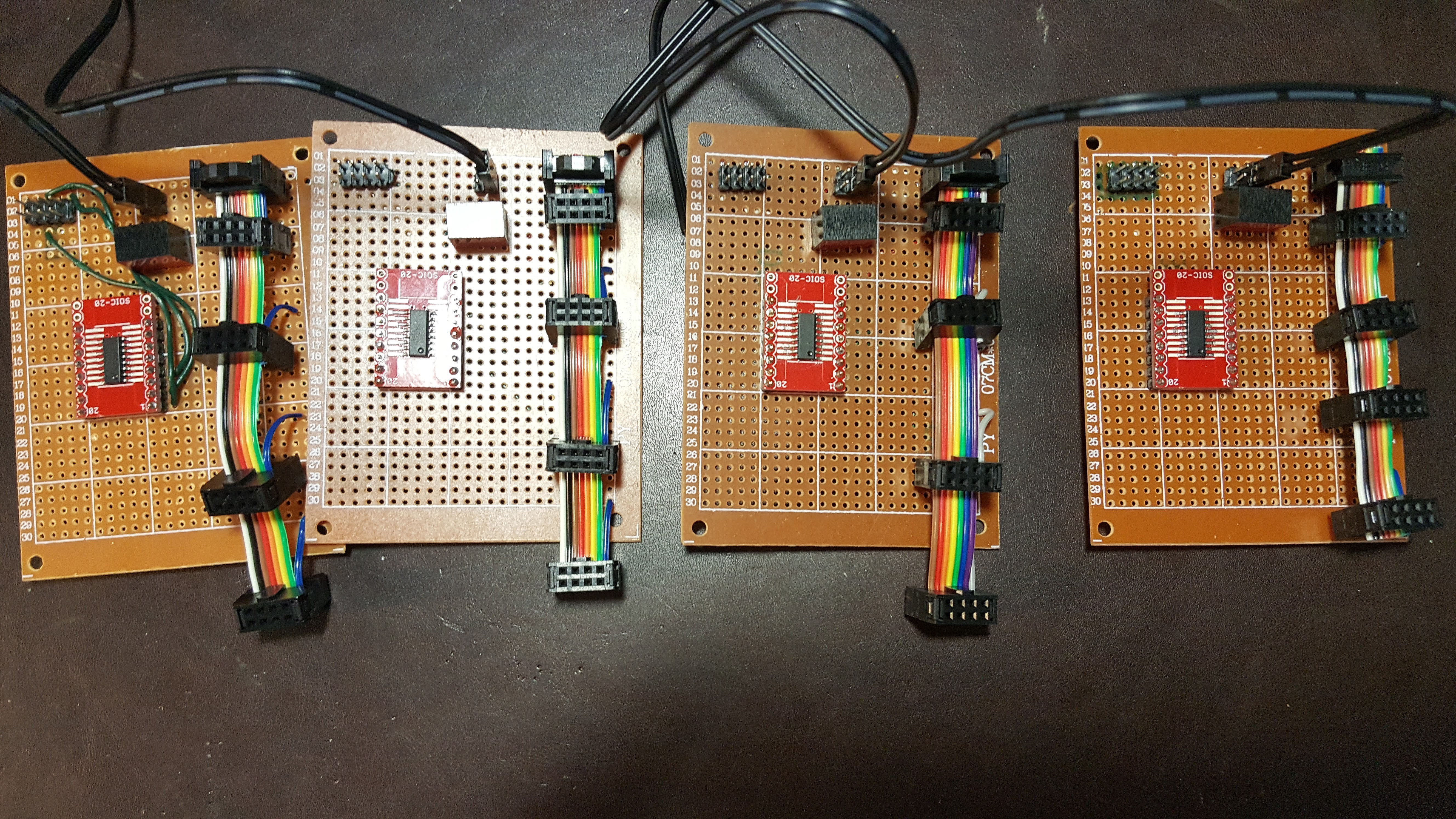
And finally, here’s all 4 bank controllers - I didn’t cable them all up with cameras because that doesn’t show any additional new information and it’s a giant pain in the ass, and the 4 cameras I did use were already busted and I really really really can’t afford to bust more cameras. It gets expensive :-)
![]()
Dear reader, if you have stuck with me thus far, allow me to thank you with two more details that others will just have to wait for. There’s been a lot of wrestling recently with CPU hardware and bandwidth issues as we amp up the cameras - the raw data rate in the system can easily exceed 500Mbps L The unavoidable conclusion is the power budget is going up because a bunch more SoCs are going to be coming to the party, and the battery weight is going way way up. So the mobility plans/constraints have been adjusted. This winter it is expected that the Quamera will move from the fixed robotic mast to a 2D mobile platform (think Roomba on steroids with eyeball from hell) and given it hasn’t either burnt down or knocked down my house, in Spring of 2018 it will move to a 3D mobile platform. Yup, first we build the house car, and then we build an autonomous flying drone. Daniel Suarez, this one’s for you!
-
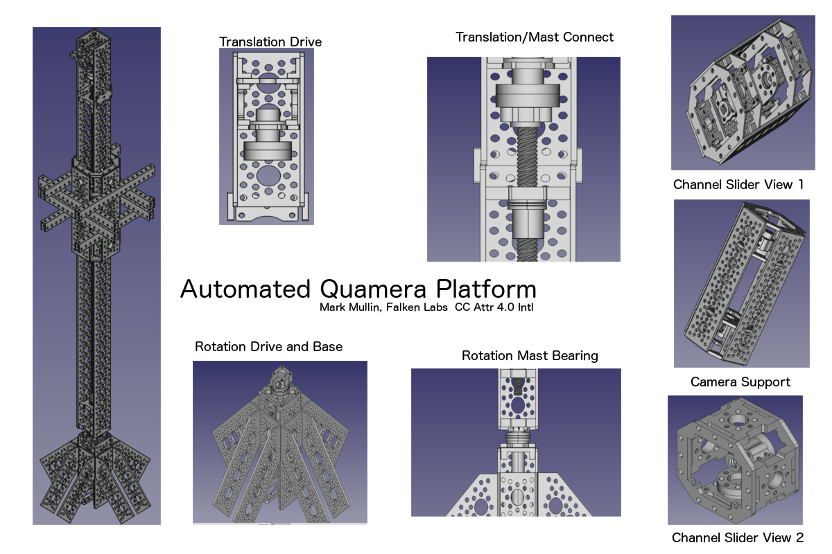
Automated Quamera Platform, Take 2
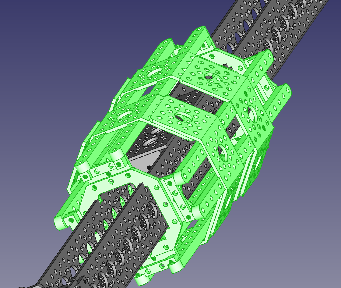
06/19/2017 at 01:03 • 0 commentsThe interesting thing about editors is that 30 minutes of work on their part nets you dozens of hours on your part. I had the good fortune to get some very useful advice from a tech at ServoCity on the original automated platform design, and well, that led to a lot of redesigning. Here's a picture of some of the new bits.
![]()
And another attempt at a writeup on the mast (I find mechanical engineering to be an effort of shepherding a horde of levers bent on self destruction) Links are to updated documents.
This is a robotic platform for a multi camera machine vision system to allow it to rapidly collect high resolution high quality RGB-Depth images in a spherical field of view. This platform helps test and calibrate algorithms that perform much of this work using basic trigonometry, before the results need to be handed of to more sophisticated machine vision systems. This supports the fundamental project hypothesis that mechanisms in insect vision, and lower level mechanisms in mammalian vision for image fusion and depth perception take place at a pre-cognitive level. A full writeup on the project is available here, a detailed BOM is available here, and here is a site that tracks the live status of the larger Quamera project.
-
Welcoming a valued new member of the team (who's always been there for me)
06/13/2017 at 02:00 • 0 commentsI'd like to take a quick moment to welcome Lee to the project. Lee has been a collaborator since I realized I needed to build my own rig. He is the brains behind the Arducam standardized image sensor interface, and I highly recommend his products. If you know your stuff, and you need imaging gear, Lee cannot be beaten. I threw a lot of products away to find him. Welcome Lee, I hope I do your cameras justice.
-
The hardware has a patronus :-)
06/11/2017 at 20:33 • 0 comments“I learned a long time ago that reality was much weirder than anyone's imagination.” Hunter S. Thompson
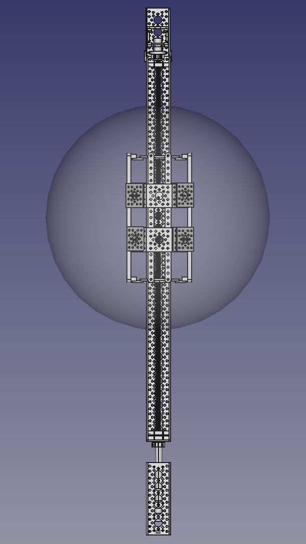
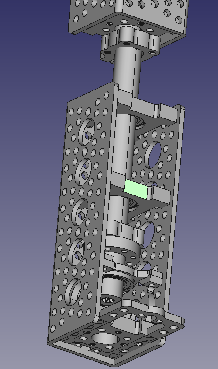
The last week was eaten by doing all of the engineering and CAD work to design the automated mast for the Quamera. When the Quamera is mounted on this mast with it’s almost full complement of 24 cameras (polar cameras had to give up their space for the mast) this allows the control systems to move the camera up and down and to spin it rapidly about this vertical axis. The entire body of materials involved in the construction of the mast is sourced from ServoCity and is based on their Actobotix components.
Here’s a drawing that gives you the context for the mast – the camera can move up and down on the mast, and the lower rotation drive can rotate the entire mast by 45° CCW or CW. These two steppers will be controlled by an Arduino, which will prove the basic motion tracking information and control surfaces to net driven logic on a controlling Beaglebone processor. The transparent bubble represents the volume occupied by the camera.
![]()
The most important bit is the spinning. In some of the previous pictures you can see the detected visual field overlap as false colors in the fused images - as the camera begins to oscillate back and forth by +-45° around the vertical axis, this allows it to capture accurate parallax error across it’s entire visual field, and that is what gives it what it needs for depth.
The ability of the camera to move up and down is not necessary per the hypothesis, however what math says is often ‘adjusted’ by engineering with comments along the line of ‘yeah, that’s nice but it ain’t never gonna happen’ :-) The information used in vertical travel will be used to determine whether in fact this information is necessary – it will also serve as a means for some of the first next generation math tests, when all of the cameras can rotate by something less than 45° on each axis (because optical zoom is coming ), and can perform these rotations off axis
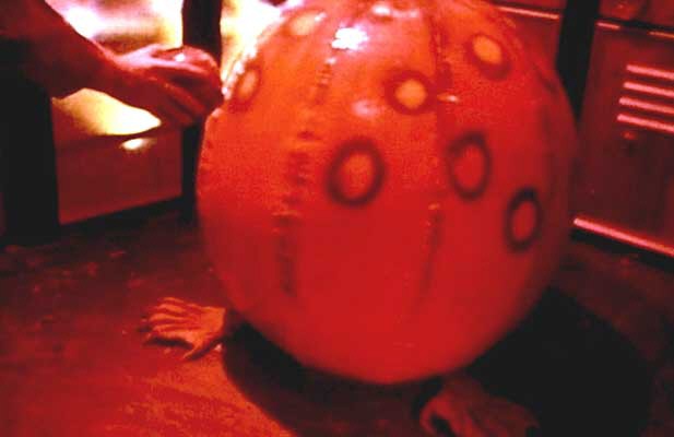
As a slight digression, now that it’s become mobile, I’ve successfully identified the Quamera’s corporeal patronus, namely this little fellow from the movie “Dark Star” There’s a lot of history here…..
![]()
Here’s some of the patronus in action
I used FreeCAD to do all the CAD work, and I’ve released all of the FreeCad files I generated under the Creative Commons Attribution 4.0 International license. You can get a much closer look at what’s going on by downloading FreeCAD if you don’t already have i - this will let you examine the 3D structure and any 2D engineering projections that strike your fancy. That said, the first place you want to go is to the Google Sheet shared here -- This will give you a high level map of the various subassemblies, a bill of materials, and a really sad workout of the torque needed to drive the system. From there, you can root around in here for all the stuff.
Am open to any commentary or help with this – I’m the first to admit that ME isn’t really my forte, I’m probably more of a menace than a solution……. But it’s a prototype/MVP, so the bars a little lower.
A few more pictures
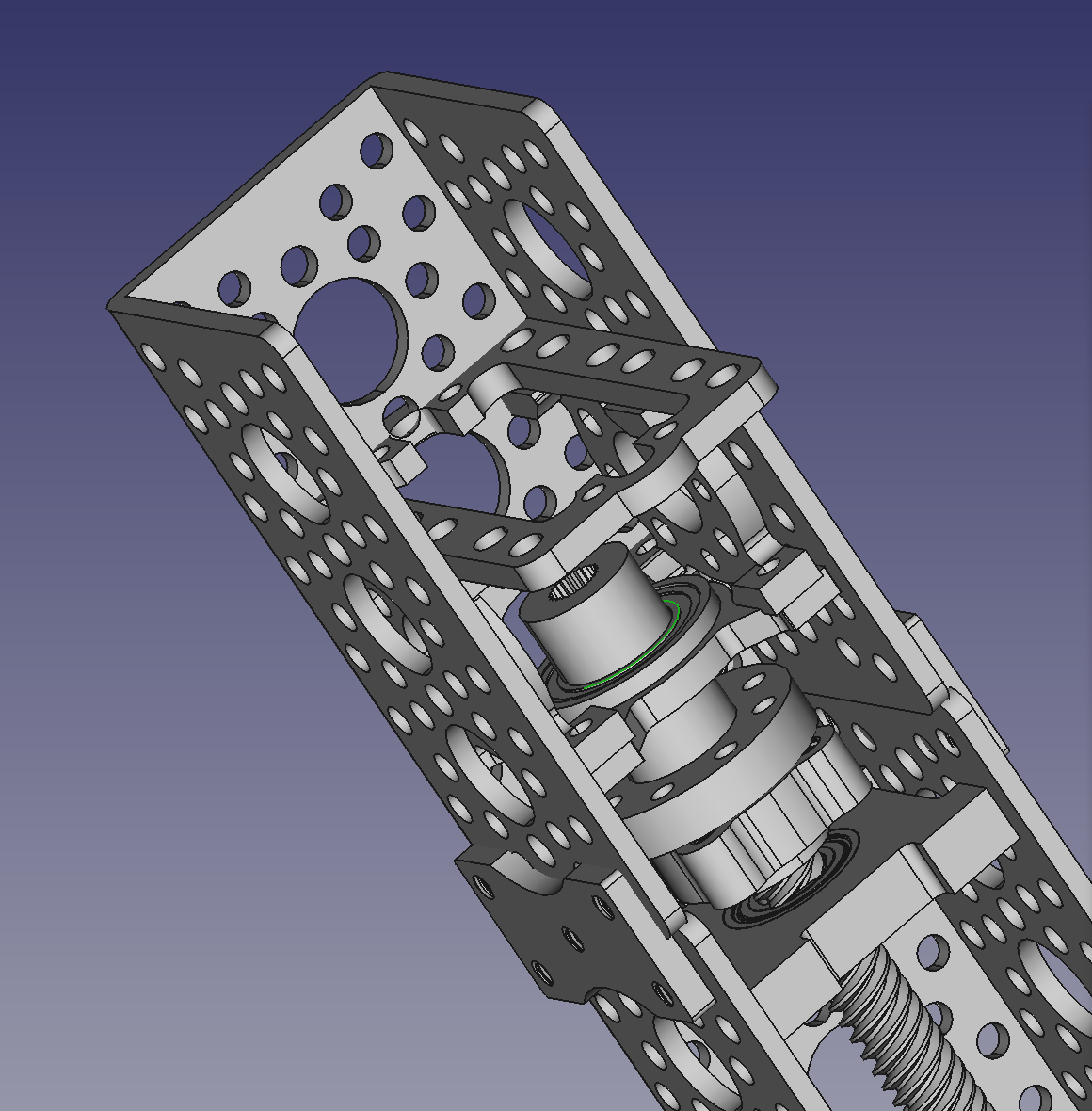
Here's the top vertical translation drive
![]()
This is the bottom rotation drive - poor thing has to spin mast, armature, and Quamera
![]()
and finally, a shot of the armature - you can see the drive plate and one of the nut plates on the screw at the center
![]()
Quamera Gen 2
Stereoscopic machine vision with integrated depth information