-
Website up and running
08/19/2014 at 23:35 • 0 commentsI have finally achieved simple functionality on the website. The whole project is hosted on my personal website, since I still have resources like databases available. The data is stored in a MySQL database which supports multiple users. There are a lot of features that I would like to have, but so far there are just a few things available: some diagnostics, user selection, simple error handling and most importantly a shopping list display. Apart from the user pages, there are a couple of others that will be accessed by the tags in order to change the status of the item or configure the tag. Here is how my list looks now, I have added just some random things:
The other functionality is to show the status of all the tags for a certain user. For now the information contained is the HW ID of the tag, status, battery status and when it was last changed by the tag or website
-
Panels are in!
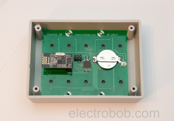
08/18/2014 at 23:05 • 0 commentsFirst panels are completed and can go online. Here are the first two assembled PCBs, one for development and one for actual usage in the kitchen.
As you can see, there is a lot of empty space in the box, but I will design the whole thing again for the next version, the panel should not be much thicker than a battery and PCB.
![DSC_2828]()
The buttons are designed to come out of the box surface just enough so that they can be pressed through the front plastic panel that comes over them.
And the first completed panel from the front which will take place in one of my cabinets in the kitchen. I have chosen the labels quite randomly, I almost never need flour, since I don’t cook.
![DSC_2832]()
-
Easy to assemble prototype
08/18/2014 at 23:04 • 0 commentsTo make the prototypes easier to fit in the box I have used a trick: I have placed a proper sized hole into the PCB under the buttons and the LEDs. That way I can install the PCB in the box and use it as a template to drill the holes. It takes less than 2 minutes for the whole 11 holes required for the 10 button panel, but I bet I could do it faster with enough practice.
-
Success!
08/17/2014 at 17:45 • 0 commentsThe first stockie tag(attached to serial port for debug) can now connect to the database and check the status of my coffee. This means that basic functionality in the tag software, gateway software and server side software is done, time to start building up on it. Here is the tag saying I am out of coffee(red led). It takes a lot of things to work together in order for this to happen, I had to develop software for the tag, the gateway(micro and router) and server while using C, bash, javascript, html, php and mysql and of course, everything has to work together.
And here is the tag saying I still have enough coffee(green led not that visible due to flash):
Some terminals for debugging: top is the tag data, middle is data going through the gateway microcontroller and at the bottom is the router
-
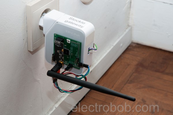
Gateway built
08/16/2014 at 21:36 • 0 commentsI have assembled the hardware of the gateway. The gateway is made from a TL-WR710N(EU) router and a Xmega header board I have previously designed. The XMEGA32A4U microcontroller serves as interface between the radio and the router since there is no hardware SPI available on the router. Currently the data transfer between the microcontroller and router is done with a USB-serial adapter because I need the original router serial port for debugging. Once the development is finished, I will switch to the router serial port. There is an additional serial connection between the microcontroller and PC to monitor the data transfers and debug.
The two antennas, router and NRF, are perpendicular to minimize coupling, as the router connects to my Wi-Fi to get online. Alternatively, I could use an Ethernet connection, but that requires an extra cable and limits the place where I can put the gateway.
![DSC_2788]()
![DSC_2791]()
![DSC_2794]()
![DSC_2801]()
I found a place for the gateway in a socket I never need to use.
![DSC_2807]()
Let the software development commence: two serial ports for debugging:
-
Schematics
08/13/2014 at 21:47 • 0 commentsSchematics
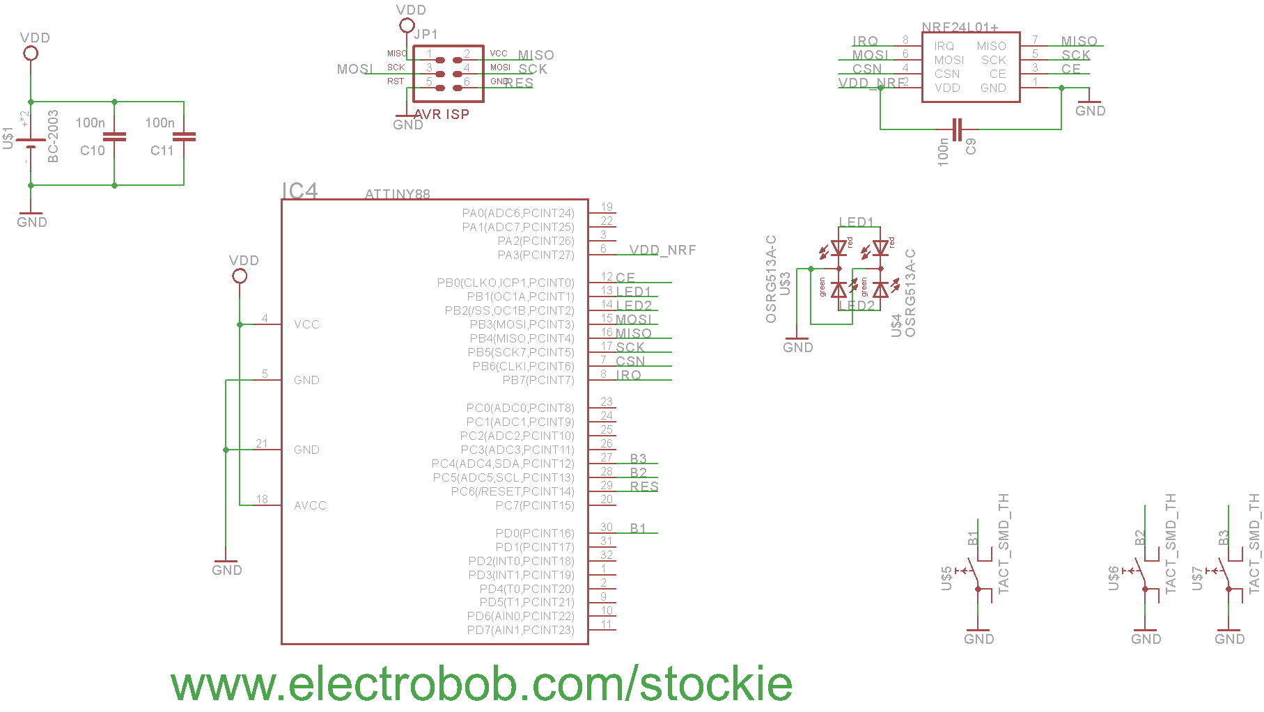
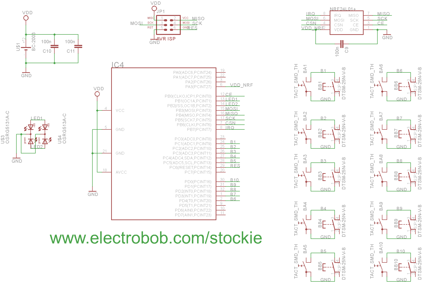
The design of the tags and panels is rather similar, they differ just in the number of buttons. The tags have up to 3 buttons while the first panels have up to 10. The parts list is kept to the minimum, I have even omitted the LED current limiting resistors because the reduced drive strength of the micro controller at 3V will keep the current within levels.
![]()
![]()
-
PCBs for the 10 button version arrived
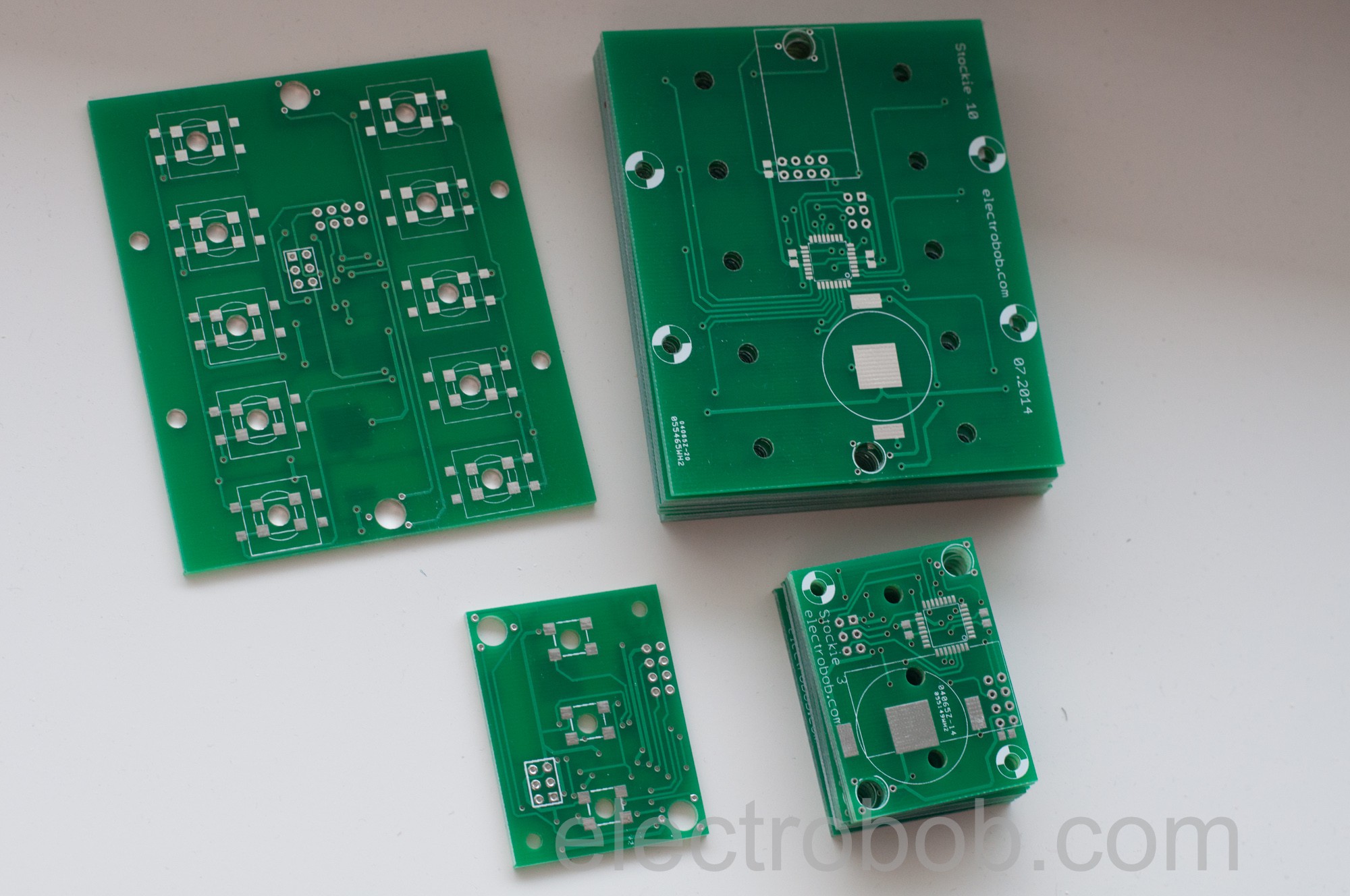
07/31/2014 at 18:24 • 0 comments![]()
-
Start talking
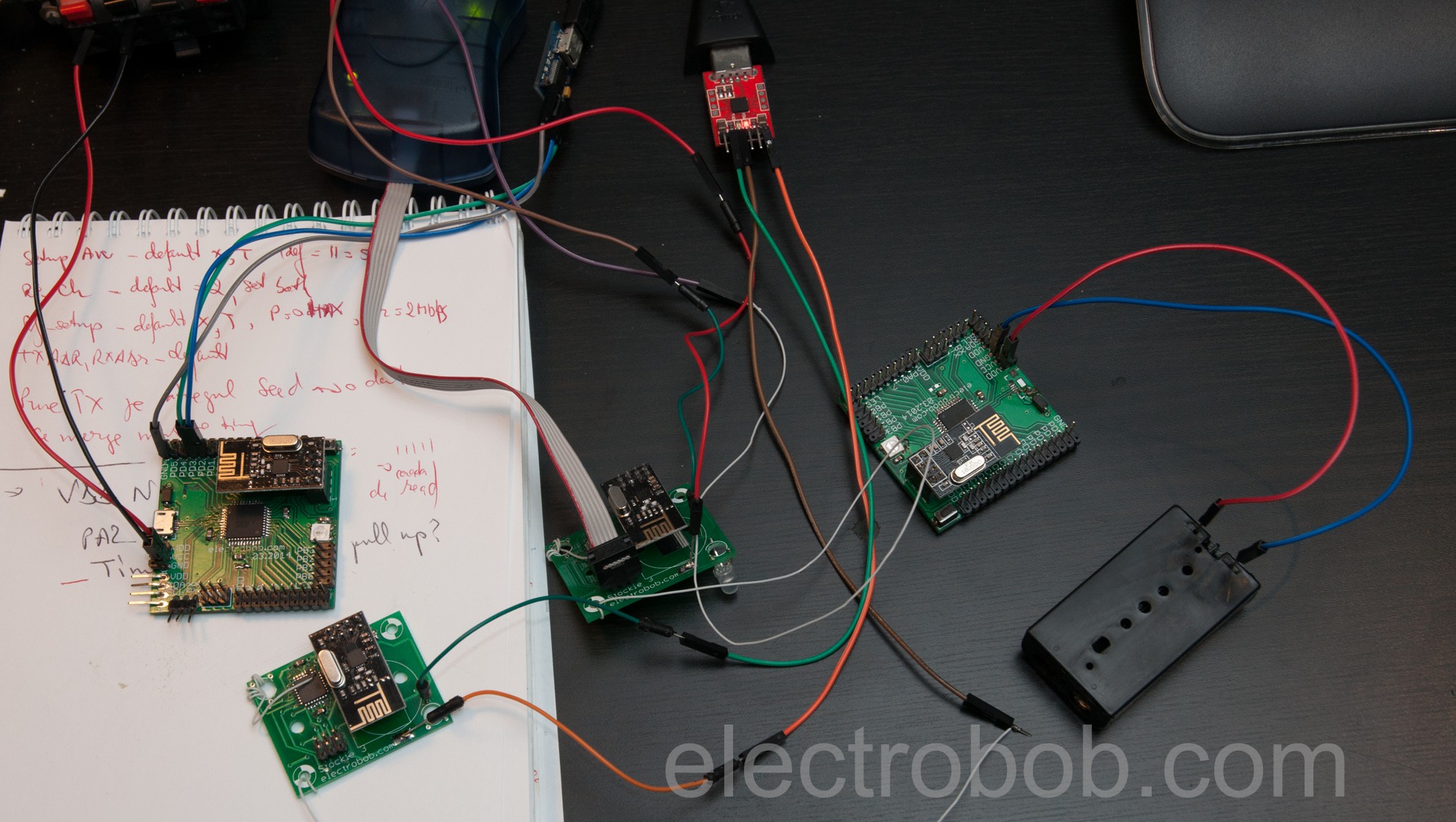
07/30/2014 at 21:49 • 0 commentsOne of the first steps of the built is to achieve communication between the stockie tags and the main node which will be the gateway to the server. The tags are based around an attiny88 microcontroller and a NRF24l01+ radio module. The gateway will use a router coupled with an XMEGA micro controller along with a NRF24L01+ high power module and external antenna (here shown with a regular one). In this combination the communication range is sufficient throughout the average house, powerful enough to pass through two floors.
![]()
Stockie - item centric shopping list
What if every time you run out of a product, the smart tag on it would instantly add it to your shopping list, at the touch of a button?
 electrobob