-
11. Print out main frame
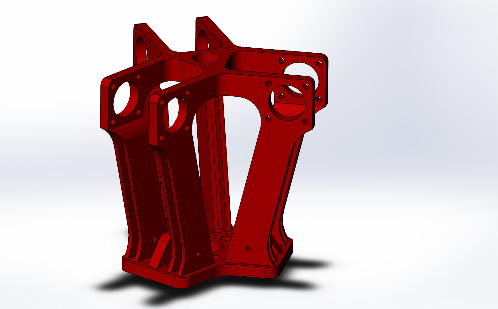
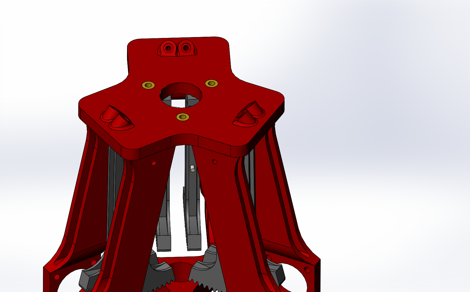
The main frame can be printed using a standard 3D filament printer, material choice is not critical.
-
22. Build up levers
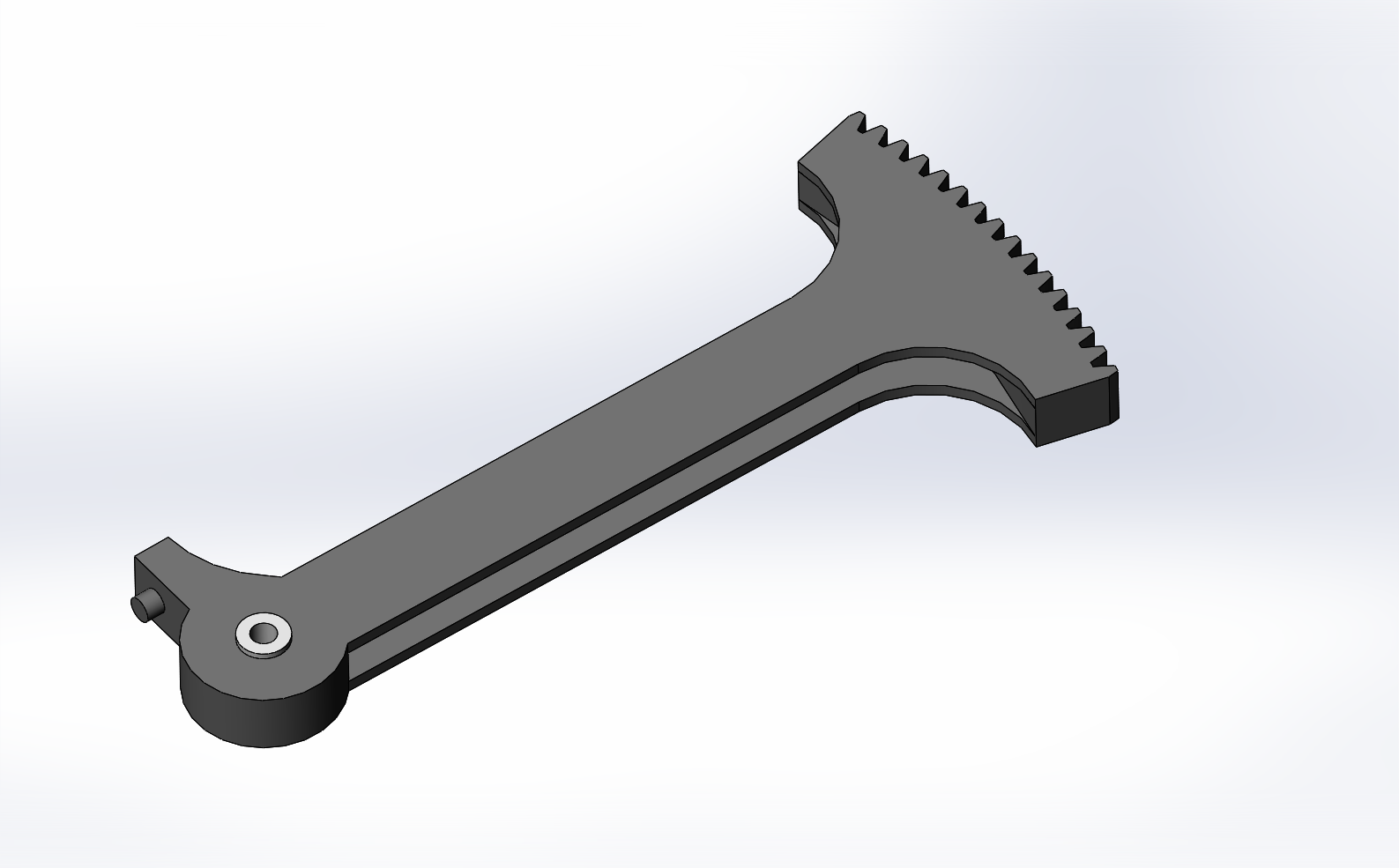
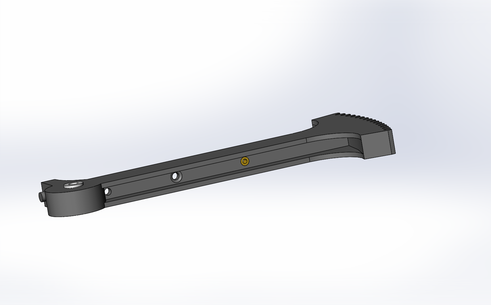
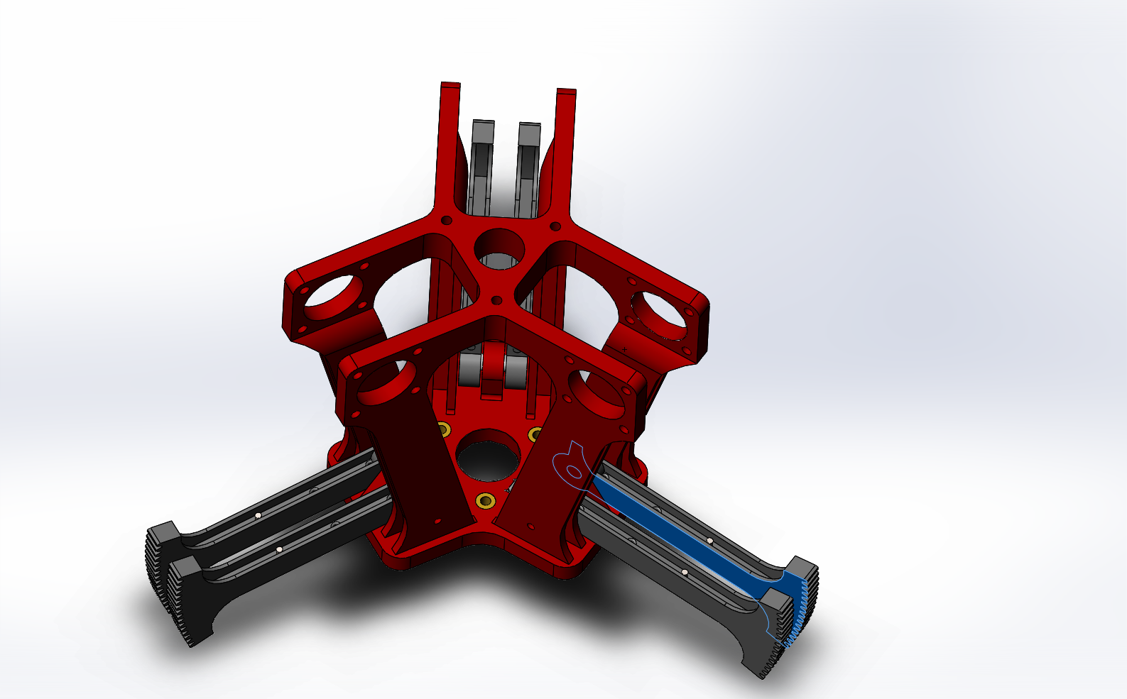
The levers and motor gears need to be printed using a high resolution method such as SLS nylon. This is because of the detail needed in the shape of the gear teeth (involute) that allows the set to move smoothly. Fit the PTFE bush into the pivot hole, make sure that the bush is slightly longer than the width of the lever. This helps keep the lever centered, and reduced friction from the sides of the frame whilst moving.
-
33. Fit brass insert
Fit the M1.2 brass threaded insert using a soldering iron, or carefully pressed in.
-
44. Fit locking screws
The wire securing screw can be fitted to the insert
-
55. Fit the levers to the frame
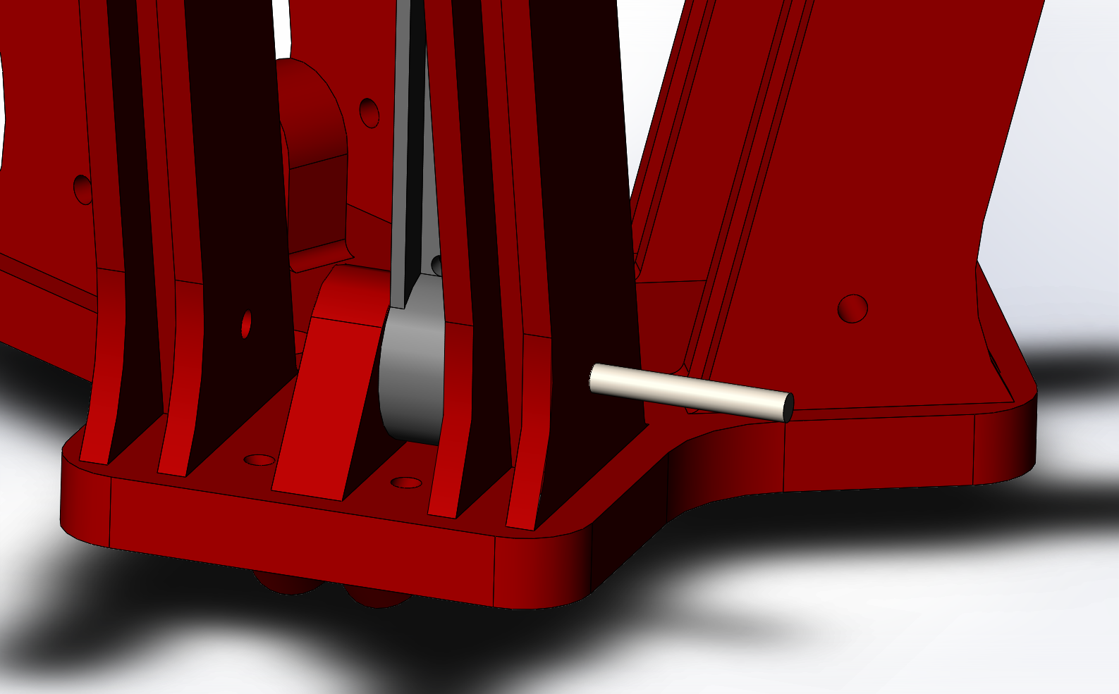
The levers are installed with the 'beak' at the bottom facing inward. The 2mm pin can be pushed in (you may need to drill / clear the pivot holes in the frame after printing)
-
66. Fit PCB inserts
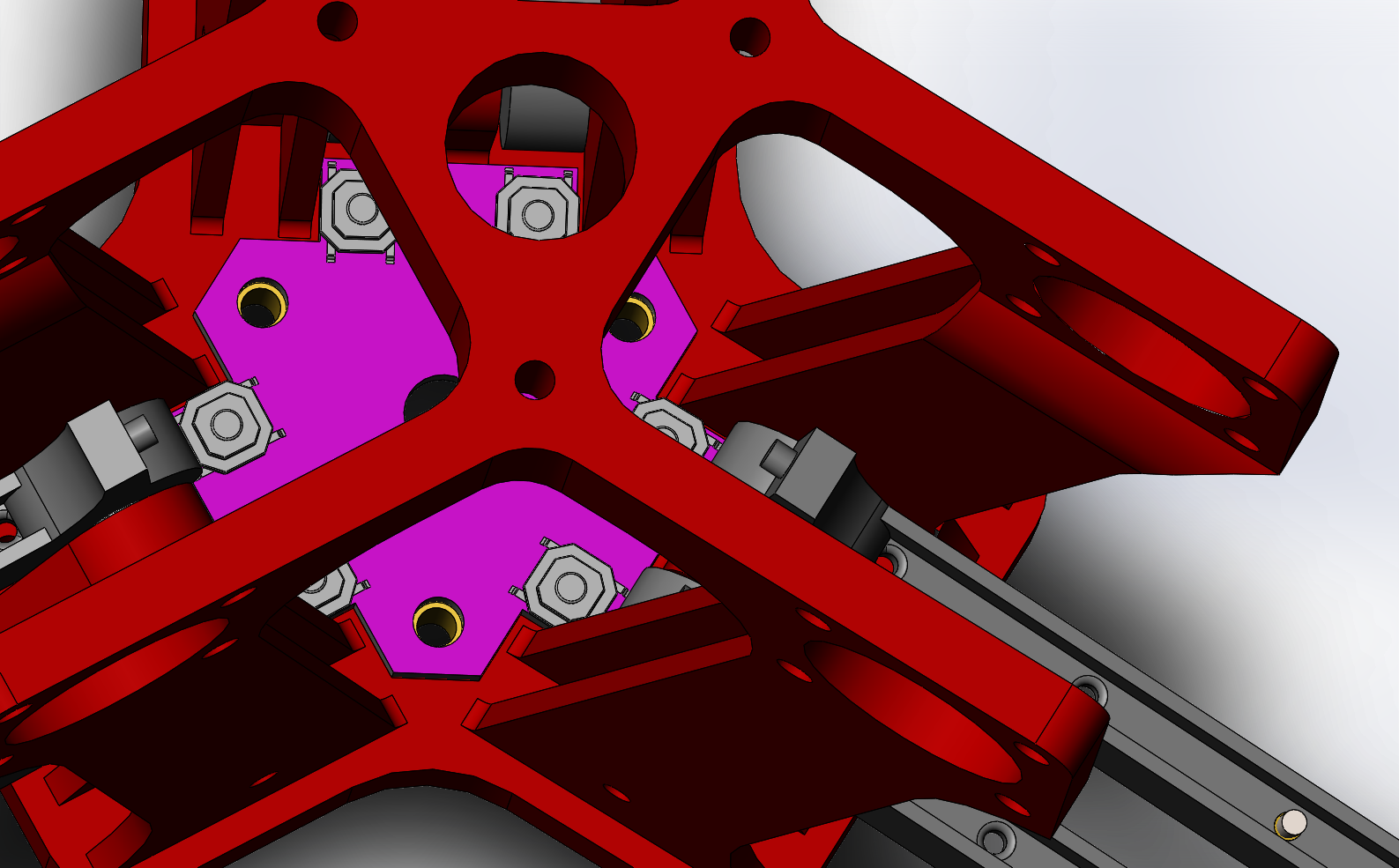
Using a soldering iron or careful pressure, fir the M3 brass threaded inserts that retain the PCB.
-
77. Assemble the PCB
Solder the tactile button switches to the PCB and either a 2x4 pin header or wires for the end stop connection. See the KiCad project file for the pinout and other details.
-
88. Clear access for PCB
Move the legs out to allow access for fitting the PCB to the frame.
-
99. Fit PCB
Use M3 screws to hold the PCB in place.
-
1010. Fit the motors
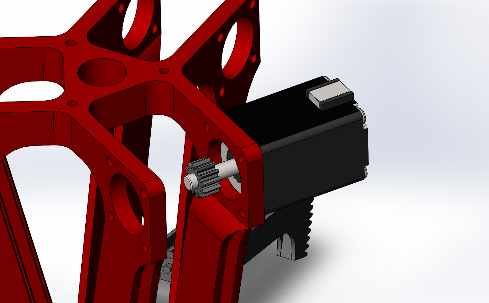
Fit the gears to the motors, depending on the particular motors that you have they may need adjustment. If the shafts are too long then they can be trimmed with an appropriate tool. similarly if they do not have a flat on the shaft, one can be carefully ground, or the gear model changed to suit. Thread lock will then been needed to hold the gear on the shaft. Fit the stepper motors using the M2 screws and if required nylon washers. Button hex works best as this allows the short end of a allen wrench to be used when fitting the opposing motors.
The motor mount holes have sufficient slack to allow the fit to be adjusted between the gear and the lever. The two need to be well engaged but still allow smooth movement. With the levers setup the stubs at the bottom of the levers can be trimmed (I used a needle file) so that when the buttons are pressed the end of the last lever gear tooth is in the middle of the motor gear. This is to maximise the distance that the lever can move.
6-Axis Micro Manipulator
Micron level manipulator, using printed and low cost components
 David Brown

Discussions
Become a Hackaday.io Member
Create an account to leave a comment. Already have an account? Log In.