-
A handful of prototypes
09/11/2017 at 08:39 • 0 commentsMaking prototypes
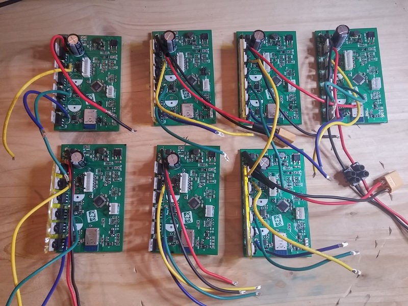
So far I have made a handful of prototypes for friends & family:
![]()
Doing them by hand is quite a lengthy process. The general workflow is
- applying solder paste to the PCB and placing the SMD components
- reflow soldering in oven
- first power up test slowly going from 0V-60V while checking that there are no shorts and all power converters are working correctly
- flashing the firmware and bootloader
- configuring the bluetooth LE
- soldering the THT components
- cutting the aluminium heat sink, drilling 6 holes and cutting the M3 threads
- applying the kapton tape and mounting the MOSFETs
- drilling a hole in the panel for the grommet
- mounting the whole board on a bike and doing a test ride
All in all it takes me well over three hours to make one controller by hand.
Currently I am looking into producing a batch with seeedstudio. The goal is to achieve a very competitive price tag of ~90$. This is about half the cost of what you currently have to pay for a cycle analyst and a controller while being a lot more powerful and lot less cabes.
Stay tuned for more updates....
-
So how far can you go? The 240km challenge.
09/10/2017 at 22:48 • 0 commentsThe question
The most asked question is always: "How far can you go with the battery?".
And the answer is: "It depends!".
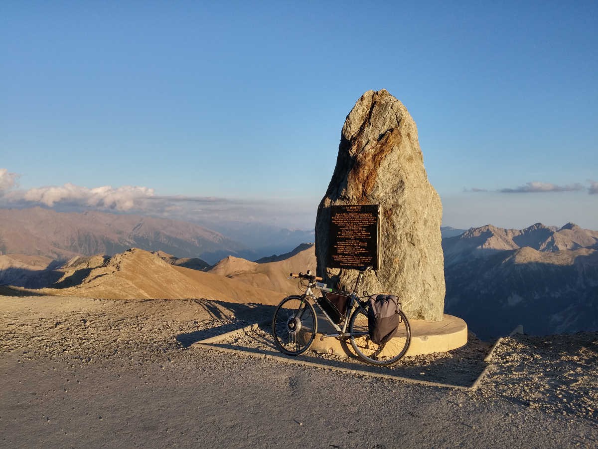
The challengeThe highest point that the Tour de France has ever passed is the Col de la Bonette at 2802 m (9192 ft).
The distance from Nice/France is 120 km thus back and forth is 240 km (150 miles). The challenge is to go up and back in one day with only one battery pack.
The tour
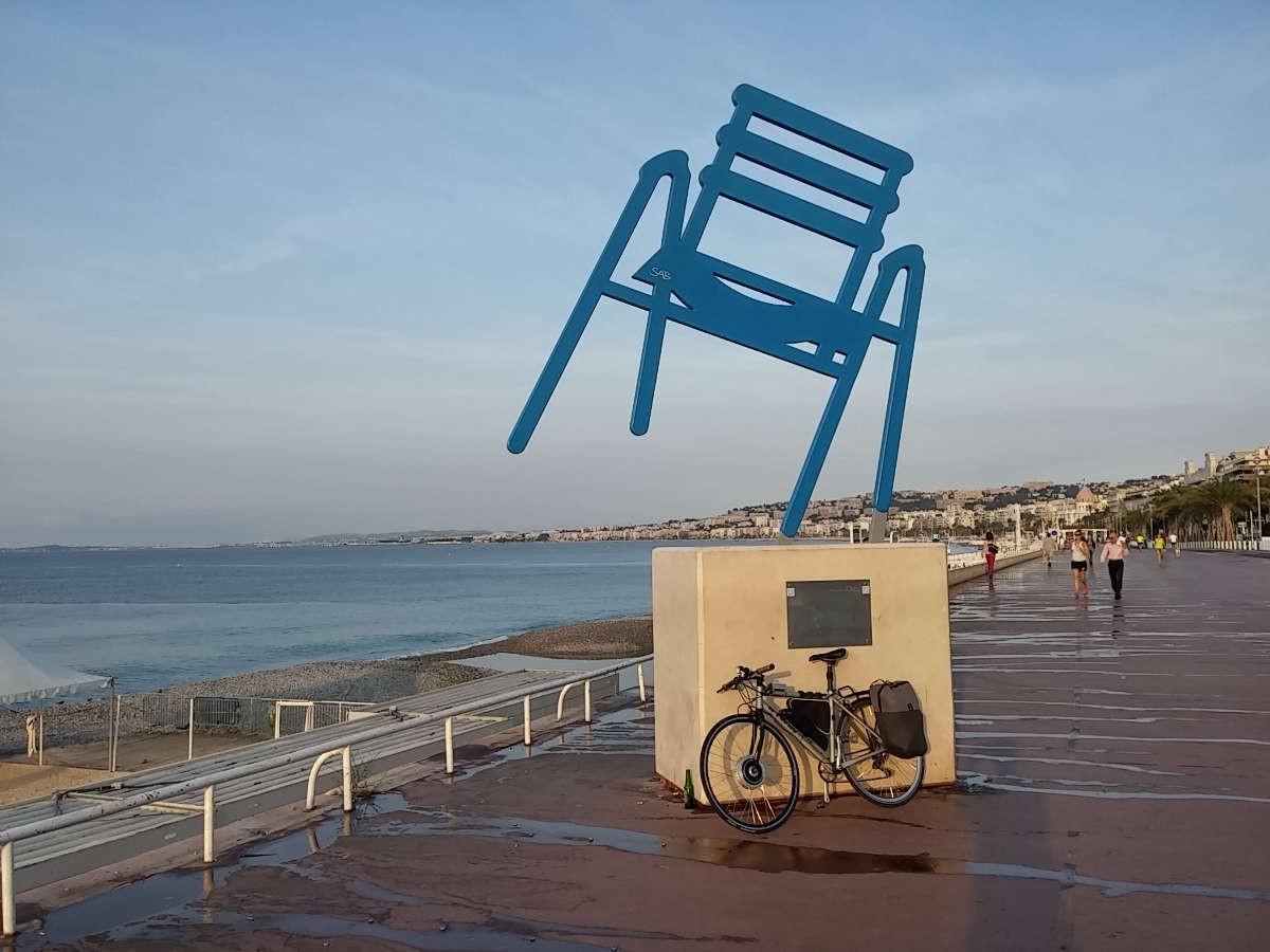
The start is in the early morning hours at the famous Promenade des Anglais in Nice.
![]()
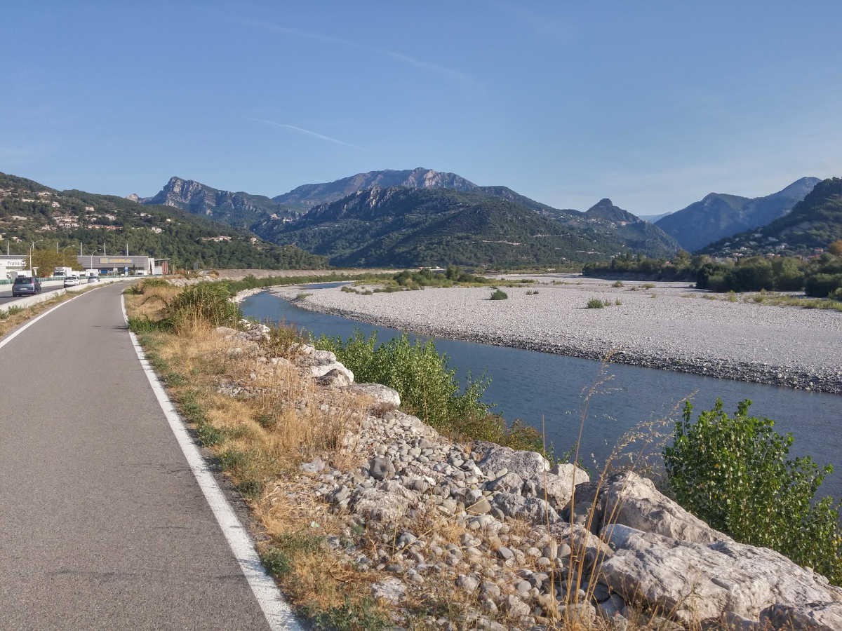
Under clear blue skies it goes along the Var river towards the mountains. In the morning there is always a bit of head wind due to typical offshore winds close to the sea.
![]()
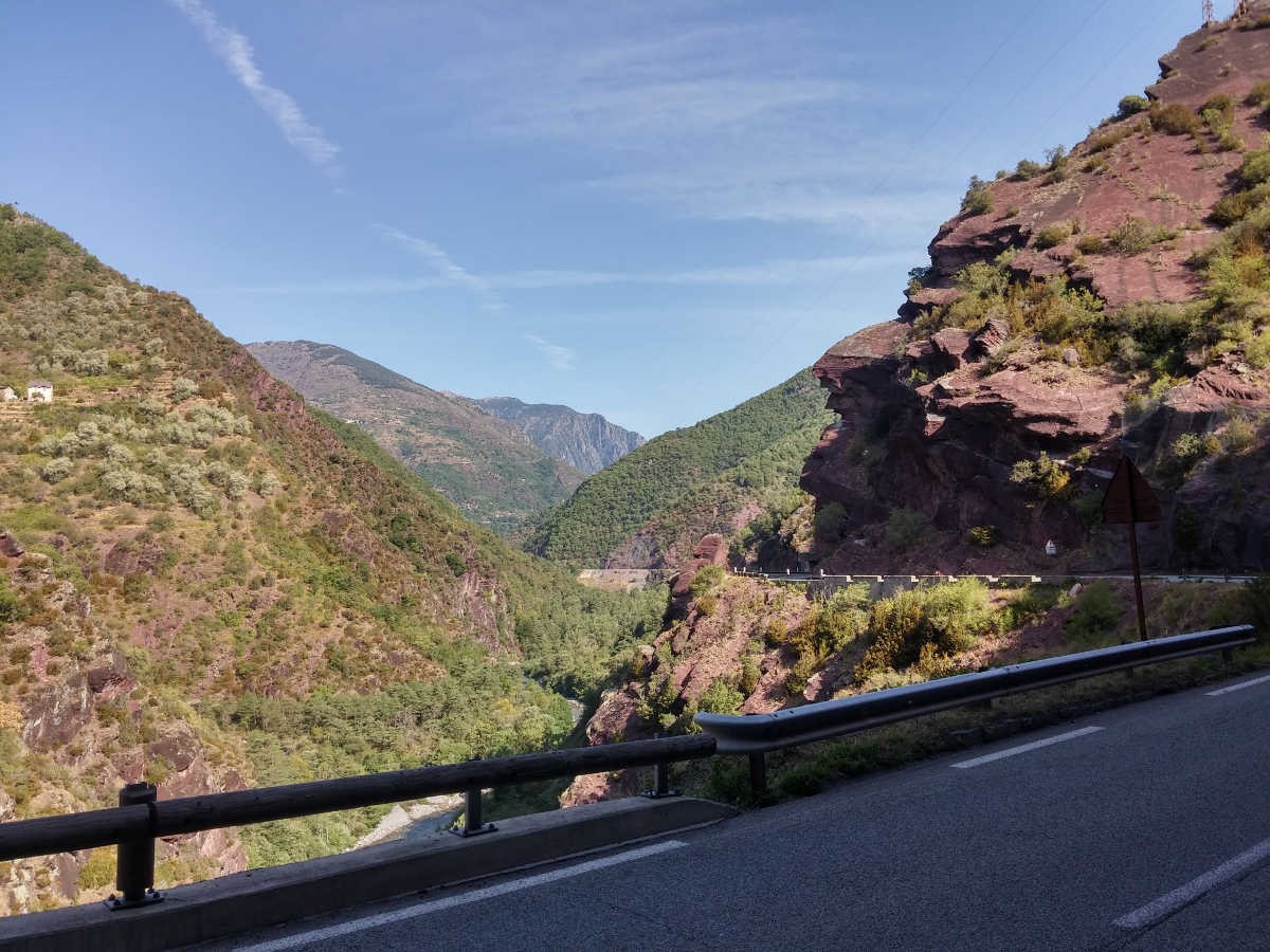
It is a very interesting landscape along the route which changes multiple times. A section in the middle is covered with red limestone.
![]()
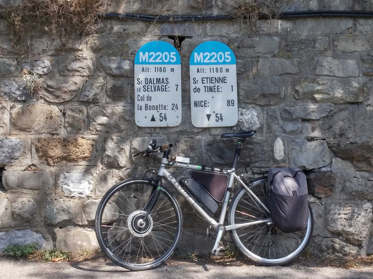
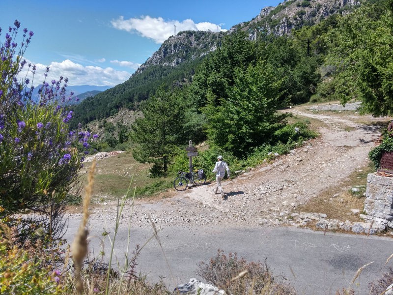
89 km after the start the real ascent begins.
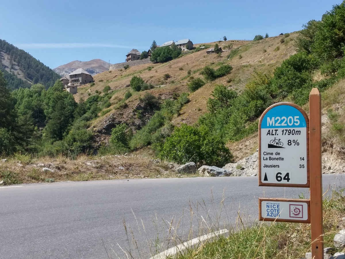
![]()
The peak in the background is the Col de la Bonette. Still 14km to go and 1000m of altitude to gain. It looked damn far away - and it was!
![]()
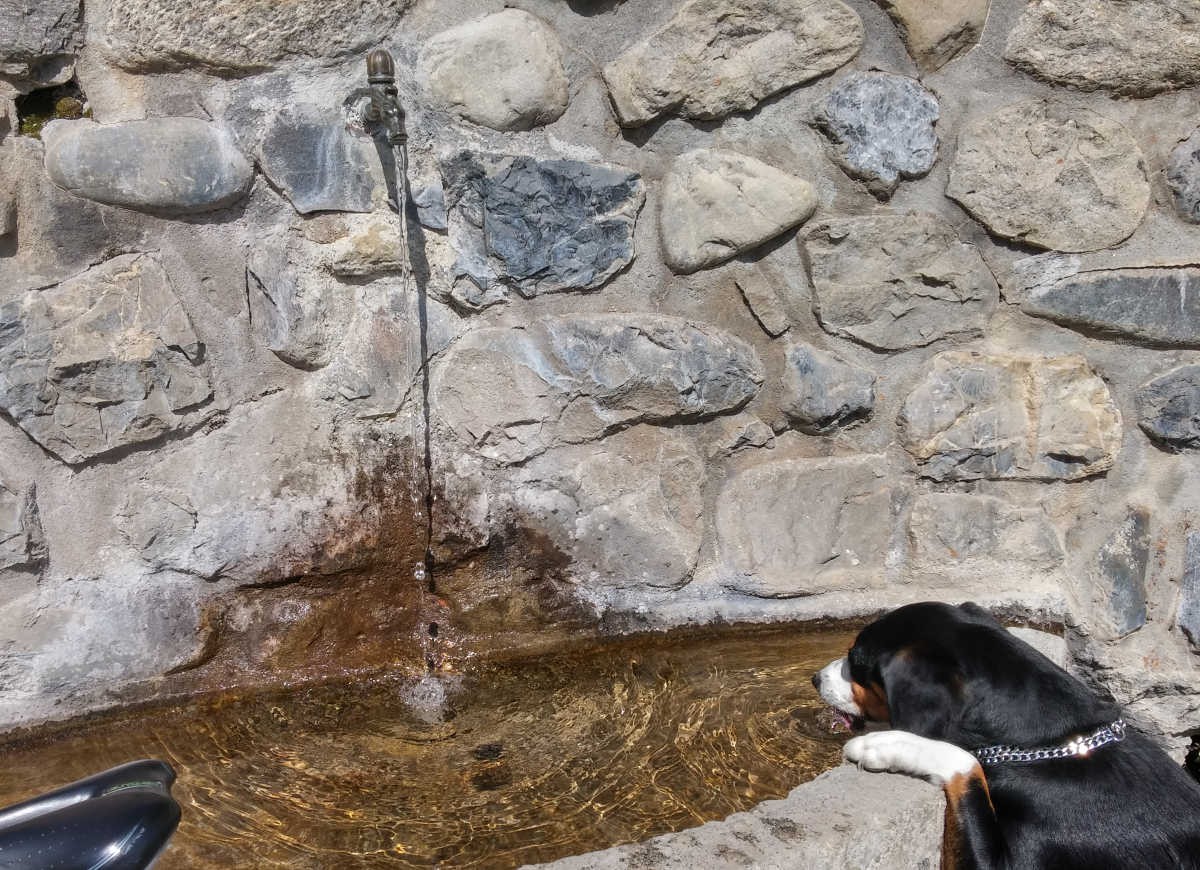
Last stop to refill the water supply
![]()
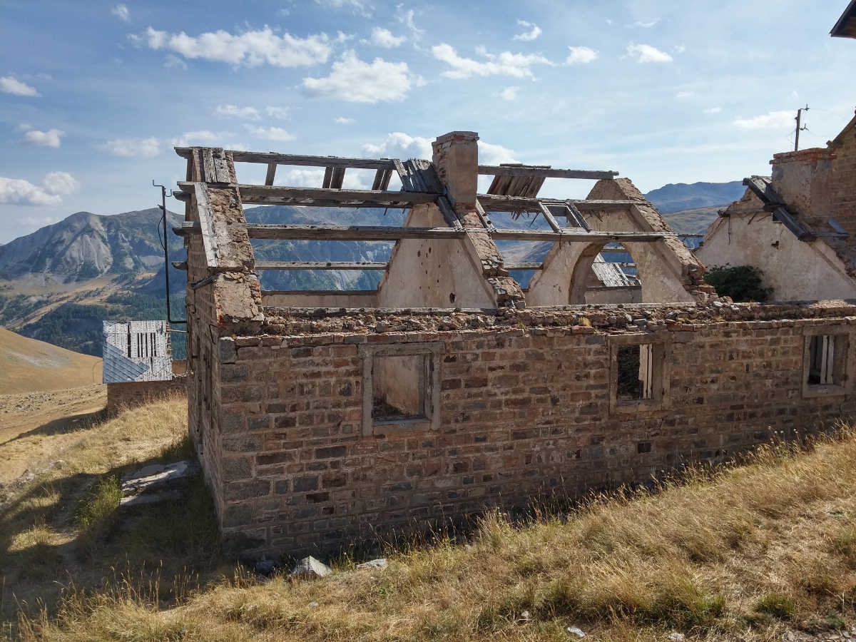
The difficult part starts roughly at 2500m - the thin air begins to effect the legs, every meter forward becomes a major effort. There is 40% less oxygen available than on sea level taking away your forces...
In the picture below is the "Camps des fourches", an old military village - and a veeery welcome stop to take some pictures.![]()
And finally the summit - mission accomplished!
Well almost, but the way back is all downhill ;)
![]()
Let's do some calculations
The battery on my bike is a medium sized battery with 48V and 11.6Ah giving roughly 550Wh of energy. Let's assume an average efficiency of the motor of 70% that gives us 385Wh of mechanical energy.
Let's assume the average speed is 24km/h (15mph) then we would need 10 hours for the trip.
The calculator on kreuzotter.de says we need 112W for 24km/h in the flat, thus in 10 hours we need 1.12 KWh for covering the distance.
For getting up to the top we need E = mgh -> 100kg * 9.81 * 2800m = 2746800Ws = 763Wh. Together this is a need of ~1.9KWh of energy, therefore the battery has supplied about 20% of the energy.
Conclusion: obviously eBikes keep you fit!
The maps
Ascent
http://cyclehikemap.eu/mymaps/view.php?id=73
http://cyclehikemap.eu/mymaps/view.php?id=72
http://cyclehikemap.eu/mymaps/view.php?id=71Retour
http://cyclehikemap.eu/mymaps/view.php?id=70
Food
5 bananas
2 baguettes with mountain cheese, ham, tomatoes and olive oil
plenty of waterFun
Priceless!
-
Unobtainium - findchips.com
07/24/2017 at 13:59 • 5 commentsI have been a bit slow on updating the logs. Unfortunately there is a reason out of my control: the ATMEGA328PB has become unobtainium und thus making another prototype has become impossible.
All this despite the fantastic findchips.com. Findchips is agreat service for managing your BOMs and finding the right places to source them.
Nevertheless, they are nowhere to find anymore, not even on obscure websites and much less so official distributors.
If anybody has a good channel to Microchips - who are also sponsors of the hackaday prize - maybe you can ask them to look in some drawer for some left over ICs.... I'd be more than grateful to get a handful of them!
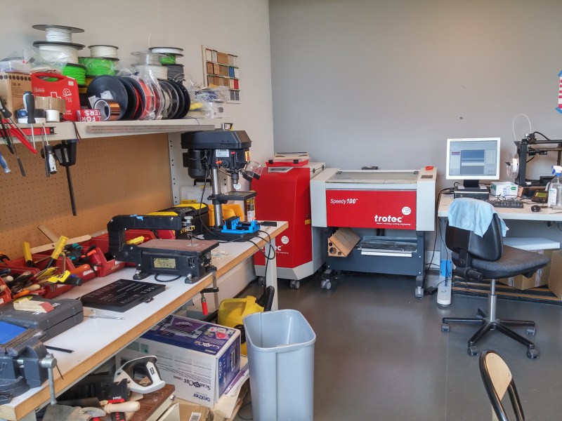
Meanwhile I have been polishing the enclosure with some laser cut panels. Below is a picture of the local fab lab SOFAB:
![]()
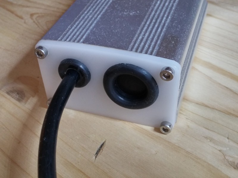
And this is what the result looks like:
![]()
-
Doping test - PASS || KERS - PASS
07/24/2017 at 13:52 • 0 commentsDoping Test
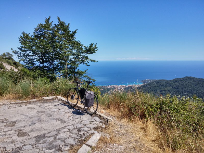
Given enough Watts, all mountains become shallow. As I live on the french riviera, the obvious place to test an ebike ist the Col de la Madonne. It is pretty famous among road cyclists because it was the favourite test drive for Lance Armstrong.
And guys, it is beautiful. Say about Lance what you want, be he knew the good places.
This is what it looks like:
![]()
All the way up you have a stunning view over the mediterranean and very little road traffic. The glamour of Monaco is at your feet, the blue of the sky melts into the blue of the sea...
The picture below is taken at the top of the pass, a selfie taken the old fashioned way with a timer. I think I need to train this a bit more.
![]()
KERS - Kinetic Energy Recovery System
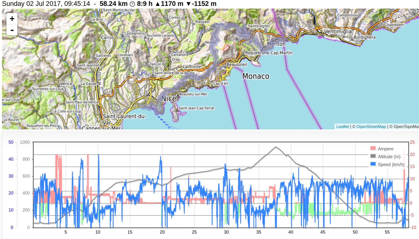
Below is the log of the trip from Nice to Italy via the Col de la Madonne. In true geek fashion the controller is logging all the data. Display in the chart is:
- blue: speed in km/h
- gray: altitude profile in m
- red: ampere of the motor @ 48V
- green: Kinetic Energy Recovery System = recharge the battery
![]()
The green part is actually the cool part, the controller can does regenerative braking, in Formula 1 better known as KERS.
Thus doing the long descent is the ultimate stress test for the controller. PASS!
-
eBike basics
06/12/2017 at 09:18 • 0 commentsThere are plenty of instructables on youtube videos out there about how to convert a bicycle into an eBike. I wont repeat this here but just cover the basics.
What you need
- motor (($50-$500)
- battery (($100-$1000)
- controller ($40-$200)
- throttle, pedal sensor, speed sensor, brake lever with sensor
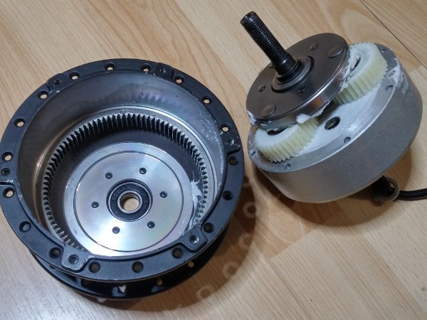
Motor
The easiest conversion is done with a hub motor. They come in two varieties: as direct drive motor which is gearless and as geared motors. Here is a picture of a geared hub motor:
![]()
You can use a 36V motor also on 48V and even higher. It is not the volts that destroy a motor but the amps. Technically a motor is nothing but a copper wire. When too many amps are pushed through for too long then the insulation of the wires will melt causing short circuits and subsequently havoc. Also the magnets will loose their force once being heated over the curie temperature.
Battery
There are plenty out there and the more capacity you want the more expensive it will be. To calculate how much battery you need there is a calculator here. As a rule of thumb 100W of assistance will give you already a nice boost. Thus with a battery of 500Wh you can have five hours of 100W of assist. That's good for cruising on the flat at 25km/h or 16mph. However when going uphill fast you may need 1000W and your battery will last only 30 minutes.
In general if you continue to use the bicycle as such and use the motor only as assist then a small battery can bring you pretty far. If you want to use the bicycle as an electric motorcycle then you will need many more times of battery.
Controller
The controller must fit the battery voltage. A battery voltage too high will destroy it. A battery voltage too low and the controller will cut off believing the battery is empty.
-
Current project status
06/12/2017 at 08:39 • 1 commentController hardware
After several revision the hardware is working really well and has been tested for several thousand kilometers now. A mini series of five pieces has been produced to check the DFM.
Controller firmware
The controller firmware is mostly finished but still has some hardwired lines in it. A few minor things are still on the list for example soft fade out of assist when reaching the speed limit. Time needed: a few dozen hours.
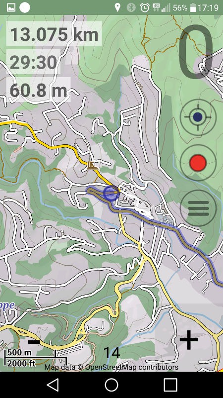
Android app
Not yet on the market. Needs to be published. However there is a sister app for offline map usage with openstreetmap which has its first beta on the market. If you want to give it already a test run, you can find it here.
A screenshot of the app:
![]()
Website
Only the very basics but upload and display of tracks from the app are working. See an example track.
-
PCB production in pictures
06/10/2017 at 22:31 • 0 commentsHere are some pictures of the various steps of the PCB production. My -not exactly cheap- european fab house sends them per email which shortens nicely the waiting time until the PCBs finally arrive.
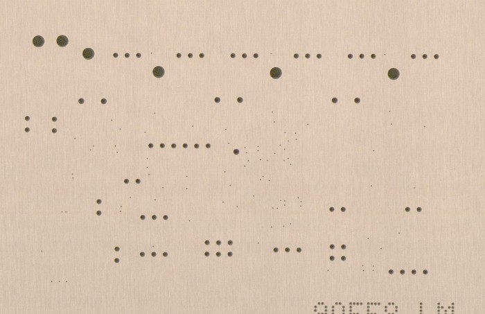
The first step is drilling the holes for THT components and for the vias. It's more than 150 of them!
![]()
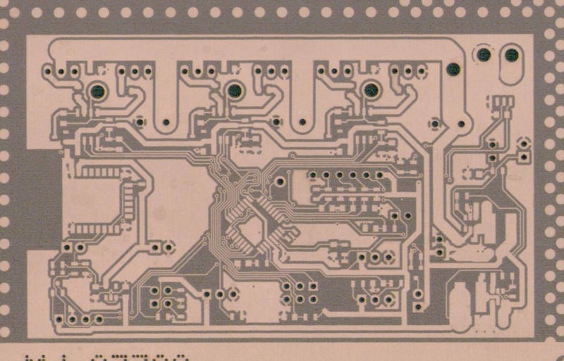
The next step is applying the photo mask and etching. You can already see very well the structure of all the traces.
![]()
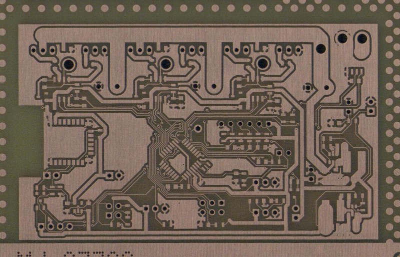
And this is what the board looks like right after the etching:
![]()
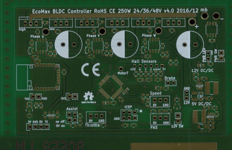
The final steps are then to apply the solder mask and the silk screen and to finish the pads with ENIG gold plating:
![]()
That's it, almost ready. The final steps are cutting and shipping. Pictures of the assembly will follow...
-
Pin assignments microcontroller
06/10/2017 at 11:01 • 0 commentsAssigning the pins is quite a puzzle. We have digital pins and analog pins, pins that need to do PWM and pins that need to do serial output. Other pins need to be connected to interrupts. Thus we need to juggle assignments until everything fits.
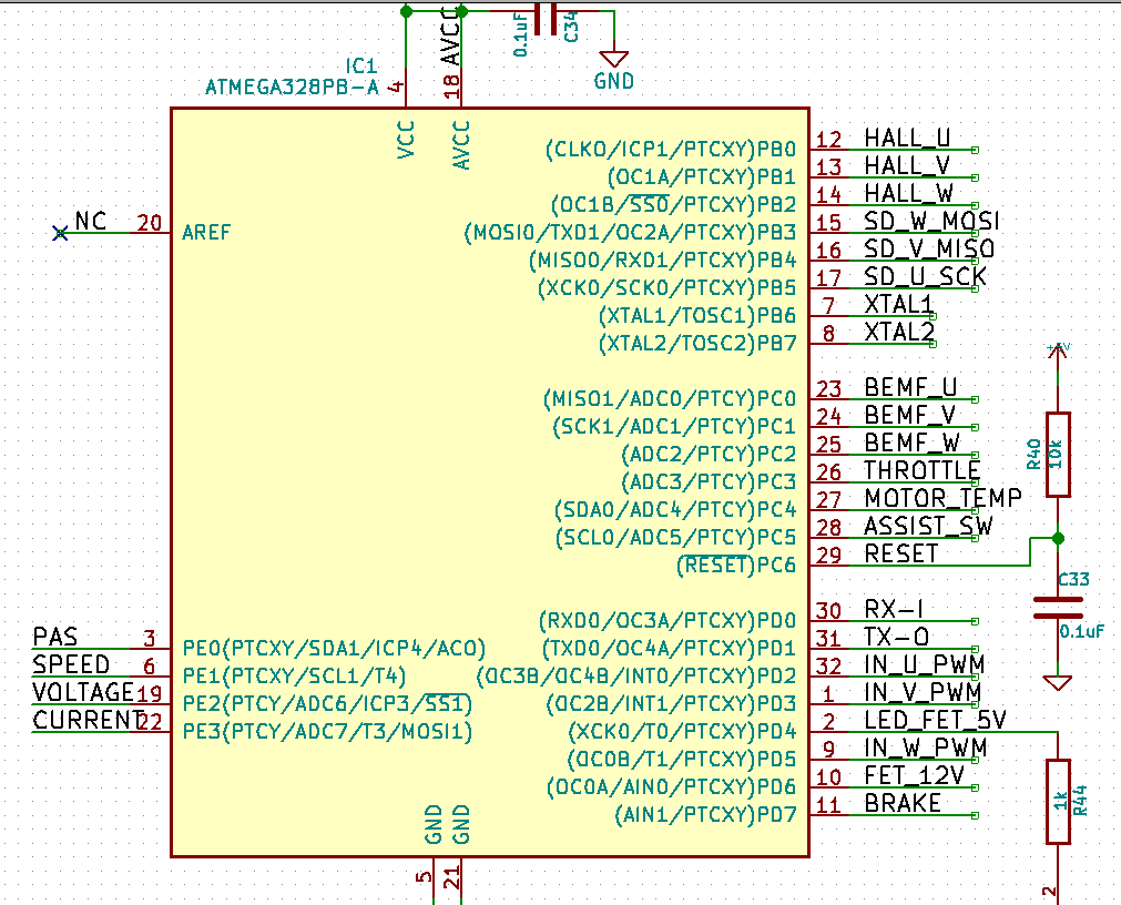
The pin assignment on the controller looks like this:
![]()
First consideration are the PWM pins for driving the half bridges. This could either be the OCxA or the OCxB pins. The OCxB pins allow for a more flexible configuration thus we'll use PD2, PD3 and PD5. Next we assign the hall sensor pins. These are digital and should be next to each other and more importantly they need to be on the same port to generate the same interrupt. PB0 to PB2 is the good choice. Next we assign the 3 shut down pins for the half bridges. For ease of programming they should be next to each other and on the same port. PB3 to PB5 are free and fit these conditions. Also fixed are the serial pins for the communication with the bluetooth chip. Thus PD0 and PD1 are used as RX and TX lines.
Pins needing analog input are the BEMF pins. These are for voltage sensing on the phases and can be used for sensorless operation. Then obviously the throttle, the voltage and current sensing and motor temperature. Last not least we use an analog pin for a three button switch together with a resistor network.
Further inputs are brake, speed and pedal sensors. They are all digital inputs with no specific requirements.
This leaves us with two pins of which we'll use one for a blinkenlight LED and the other to switch a small MOSFET for the bike light or for a brake light.
-
Basic board layout
06/10/2017 at 09:35 • 0 commentsAfter the decision for the microcontroller is done we need to make decisions for the basic board layout. This also includes the choice of housing for the MOSFETs. The basic choice here is whether to use SMD fets or THT fets. As we want to run up to 1000W through the board the choice of THT is more sensible and TO-220 is a good form factor with a large choice of products.
Let's do a quick back-of-the-envelope calculation. We have 50Volt from the battery and we want 1000W output. Thus we have at least 20A going through the fets. However, the controller acts together with the inductance of the motor as a DC/DC converter and the amperage can thus be even higher unless being limited by the firmware.
So we'll assume 50% margin which results in 30A. The on-resistance of a reasonable MOSFET is around 5mOhm. Thus we have 30A*30A*0.005Ohm = 4.5W. As a rule of thumb a TO-220 can dissipate roughly 1 Watt when not mounted on a heat sink. Thus at 1000W we need to properly mount them on the enclosure.
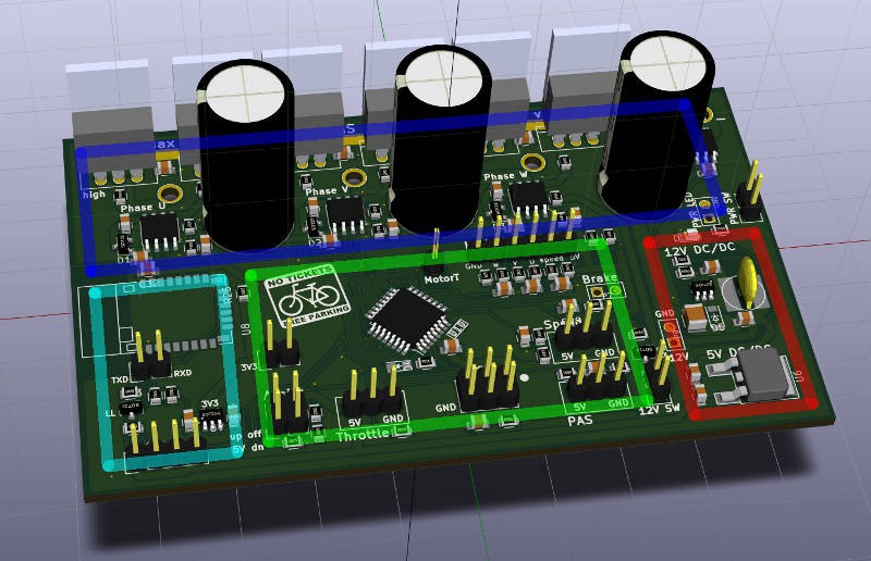
Here is a picture of the general layout in a 3D rendering from KiCAD:
![]()
The board measures 100x60mm. The board is properly designed into sections. The dark blue part is the power stage. The power stage contains the 6 MOSFETs, the 3 half bridge drivers with boot strap circuitry and the caps.
The green part is the brain with the uC and various I/O connectors for throttle, hall sensors, brake, speed sensor, pedal sensor and ICSP.
On the right side in red there are the power regulators. The top one converts the 50V from the battery to 12V for driving the fets. It has 0.6A output thus can produce up to 7.2W. The board itself needs about 1W so we have 5W left for LED lights on the bicycle. Below is the old classic 7805 linear regulator for powering the brain.
Finally we have on the lower left the bluetooth section. This contains another voltage regulator for 3.3V and a logic level converter for the 5V TTL to 3.3V TTL.
That's it, stay tuned for the next diary entry!
-
Design decisions - OMG Arduino
06/09/2017 at 19:31 • 0 commentsChoice of microcontroller
First and foremost the decision of the microcontroller had to be made. While there are dedicated chips available, I like to code embedded systems and thus the whole control should be done in firmware. The following GPIOs are needed:
- 6 digital ports with hardware PWM for the 6 MOSFETs
- 3 digital ports for hall sensors in the motor for position sensing
- 3 analog ports for phase sensing for sensorless operation
- 3 digital port for brake switch, pedal sensor and speed sensor
- 3 analog ports for throttle, assist mode and thermal motor sensor
- 2 digital ports for light switching
- 2 analog ports for sensing battery voltage and current
It so happens that this fits onto an Atmega328PB. The 328PB has the advantage of having 5 timers versus 3 timers on the 328P on the Arduino boards. This is a nice convenience as 3 timers can be used for the PWM generation, while still having two more timers left for general timing purposes.
Why 8-bit and not 32-bit ARM core? The idea behind this choice is a bit hacker ethics - you can still fully understand what is happening under the hood of an 8-bit chip and the datasheet is only 400 pages. In order to program the 32 bit chips you wont easily do it without using boiler plate code produced automatically by Atmel Studio. So it is a minimalist approach. Or as Antoine de Saint-Exupery put it: “Perfection is achieved, not when there is nothing more to add, but when there is nothing left to take away.”
What else is needed?
The input voltage needs to cover up to 13s lipo batteries. 13s means 13 cells in series which adds up to 54.6 Volt when fully charged. These battery packs are usually sold as 48V packs and are a common standard. The controller itself needs 10-12V for driving the MOSFETs and 5V for the microcontroller.
Coming down from 55V to 12V is best done with a switching regulator. This gives also enough output power to connect a normal bicycle light. The second stage 12V to 5V is done with a linear regulator as the microcontroller and the bluetooth only need a few dozen mW of power.
Power stage
The MOSFETs gates cannot be powered directly from the uC ports for two reasons: the gates need at least 10V to fully switch on and you need to switch them on and off very fast to minimize switching losses. Very fast means in the order of 100ns. There are plenty of dedicated chips out there and I choose the International Rectifier IR2104 half bridge driver for this purpose. The chip offers shoot-through protection, i.e. high and low side MOSFET will never both be switched on at the same time. This is nice to have because "shoot through" means a battery short circuit and therefore the release of magic smoke with a loud bang.
The chip also has a bootstrap circuitry thus N-channel MOSFETs can also be used for the high side.
That's it, those are the main components of the BLDC controller.
Next up: board layout overview, coming tomorrow.
Smart BLDC controller for eBikes with BLE
A smart, hackable BLDC controller for electric bicycles with bluetooth, Android app and a web service using an Atmega328