Timo Birnschein
-
Milling your first PCB
06/22/2017 at 04:02 • 1 commentMilling a PCB:
You have come this far, that is both admirable and awesome and I thank you for following along!
But that also means you need to get the settings and instructions now to be able to mill your first PCB successfully. In other words, this log entry might become a little wordy but I will try to keep it as short as possible since I'm not a fan of reading 20 pages to get the bottom of a simple step myself.
- Fire up eagle and load your board design
- Move your entire board slightly away from 0,0 which should be at the bottom left. This is important because otherwise the mill will eventually end up running into negative space on the TOP layer and that is definitely NOT what you want. We want to keep things simple. Move it away by 5 mm in X and Y.
- Use the info tool and move your outlines from the layer 48 Document to the layer 46 Milling. This will enable the pcb-gcode script to find your outline and generate your milling path for the outer contour of the PCB. Please keep in mind that the end mill will run exactly in the center of the mill line. There is no outer offset based on the diameter of the endmill being calculated by pcb-gcode! You have to design that into your board layout yourself!
- At the top of eagle you find your command text field. Type "run pcb-gcode-setup" and hit enter.
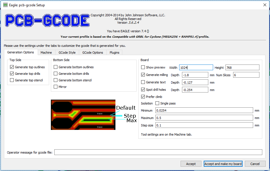
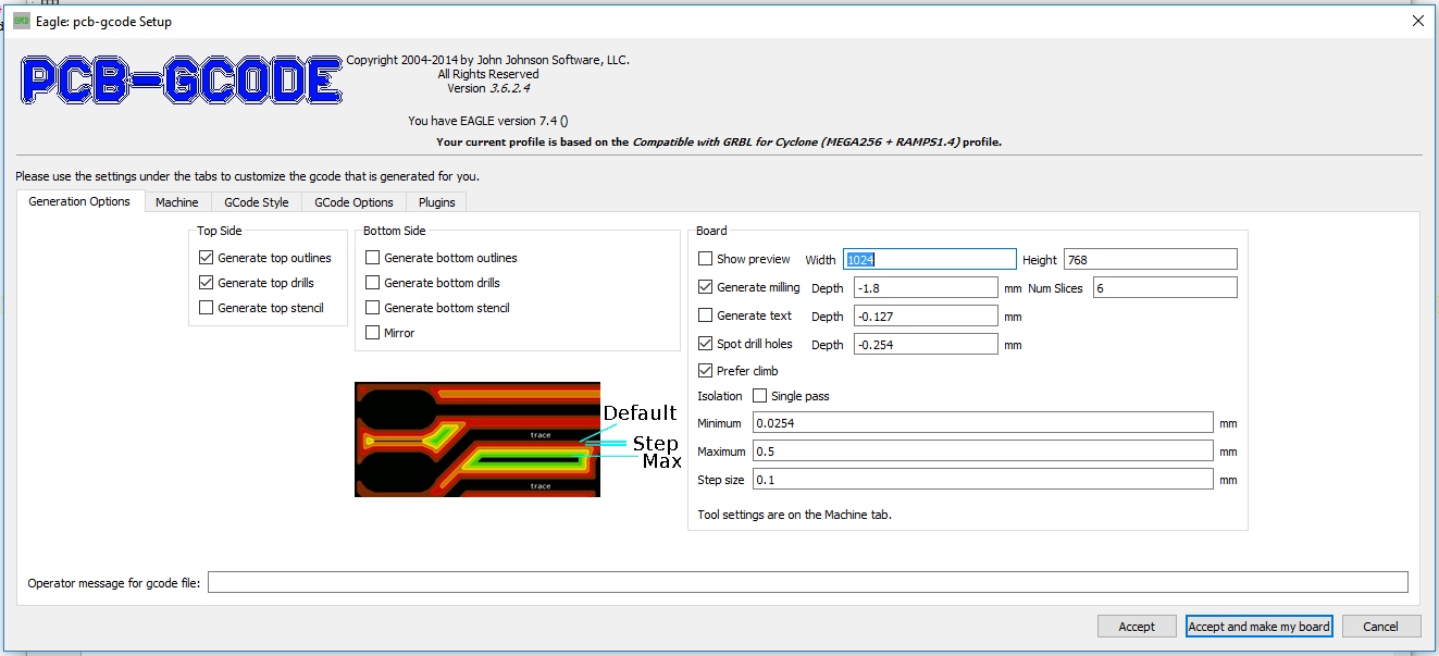
- Change all fields to the following settings if the settings I have provided in the pcb-gcode patch archive didn't do that for you already:
![]()
The new item that I added so that your outlines can be milled without destrying your endmill is on the right. Num Slices is the number of layers for cutting the outline. So at -1.8 mm cutting depth this results in {-0.3 mm, -0.6 mm, -0.9 mm, -1.2 mm, -1.5 mm, -1.8 mm} different cut depths.
Since the board in my example didn't need a bottom side, I deactivated the bottom layer features. However, I think the following should be selected for a dual layer board:
- Generate top outlines (there is a bug in this menu: If the top outlines are not selected, the top.etch file will not be generated. I might hunt that bug down later...). We will ignore the top.mill file!
- Generate top drills (we want to drill first)
- Generate bottom outlines (this is your mill file for cutting the outline of the board. We need to do that LAST!).
- The bottom.etch file will be generated automatically.
Please note: I have deactivated Show Preview because it annoyed me after a while. When you know what the result should be, you can deactivate it. It speeds up the process significantly - not that it's very slow in the first place...
![]()
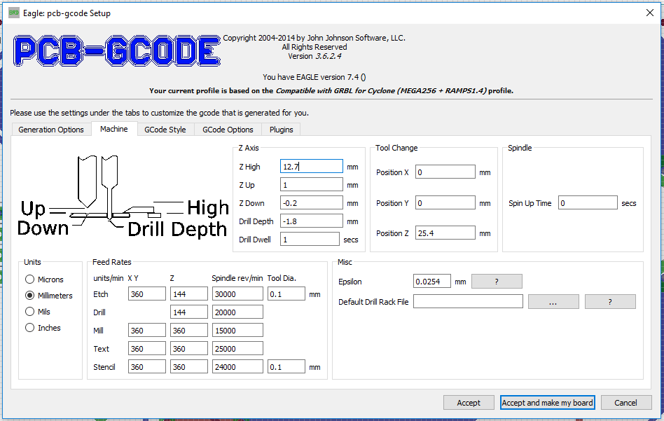
The machine uses the speeds that OtherMill suggests for milling FR1 copper clad board. That is by no means super fast but it looks impressive enough. My endmill holds up to that speed and I'm fairly confident that my 10 mill bits will last quite a long time for their huge $9 investment (for all ten).
![]()
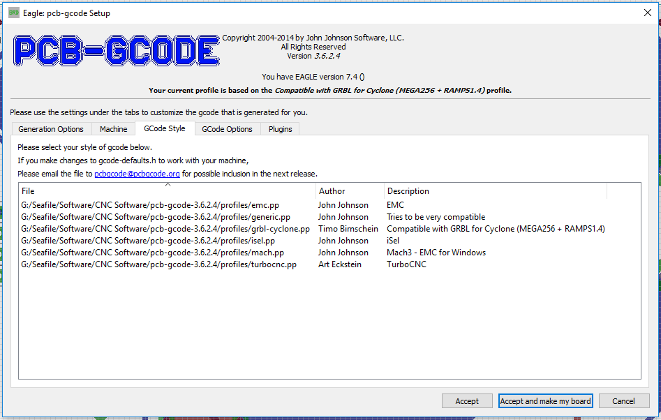
Select the grbl-cyclone.pp file and go to the next tab.
![]()
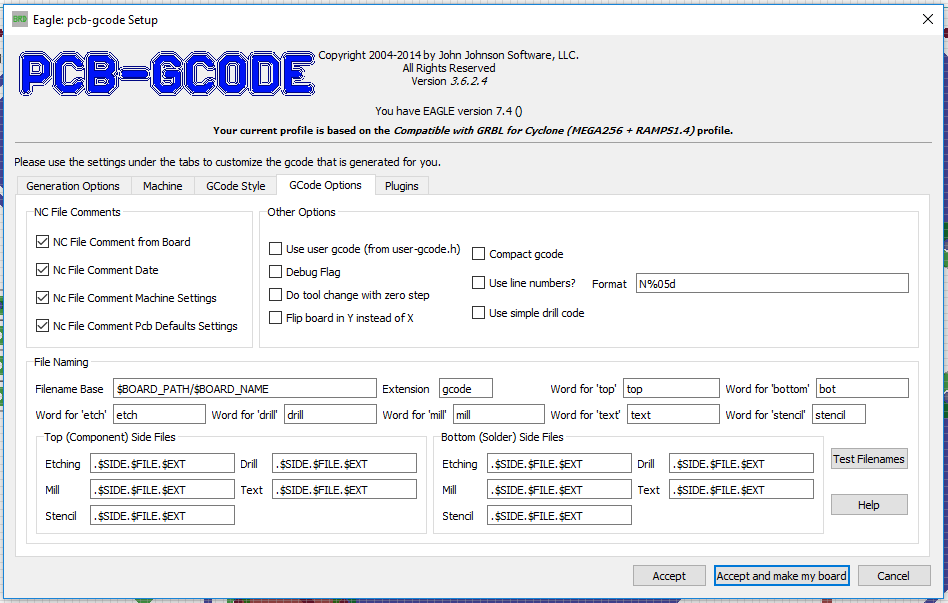
- That's it! Hit Accept and make my board.
Now, you should have a range of files in your project folder.
- filename.top.etch.gcode
- filename.top.drill.gcode
- filename.top.mill.gcode (ignore forever)
- filename.bot.etch.gcode
- filename.bot.drill.gcode (ignore forever)
- filename.bot.mill.gcode
We do not want to drill twice. If there is a tiny misalignment in your PCB machine, you will not drill into a hole but slightly off the center of that hole. It is very likely, that your drill bit will snap and we don't want that! Specifically, if it ends up in your eye!
Preparation of the PCB:
Make sure the PCB is flat. If not, use some gentle force to flatten it. When it is flat enough, use double sided tape and apply it with even distance throughout the area you expect the machine to mill. More doesn't hurt but it would be good to be able to remove the PCB from the mill bed after milling without destroying neither the PCB nor the bed.
Apply the PCB to the top left corner of the mill bed for the top side and make sure you have it aligned properly and totally parallel and flat to the top mill bed alignment fence. This step is important!
Fire up grblController with my modifications and connect to the mill. Go to the PCB Milling tab and home the machine. Otherwise it won't do anything but lock you out.
========================================================================
After homing, make a dry run in thin air without Z-probing and without any endmill attached. Make sure the system works properly before you even attempt to mill a board! Make sure your Proxxon actually spins up when milling should start.
========================================================================
Then, attach your V-shaped endmill and connect the probing wires to the PCB and the endmill. I press the one wire with a crocodile clamp onto the copper clad board and I attach the other wire with a crocodile clamp to the end mill. MAKE SURE YOU HAVE PROPER CONNECTIONS or you will break your endmill. I suggest testing it first by just touching your endmill with the second wire from the PCB to check if the machine stops instantly during the probing run. Check your wiring if it doesn't do that! Remember, the pin must be pulled to ground because it uses the internal pullup of the micro controller and it looks for a low signal on the I/O.
Confirm that the wires are connected using the check box and hit the Probe Z0 button. Z-axis moves, gently touches the surfaces and stops. Be prepared to emergency shutdown the mill during the first couple of Z-probes... It's probably a good idea to use even slower feedrates.
All done, let's get to business:
- Load up your top.etch.gcode file.
- Remove all your probing wires.
- Hit Start!
Milling begins now, the spindle turns on and you should see the system running through the PCB. Wait until done.
Move the spindle to safety and remove the v-shaped endmill and replace it with the drillbit of your choice!
Load top.drill.gcode and repeat the Z-Probing step. Be careful to actually have a proper connection. The drill bit will just break instantly of you don't.
It is wise to run the Home X and Y command first by pressing the button because you attached a new tool and it is likely that something moved in the process.
After successful Z-probing, hit Start again and wait until finish!
Move the spindle to safety and remove the drill bit and replace it with the v-shaped endmill!
Remove the PCB, clean the print bed and free it from any remaining double sided tape. Since it is wood in my case, I scrape it off instead of using chemicals. If the bed is not properly flat, you will run into problems with etching now. Apply the double sided tape on the TOP side of the board you just etched successfully and glue the board to the TOP RIGHT edge of the mill bed such that the old top left corner of the copper clad board is now in the top right alignment corner of the bed facing down.
========================================================================
At this point, I'm going to assume you have calibrated your X-Offset already!
If not, a drilled hole on the top side must line up perfectly with a drilled hole on the bottom side. In my case the offset was 160.3 mm in X and it should not be vastly different on your system. Maybe by 0.5mm but not more. That should give you at least an acceptable test PCB for starters. If you're planning on using DIP and though hole parts. Test it and calibrate it using one or two holes only! Drill a hole manually at X=60, Y=5 and then move to the bottom coordinate system and drill X=-60 Y=5 and it should line up perfectly!
========================================================================
- Load the bot.etch.gcode file from your PCB project directory.
- HOME THE MACHINE!
- Hit the Set Bottom Side Coordinate System After Fresh Homing button (WARNING: This will move the end mill to the new X0 position in the other corner. Make sure the path between X0 on the left and the new X0 on the right is free of obstacles or your endmill will break! I will add a checkbox for this later to make it safer and more idiot proof)
- Attach probe wires
- Probe for Z0
- Hit Start!
- Wait until finished.
Repeat with bot.mill.gcode but please attach you mill bit to the Proxxon spindle.
- Attach probe wires
- Probe for Z0
- Hit Start!
- Wait until finished.
Please keep in mind that the end mill will run exactly in the center of the mill line. There is no outer offset being calculated by pcb-gcode! You have to design that into your board layout yourself!
After all this you should have a board done. So much text! If you do it twice, you won't need any of this anymore because it's actually just pressing three buttons and changing some end mills and it's done. Takes no time to do but the learning curve is rather steep.
Congratulations! You have successfully milled your first double sided board with drilling holes and milling the outlines!
Thanks for reading all of this and I hope it helps you to get started!
-
Fixing an Eagle Plugin: pcb-gcode
06/19/2017 at 03:38 • 0 commentsFor a long time, people using Eagle for designing PCBs and pcb-gcode to generate mill files for RepRap based cnc machines complained a missing feature/bug in pcb-gcode:
All generated outline milling for the PCBs is cut in one go. As you can imagine, using a 1 mm endmill, even though carbide coated, doesn't like running through 1.8 mm fiber glass board in one go. People (including me) requested this feature for a while but it was no where to be seen.
One of the goals for this project is to have the simplest solution for everything possible. Very much like the OtherMill software, where everything just works straight out of the box as long as you follow the rules that are clearly laid out for you. Therefore, adding Z slices for the PCB outlines to the gcode by hand only to mill out the PCB was not an option anymore.
So, as if I didn't read enough foreign code this weekend, I dug into yet another code. Luckily, Eagle uses a scripting language for their ULP files that is very much like C, so adapting to that was easy and very straight forward.
I added a text field to the pcb-gcode-setup that allows to set the number of slices used to cut the outline of the PCB:
![]()
I also modified two more files to add the actual functionality. It turned out to be extremely easy since I essentially only added a text field and a for-loop where the commands are generated written to gcode file.
I'm very happy with the results. Just download pcb-gcode 3.6.2.4 and add my simple patch to it.
-
grblController Extention
06/19/2017 at 01:43 • 0 commentsToday, after installing the latest QT - which took forever! - I managed to get the grblController compiled on my system. It's actually very easy, just don't follow the build instructions. Installing the latest free QT is enough to build it, if you install the entire package including MinGW for your 5.9.x installation.
So after waiting for about 2h for the installation to finish I opened the project file and was presented with a nicely structured code in good old QT manner with signals and slots and the goodies I love about QT.
To my surprise it was easy to compile. There are two standard QT includes missing which I added into my fork of grblHoming (the actual name of grblController). After that was done, I started adding buttons and some text fields that I wanted as comfort functions for PCB milling.
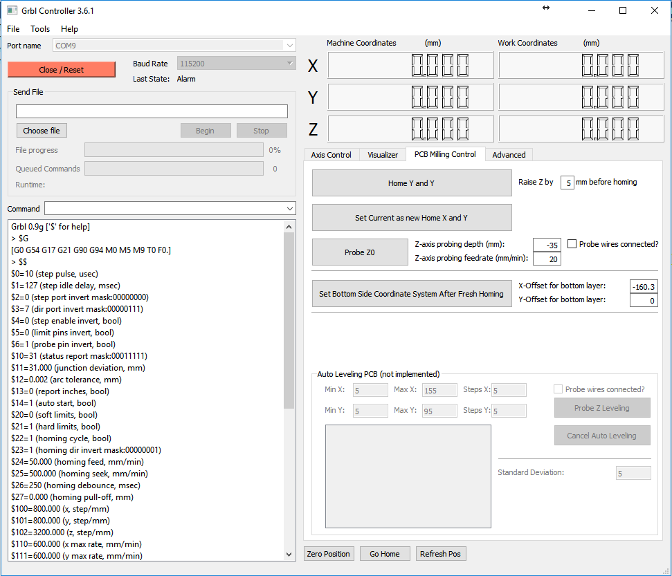
![]()
As you can see in the image above, I added a new tab specifically for PCB milling. It offers an actual homing command ("$H") for grbl, probing commands using some parameters for the probing as well as setting the machine offset after homing for milling the bottom side. All of this works really well now and I'm eager to start some actual projects with the mill.
At the bottom, I also started to add some stuff for autoleveling. I think this is a very useful function for PCB milling since the milling depth is in the -0.1 mm to -0.2 mm range and every little deviation from Z=0 will cause your track quality to suffer dramatically. So, if I run into problems, I might add this feature later. Right now, the mill bed is flat and I don't have an immediate need to implement this into grblController.
-
Now grbl controlled - by mistake...
06/18/2017 at 06:41 • 1 commentToday was an interesting day. I Almost completely wasted my Saturday by eliminating the stuttering that some people on the internet thought it was caused by Marlin when running over very small line segments. The internet claimed, Marlin has issues with those super small line segments and can't keep up. But the developer said it was fixed.
Apparently, it was.
I invested the first three hours of today getting grbl for the Cyclone mill to work on my mill. It should have been straight forward if Cyclone would use standard pinouts. But grbl runs to MAX endstops by default, so I wired up my endstops to MAX on the RAMS1.4 board. However, the Cyclone port only uses MIN endstop pins. As soon as I figured that out the machine was ready to be tested.
The grbl for Cyclone seems to be using a different homing pattern in general. Even when the offset from home is set to 0, grbl moves the tool head away from the endstop so that the mechanical endstop turns OFF again. Since these mechanical endstops have a hysteresis, my previous X0, Y0 is now slightly offset. That means I have to recalibrate my bottom layer milling offset again as well. It won't just be Y-162 anymore. But we will see.
And then the actual issue of the day: It wasn't Marlin. It's the gCode sender - AGAIN!
I experienced this issue before when I tried to use my K40 laser cutter for image engraving with a new laser power value every 0.1 mm. I had to write my own gCode sender in order to make that kind of data rate happen. And now, I tried to use CNC-gCode-Controller again, with all its comfort functions, and I see.... it still stutters exactly like Marlin! We're 4.5h in at this point.
So I tried my own gCode sender and voila - it runs buttery smooth. But my version is console based and doesn't offer any other features than sending gCode as fast as possible to grbl.
So I tried to dig into the horrible Java code of CNC-gCode-Controller and tried desperately to identify where the gcode is actually sent to grbl and how it was organized. A hopeless endeavor since there is practically no documentation and (in a classic Java manner) so many classes and helpers and whatever Java construct you can think of that I as C++ developer had to give up. I don't like Java. I only use it when I absolutely have to.
We're 9h in now.
The remaining 3.5h of the day, I restarted my search for some GUI based system that might be fast enough (I'm not laser engraving here) to send a PCB to grbl, so I found grblController again! And best of it is, IT WORKS!
Unfortunately, I still miss a bunch of comfort functions! Here is an example:
To mill the top side of the PCB I have to manually send
- $H - for homing the machine and have it execute the first init line I gave it which is
- G92 X0 Y107 - this sets the coordinate system at home X0, Y0, Z0 to X0 Y107 (done automatically by grbl now using $N0=G92X0Y107)
- G0 X0 Y0 - to run the machine to actual PCB home for top side to be able to install a copper clad board (done automatically by grbl using $N1=G0X0Y0)
- G38.2 Z-10 F20 - to probe for endmill - PCB contact with attached probe wires
- G92 Z0 - to reset the coordinate system for Z to 0
Now I can hit start! I would love a button for the first step and another button for the Z probing.
To mill the bottom PCB I have to do even more:
- $H - for homing the machine and have it execute the first init line I gave it which is
- G92 X0 Y107 - this sets the coordinate system at home X0,Y0 to X0 Y107 (done automatically by grbl now using $N0=G92X0Y107)
- G0 X0 Y0 - to run the machine to actual PCB home for top side (done automatically by grbl using $N1=G0X0Y0)
- G92 X-160.3 - to let the machine know it is now in negative space with working coordinate at X=-160.3 mm
- G0 X0 - to run the machine to actual PCB home for BOTTOM side
- G38.2 Z-10 F20 - to probe for endmill - PCB contact using my probe
- G92 Z0 - to reset the coordinate system for Z to 0 and leave X and Y where at is
Again, buttons and confirmation would be cool to have to be less prone to user errors.
Right now, I'm trying to install QT the free edition to try and compile grblController from sources. But since the online installer can't finish downloading all the packages I have very low confidence that will be able to compile it and add my buttons to it - or even that nice auto leveling feature from PCB-gCode-Controller... sigh...
EDIT: The offline installer version of QT 5.9.0 for Windows seems to be available as well. We'll see what tomorrow brings.
EDIT 2: I just swapped X and Y axis and updated the gCodes above accordingly.
-
More Calibration Work
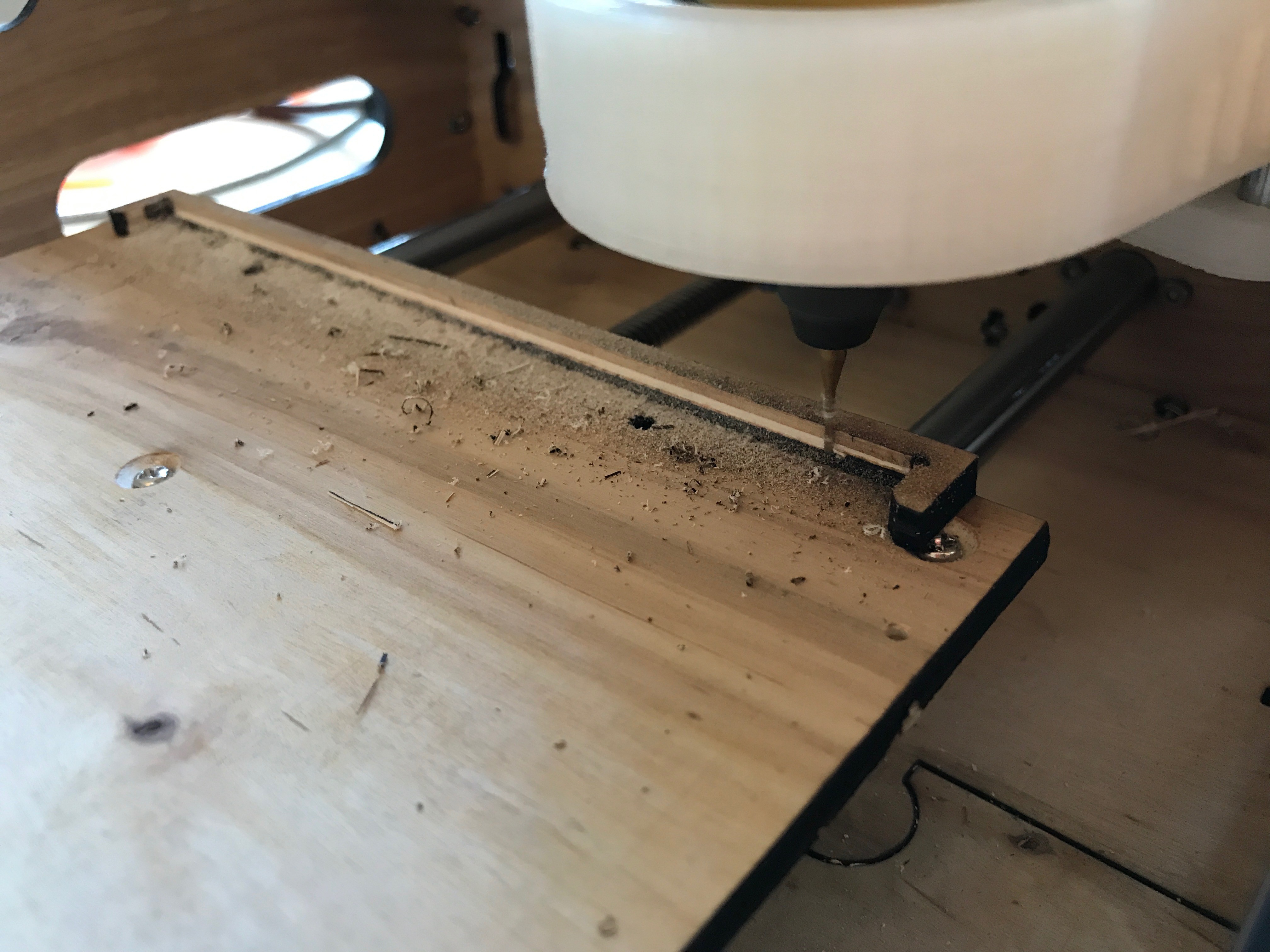
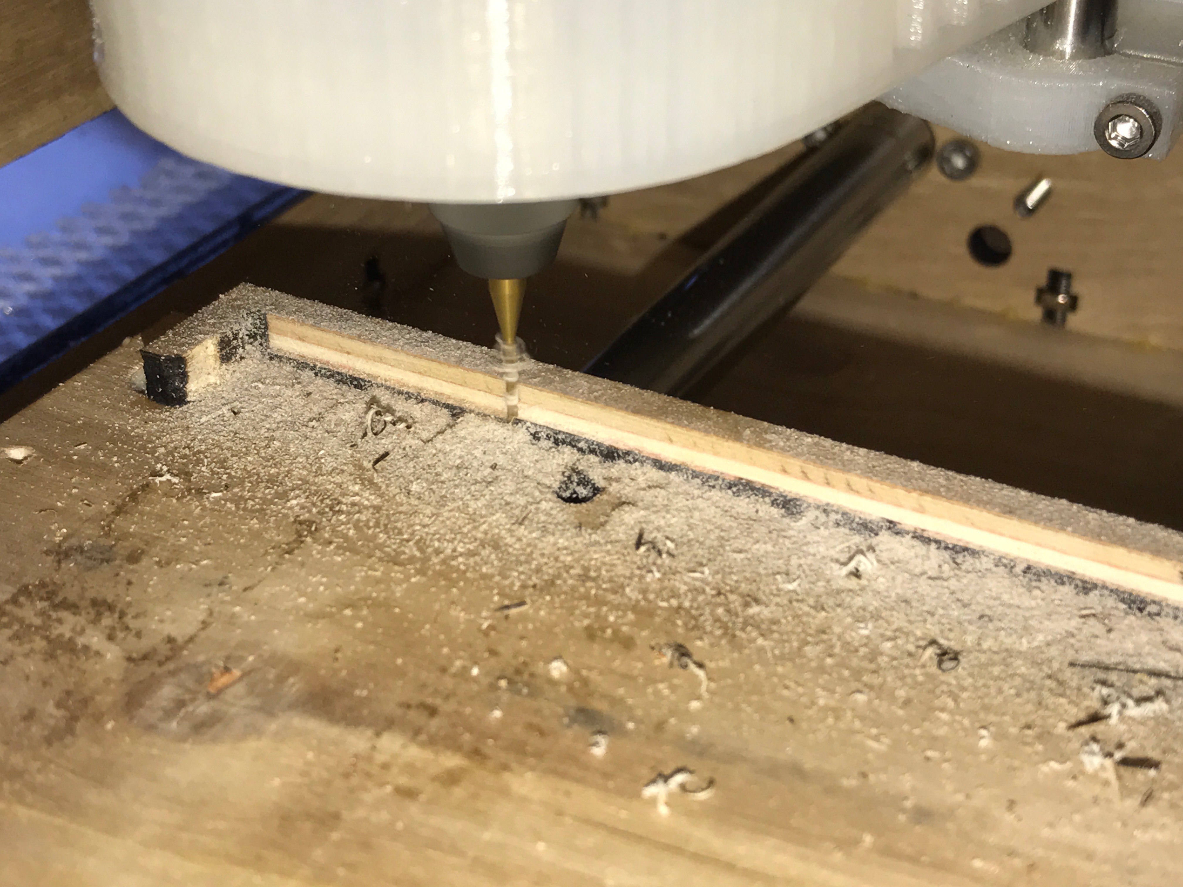
06/15/2017 at 21:34 • 0 commentsA couple of days ago, I managed to install the wooden mill bed. I made it from the most flat sheet of plywood I could find so that I don't really have to deal with any Z-height calibration on the copper board itself. Just put it in there and start milling. I also glued the X-Limit Fence (?) in place and milled it down to be absolutely parallel to the Y-Axis. To do that I created a super simple gCode file by hand and let it run. It turned out really well and I'm now ready to do the Y-axis offset calibration to mill the bottom side of PCBs.
![]()
![]()
Milling top side of PCB
- Home X,Y
- Glue Copper Clad Board to upper left corner of table using double sided tape
- Move to 0,0,5
- Attach Z-Probe to mill bit and PCB
- Home Z
- Load file into PCB-Gcode-Controller
- Optimize file
- Mill top side in positive space
Milling top side of PCB
- Home X,Y
- Glue Copper Clad Board to upper right corner of table using double tape
- Move to offset
- Use G92 Command to set new machine location (like G92 Y-162) [requires one time calibration of Y-Offset to be able to mill properly in negative space]
- Attach Z-probe to mill bit and PCB
- Home Z
- Load file into PCB-Gcode-Controller
- Optimize file
- Mill bottom side in negative space
That's literally all that's required for etching. The same is true for drilling and outline milling.
Steps to etch double sided PCBs:
- Mill top side
- Mill bottom side
- Drill bottom holes
- Mill outline
One remark: I haven't found the settings for Z-depth per run in the PCB-Gcode UPL script for Eagle. That means it tries to mill the outlines of the board in one go! This will likely break your mill bit because it imposes very high stress on it! I currently modify the gcode by hand by copying and pasting the milling multiple times while adjusting the Z-height every full run around the outline of the pcb. Not ideal, but if you want full automation, I suggest using a different software or modify the ULP script.
-
The Moment you realize...
06/11/2017 at 06:51 • 0 comments... you should have measured all components before cutting the enclosure.
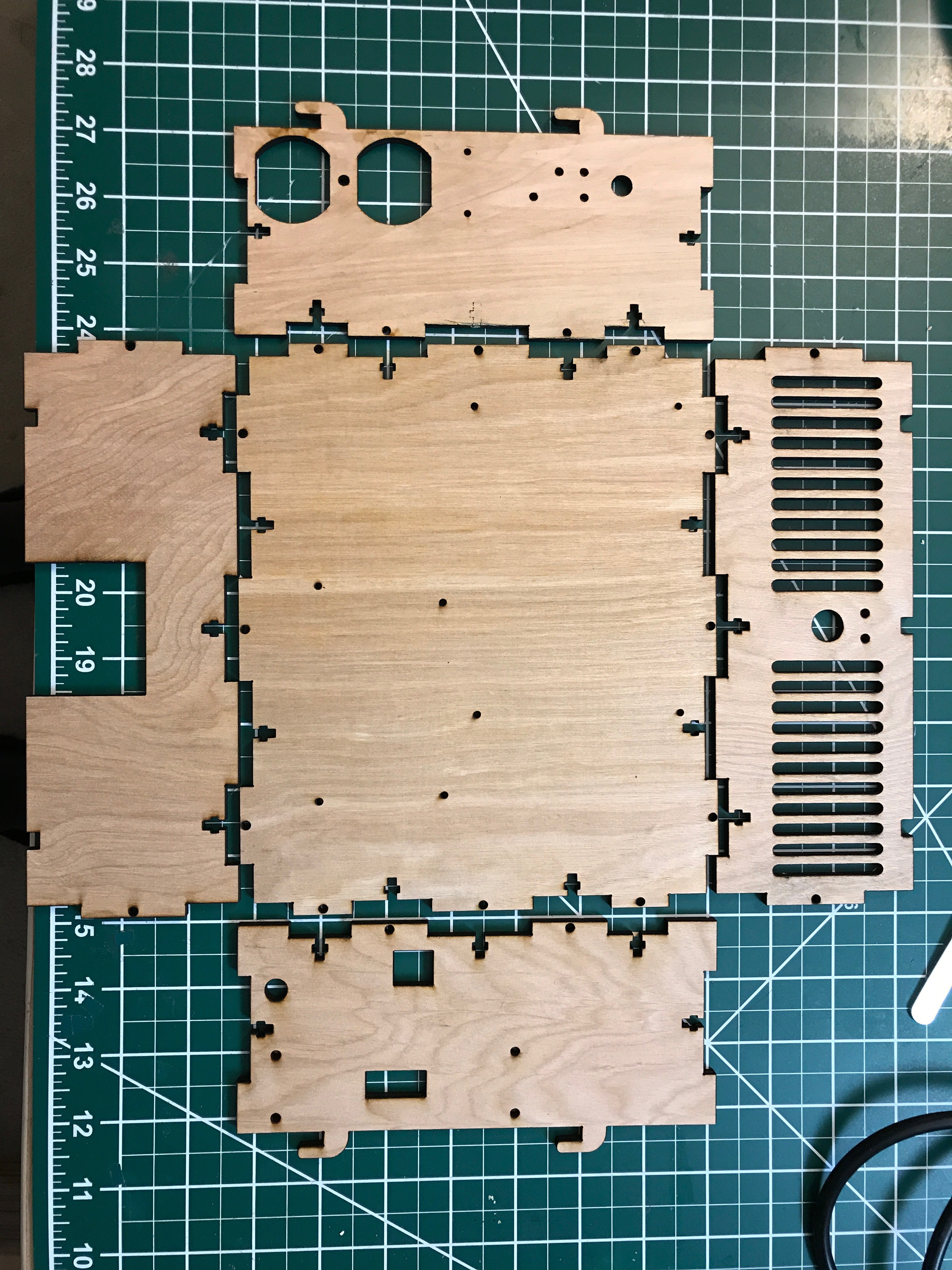
I started by laser cutting the enclosure parts which required me to recalibrate my laser Z-table because the cuts became increasingly unreliable. In the end, they turned out extremely well:
![]()
![]()
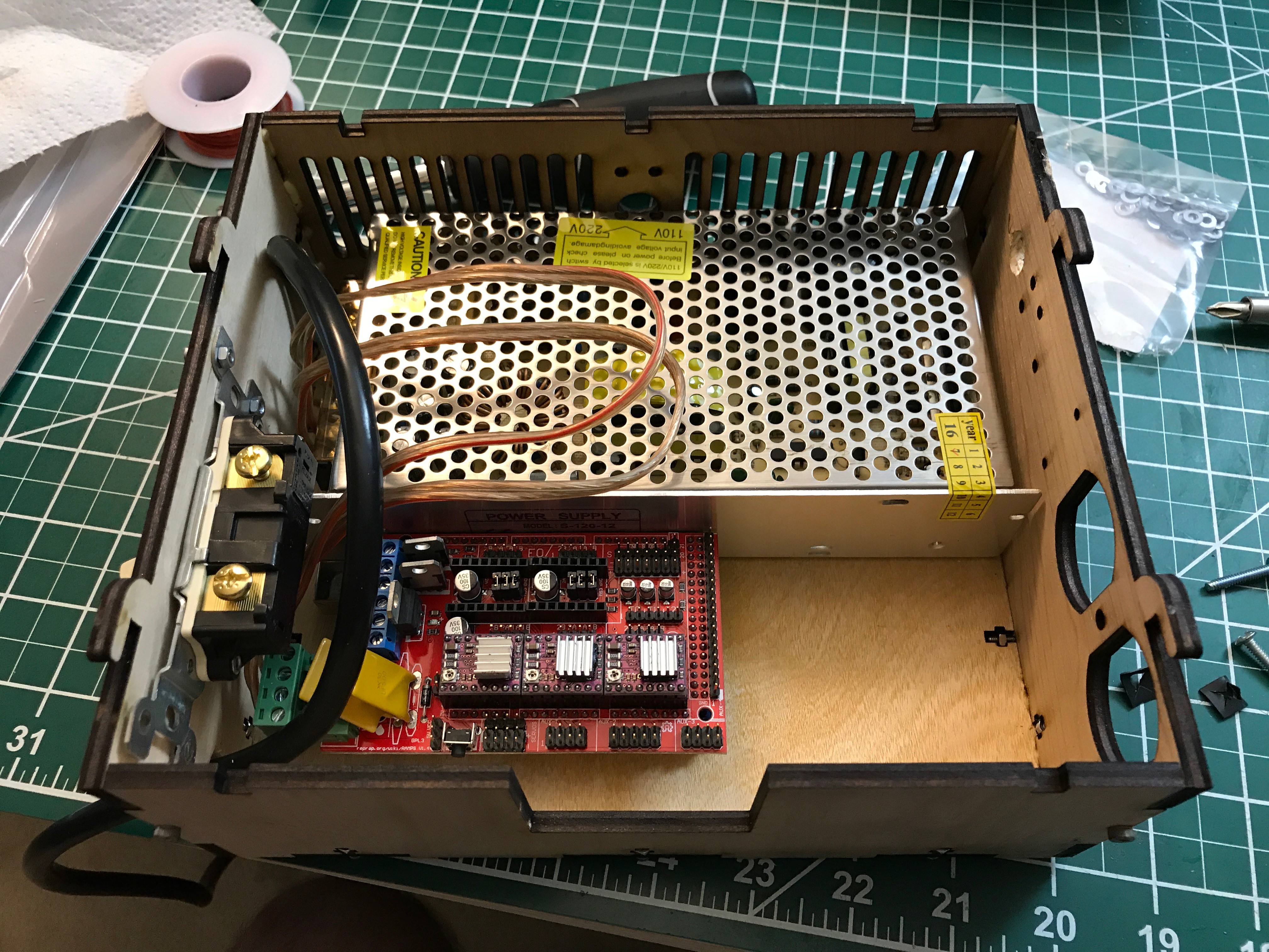
Tonight, I put together the backpack of the mill. It had some minor issues here and there, mostly hole sizes or missing holes. Nothing too serious.
![]()
![]()
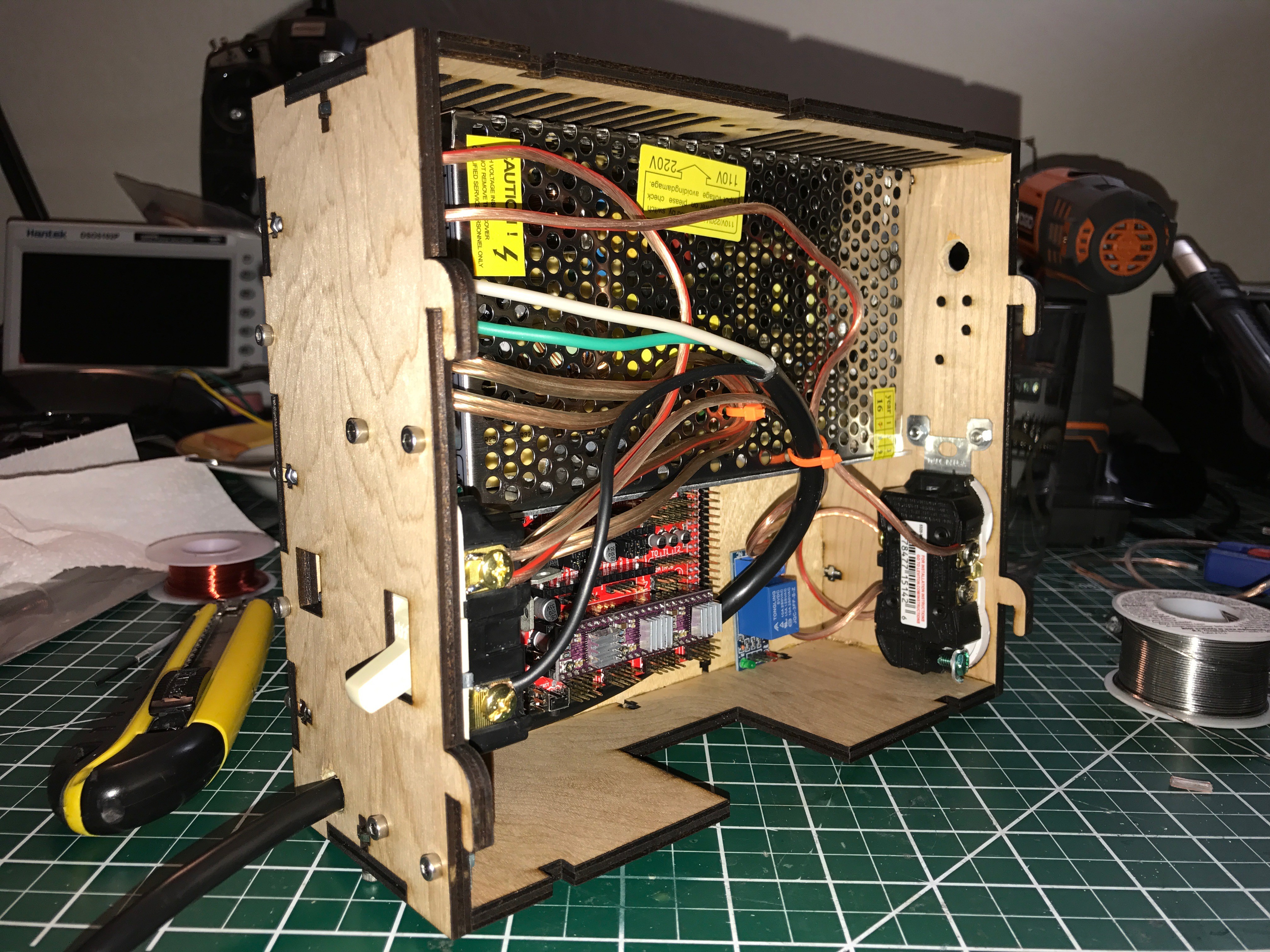
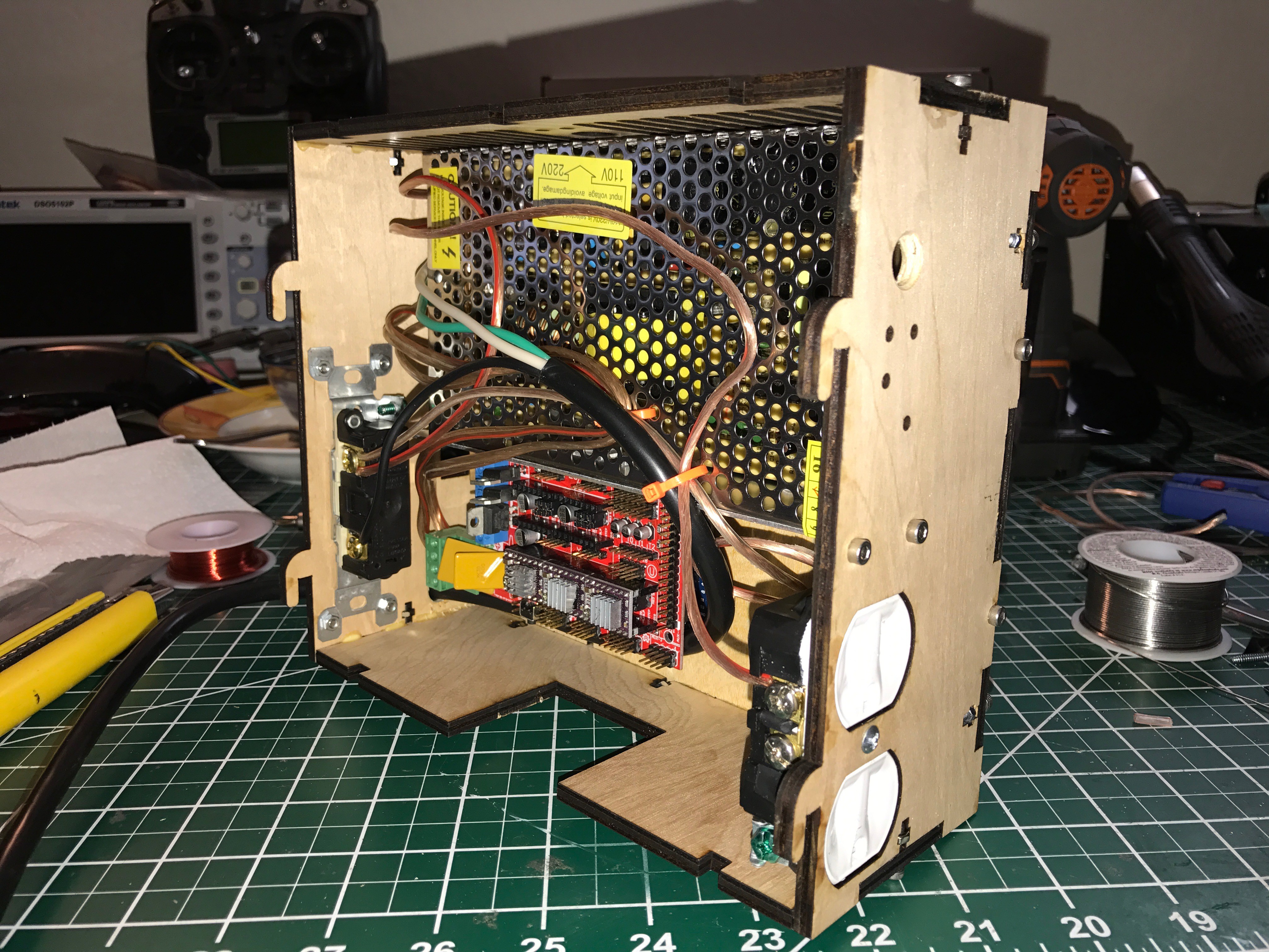
However, after everything was finished I wanted to slide the backpack into the mill and realized that the X-Axis stepper motor collides with the heat sinks on top of the stepper motors drivers.
![]()
![]()
That was quite a bit annoying!
I wanted to have a very neat little mill that I could practically take everywhere and that just works out of the box. Now I can choose between
- a gap between the back of the mill and the backpack or
- an additional box with a string if wires sticking out.
I think I chose the first option since it is the more reliable, less moved option that should protect the wiring harness more.
I will update the enclosure so that anyone interested will be able to build a mill without those issues.
So far, I'm very happy with what I could accomplish this weekend. The mill runs great, there are a bunch of open points on the list but this is certainly an excellent start for the new PCB mill for under $200.
-
Success on first try!
06/10/2017 at 22:08 • 0 commentsI can report success! To my big surprise, this works! And it works really well!
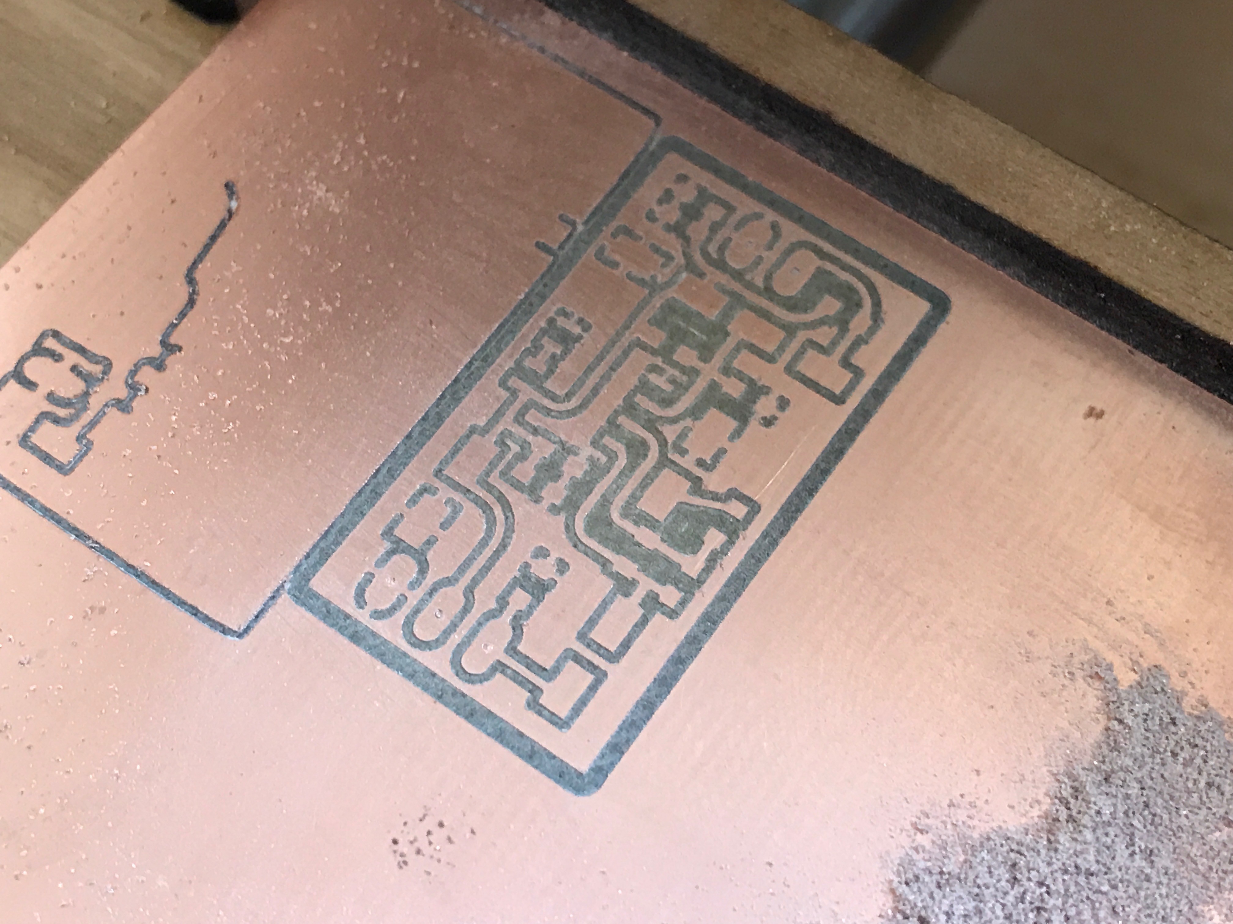
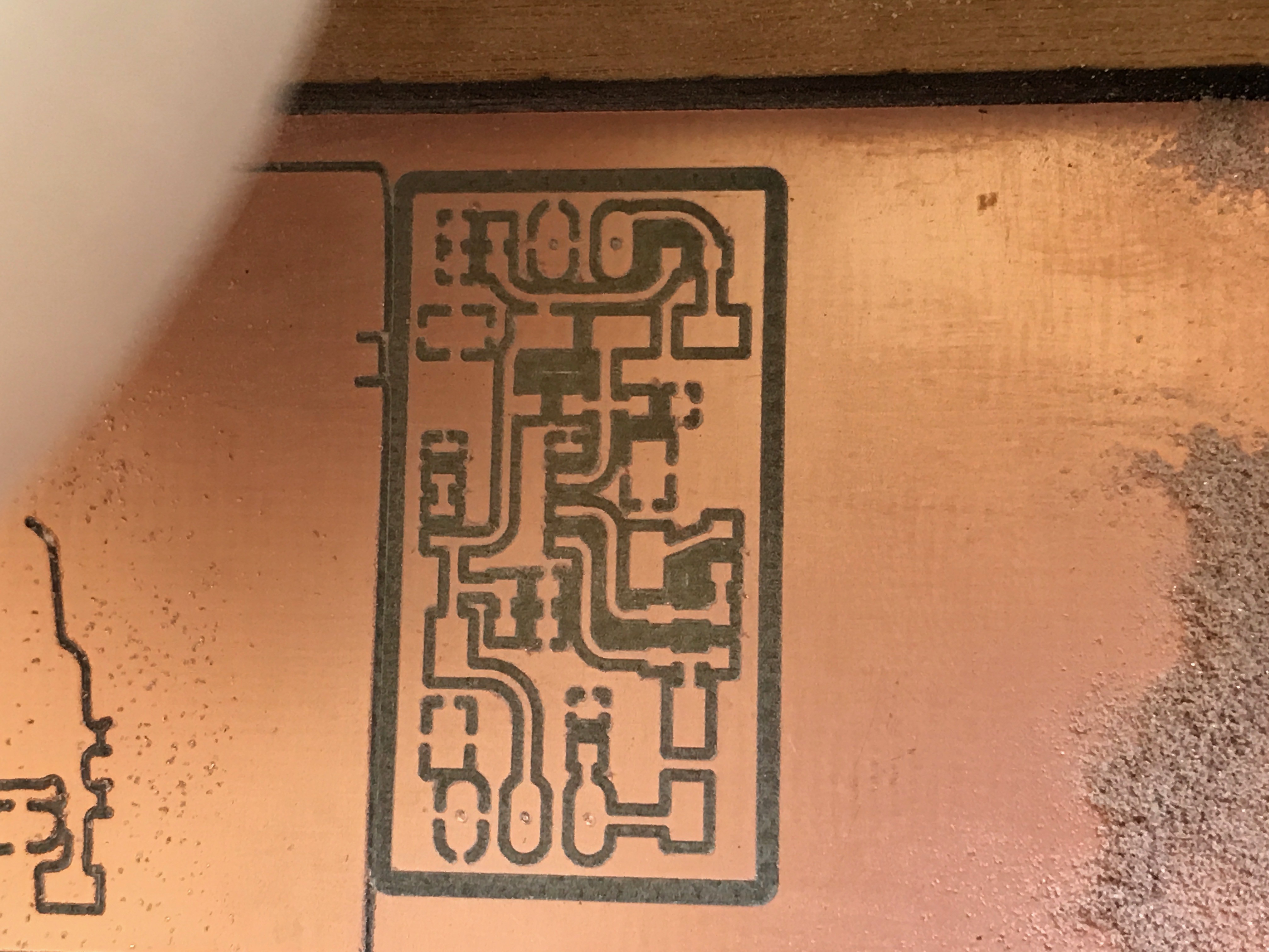
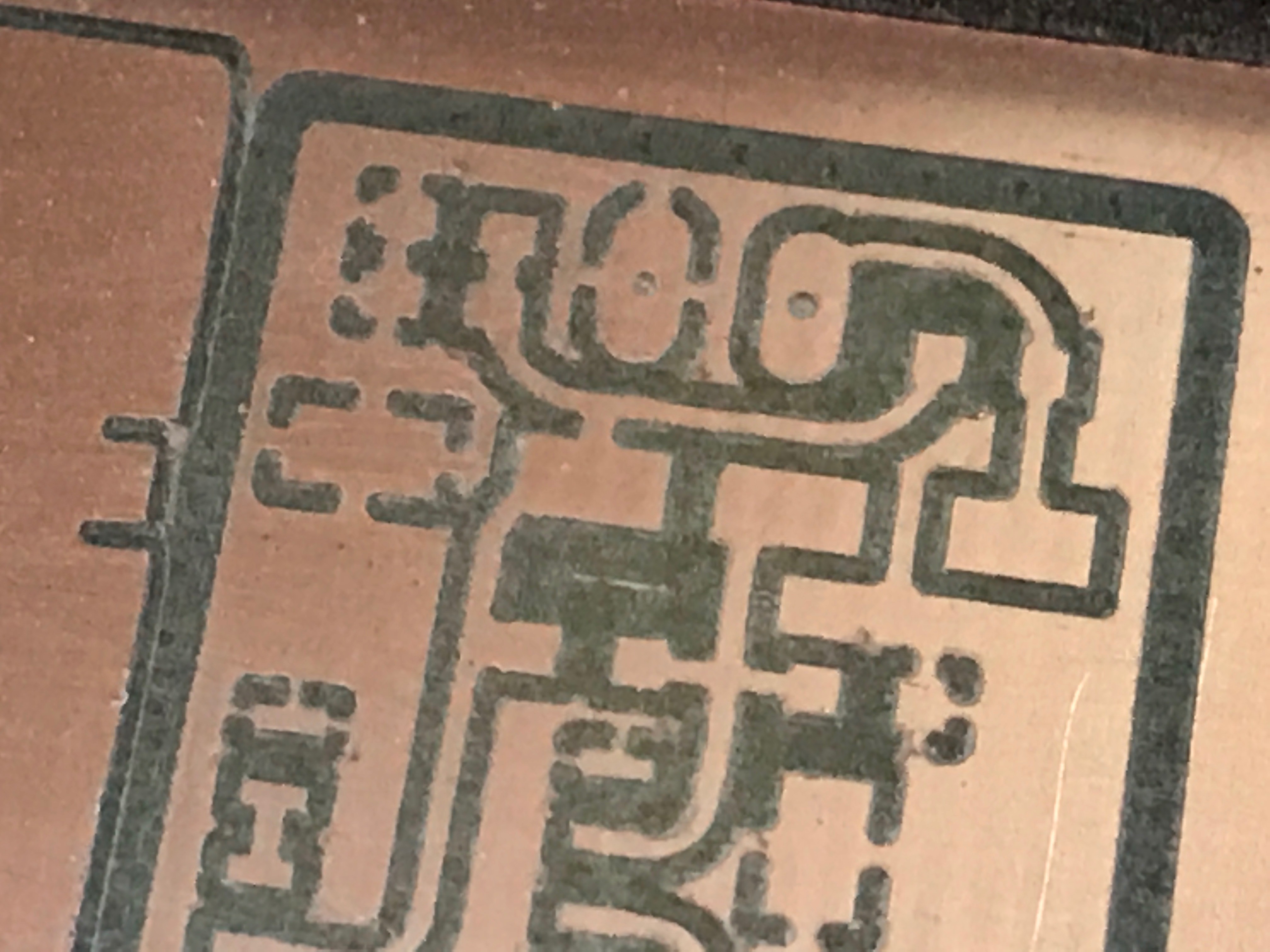
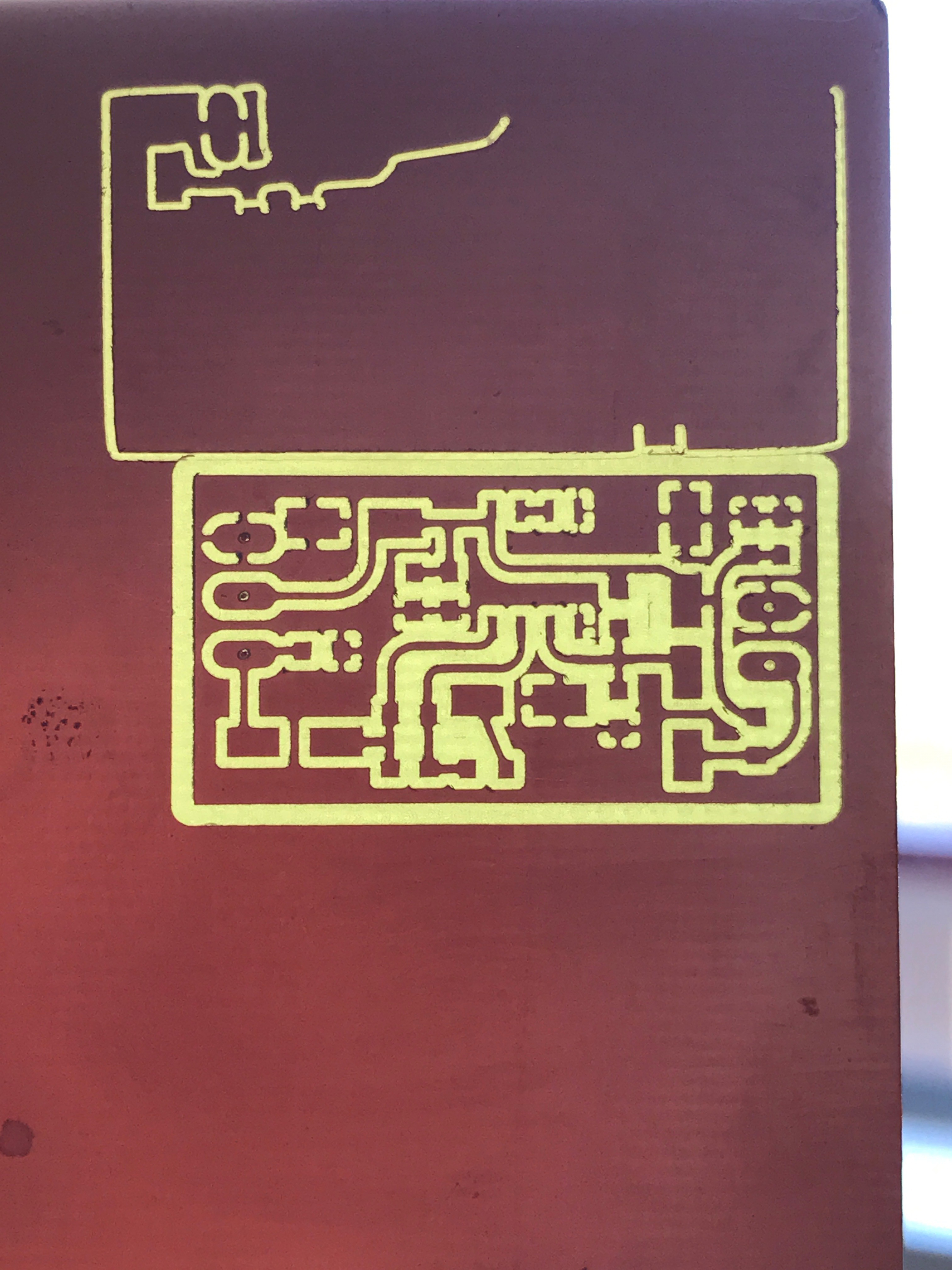
I ran one of my past projects on the mill just a moment ago. It is a microphone pre-amplifier that I used for my YouTube channel.
I can now autolevel the Z-height by using the actual mill bit and a crocodile clamp as a probe. That works really well. I will also try and use the CNC-gCode-Controller bed leveling function to probe the entire PCB to adjust automatically for unevenness of my board and mill bed.
![]()
![]()
![]()
![]()
For $200 this is a really good result. Much better than the results on my 3D printer and quite a bit better than on version 1 of this mill. I'm actually very surprised how well the cheap plywood works for this. The only downside is the noise the machine makes during milling. But that is something I can't really change except I build a large box with lots of sound dampening around it. But maybe that's even an option as long as I don't disturb my neighbors.
This board needs some minor cleanup using 400 sandpaper and then it's good to be soldered.
Next steps:
- Find a solution for noise reduction, specifically to the table it's standing on
- Make a new Z-Probe board with mounting holes
- Mount the Z-Probe board in a good location
- Laser cut the power backpack
- Integrate power backpack
- Identify a reliable configuration for drilling all holes with different bit sizes
- Identify a reliable configuration for milling the outlines of any board
- Identify a reliable configuration for milling double sided boards
-
Pololu Stepper Motor Driver Issues
06/09/2017 at 04:50 • 0 commentsIt seems, upon further inspection, the kit that I bought off of ebay containing
- 3 stepper motors
- a mega256 arduino clone
- a ramps 1.4 clone
- 3 end stops
- a NTC for a printer bed
- 5 DRV8825 stepper motor drivers
is not actually set up to run off of 12V or the ramps board is so clone/fake that the wiring on the board is wrong and the system is not driven correctly.
When I run the stepper motors at very low speeds the steppers seem to miss steps. This blog analyzed the problem and found a rather interesting solution to the issue that the driver does not seem capable of driving low voltage motors at high voltage and low current. It seems to miss microsteps and it seems the results are pretty bad. I have a similar problem running at such low speeds even though it will no influence me as much. I also tested the good old A4988 driver in my board and to my big surprise it produced a very similar missed microsteps pattern even though the same driver works perfectly fine in my laser cutter on my own control board at random speeds.
I have yet to identify the actual problem because it seems unlikely that Pololu would release a driver chip that is essentially unusable at low speeds.
Does anyone have any ideas and solutions regarding this problem?
-
Bringing a new PCB Mill to Life
06/09/2017 at 02:01 • 0 commentsFor a very long time there was only one option for PCBs manufactured at home: Use your already existing photo developer studio and a well calibrated acid bath. Later simpler methods of getting the positive onto the copper clad board came up like toner transfer using irons or modified paper laminators or even modified laser printers to print the positive resist directly onto the board.
However, some years ago, after having done most of the above, I thought it was time for a change. PCB mills were in the range of $15,000+ and could be regarded as unobtainable for the private person. In 2012, some people started modifying their Reprap 3D printers and attached Multitools and commercial companies like OtherMill developed a closed source platform for $4,500. A very much overpriced system that was able to produce incredible results with excellent software - as long as you're a MAC user. But seriously. Mac and $4,500 was a no go for me so I started my own development based on open source tools like Marlin, some plugins for Eagle Layout Tool and CNCGcodeController.
The first iteration of this PCB Mill had a thick Aluminium enclosure, was very heavy for its size and used 3D printed standard CNC builder components that I designed to be able to quickly iterate CNC machine designs.
![]()
However, this approach was insanely complicated and led to a long and complicated assembly and used way too many screws. I also sold it when I moved to the US.
![]()
![]()
![]()
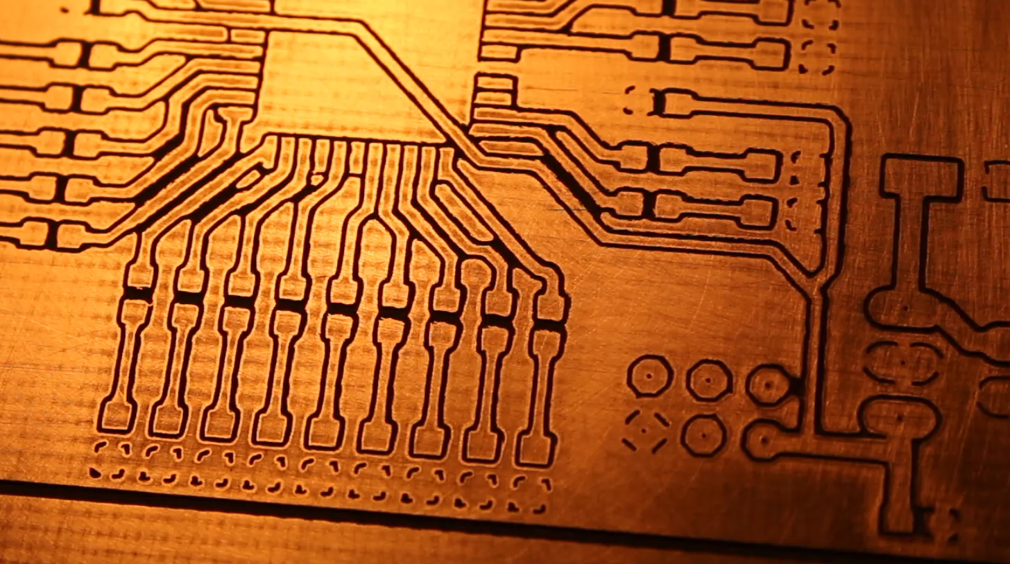
(Please note in the above image that it was possible to route a signal wire UNDER the 0603 resistor on the right. This is a FT232RL board that I made with it the first generation. The board on the right was not cleaned up using sand paper, yet)
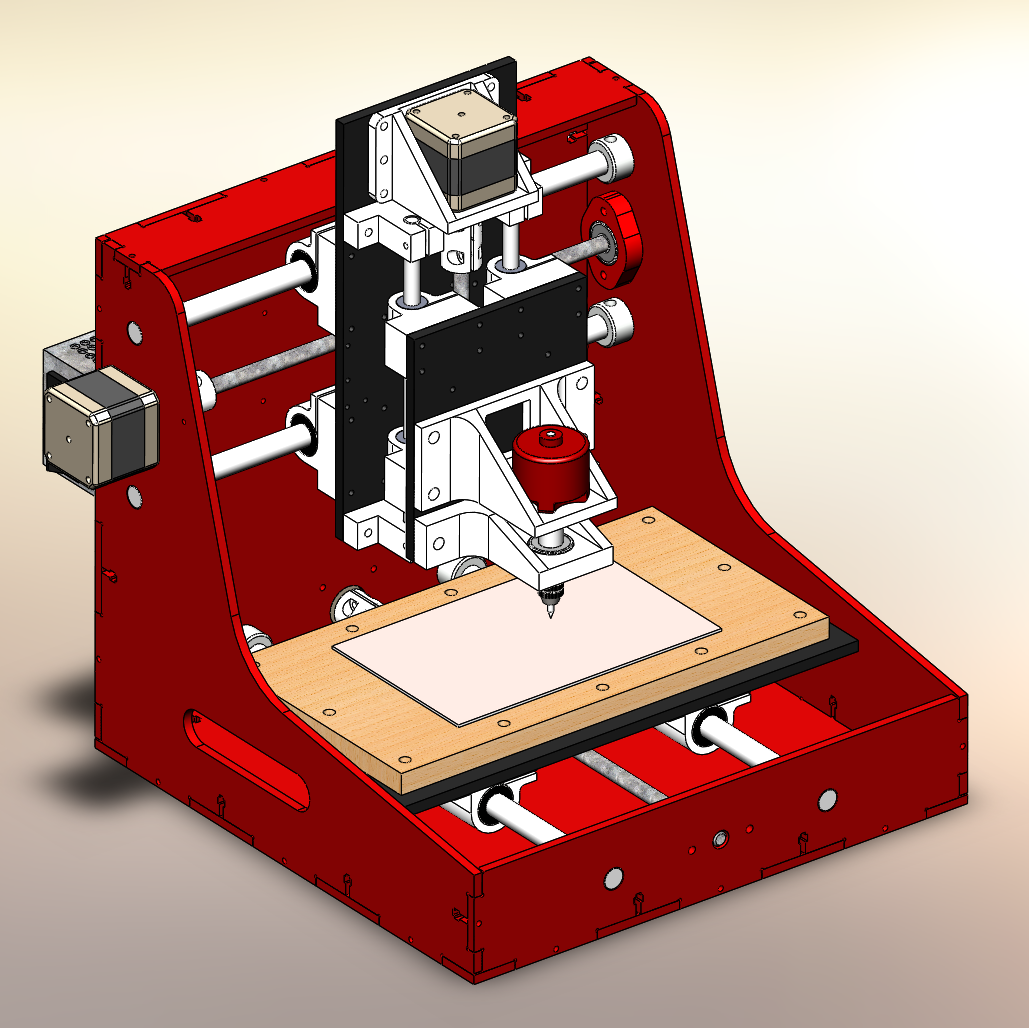
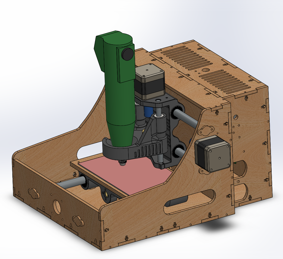
A couple of weeks back I started thinking about a new, much simpler design that would allow me to use only three 3D printed parts instead of 21. I also wanted to integrate more features into the design like mounting points for mechanical end stop switches, proper spindle drives and a standard Multitool.
![]()
In my case my beloved Proxxon FBS 115/E. The most precise Multitool I know of - compared to the terrible Dremels with their ridiculously unprecise collets.
Current State:
- Axis move
- End Stops work
- No noticeable play so far
- Plywood construction is a bit soft but we will see if this affects the milling of PCBs
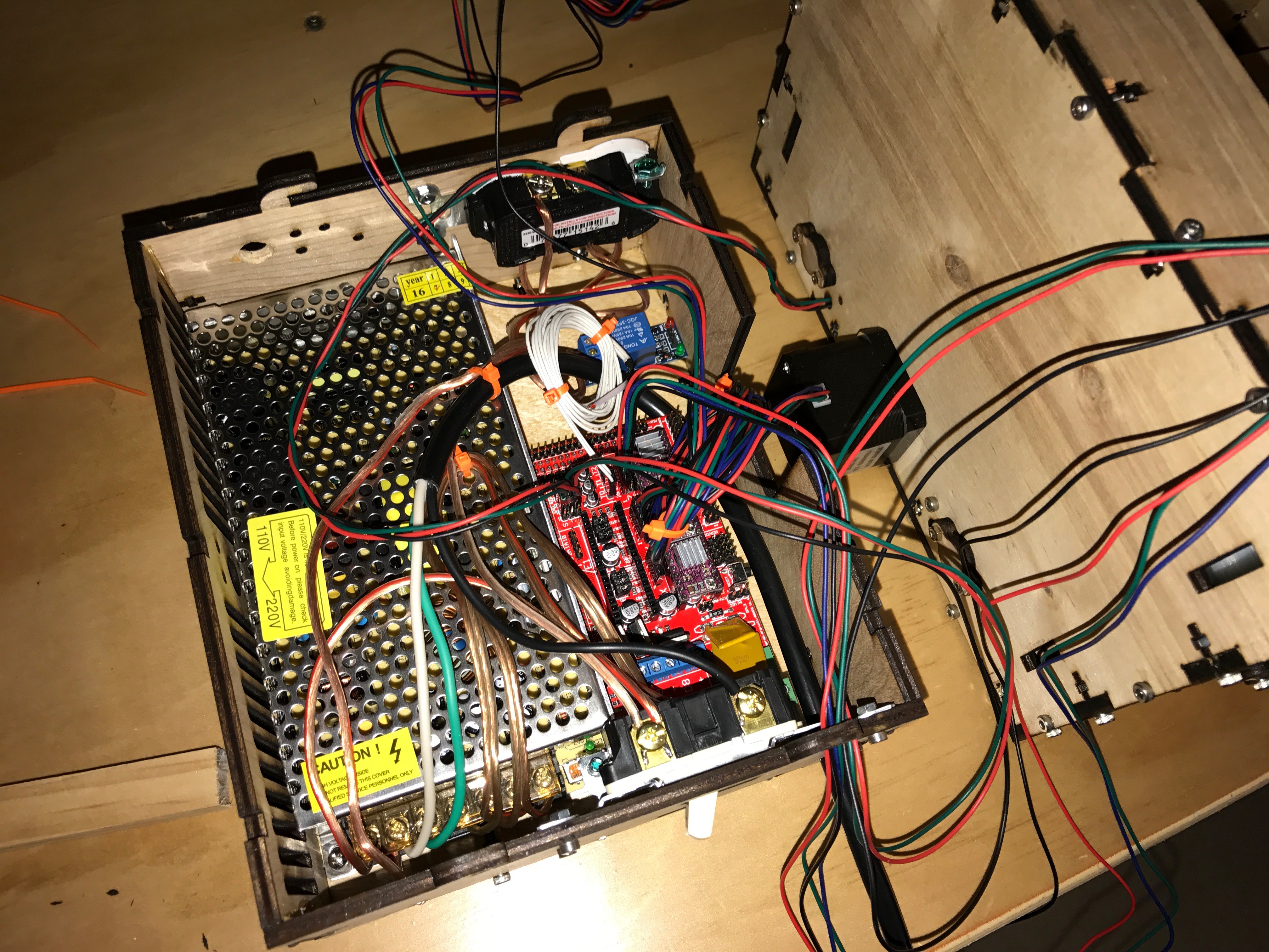
- Power backpack not yet finished, therefore wild wiring for testing and calibration
- Mill table still missing - including a fixture to mill double sided PCBs precisely
- Milling and drilling test
Sub $200 PCB Mill that doesn't suck!
A PCB mill inspired by open source CNC 3D printers with a custom design to fit standard size copper clad boards (6" x 4" / 160mm x 100mm)