Project goal: create an easy method to build the actuator with multiple strands of wire.
A similar project was undertaken at McGill 20 years ago http://www.cim.mcgill.ca/~grant/sma.html.
A shape memory alloy actuator that can move useful loads over decent distances.
Already have an account? Log in.
To make the experience fit your profile, pick a username and tell us what interests you.
Project goal: create an easy method to build the actuator with multiple strands of wire.
A similar project was undertaken at McGill 20 years ago http://www.cim.mcgill.ca/~grant/sma.html.
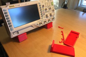
The first mould(right) didn't turn out great. There was an air bubble that got trapped and some silicone flowed under the pulley. I could have cleaned this up but the imperfections of the printed/lathed were really obvious in the mould.
I printed out a second pulley and used the Dremel as a lathe rather than the drill press, which made for a much cleaner part. The void in the middle is the pulley, and the second try is on the left. The second mould is really good, time to cast the first pulley!
Tonight I started getting the pulley mould ready. PLA is a low temp plastic, and the heat of the SMA wire damages them quickly. Also, my printer doesn't have the ability to accurately print parts that small.
I printed out a pulley, jammed it on a nail, and put it in my drill press in to make a quick and dirty lathe.
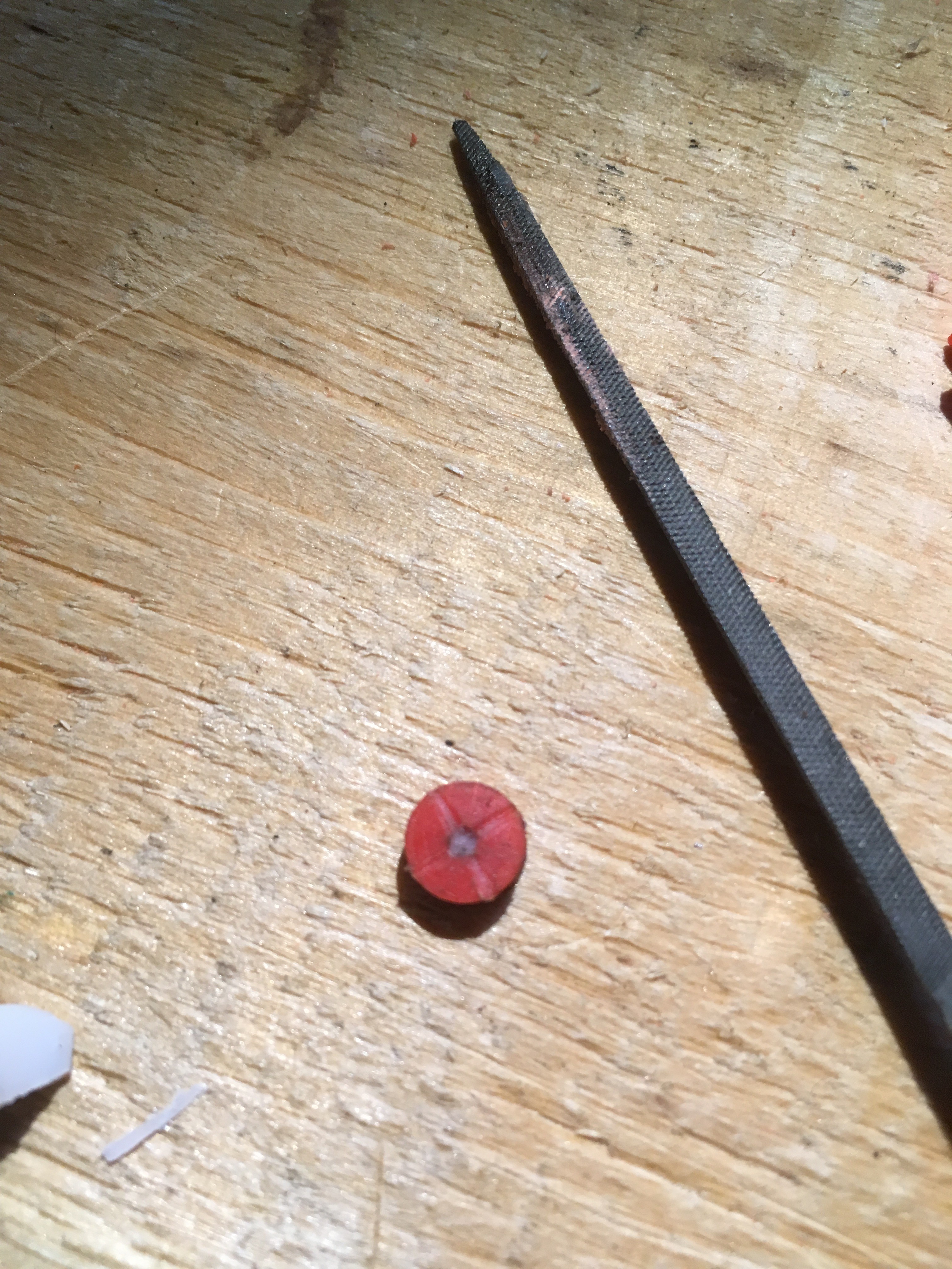
I used some files to grind the pulley to a more circular shape. The result wasn't perfect, but good enough for now.
The next step was filing a target for drilling the cast part and filling the shaft hole with a bit of wax. From my experience holes that small can't be moulded.
Next I printed out a cup for the mould, placed some nuts in case I want to do a 2 part mould in the future, and I'm waiting for my mixing cups to print.

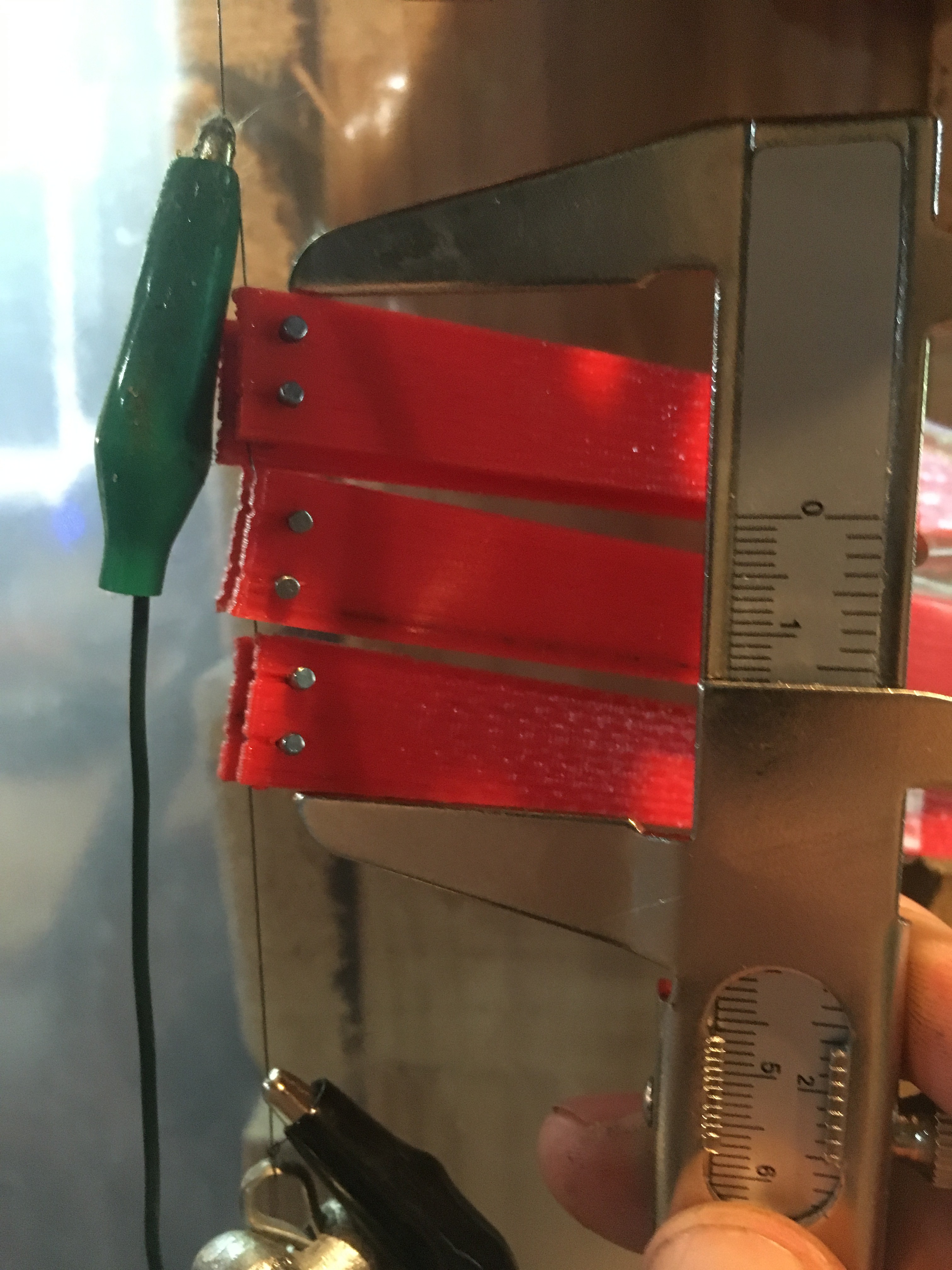
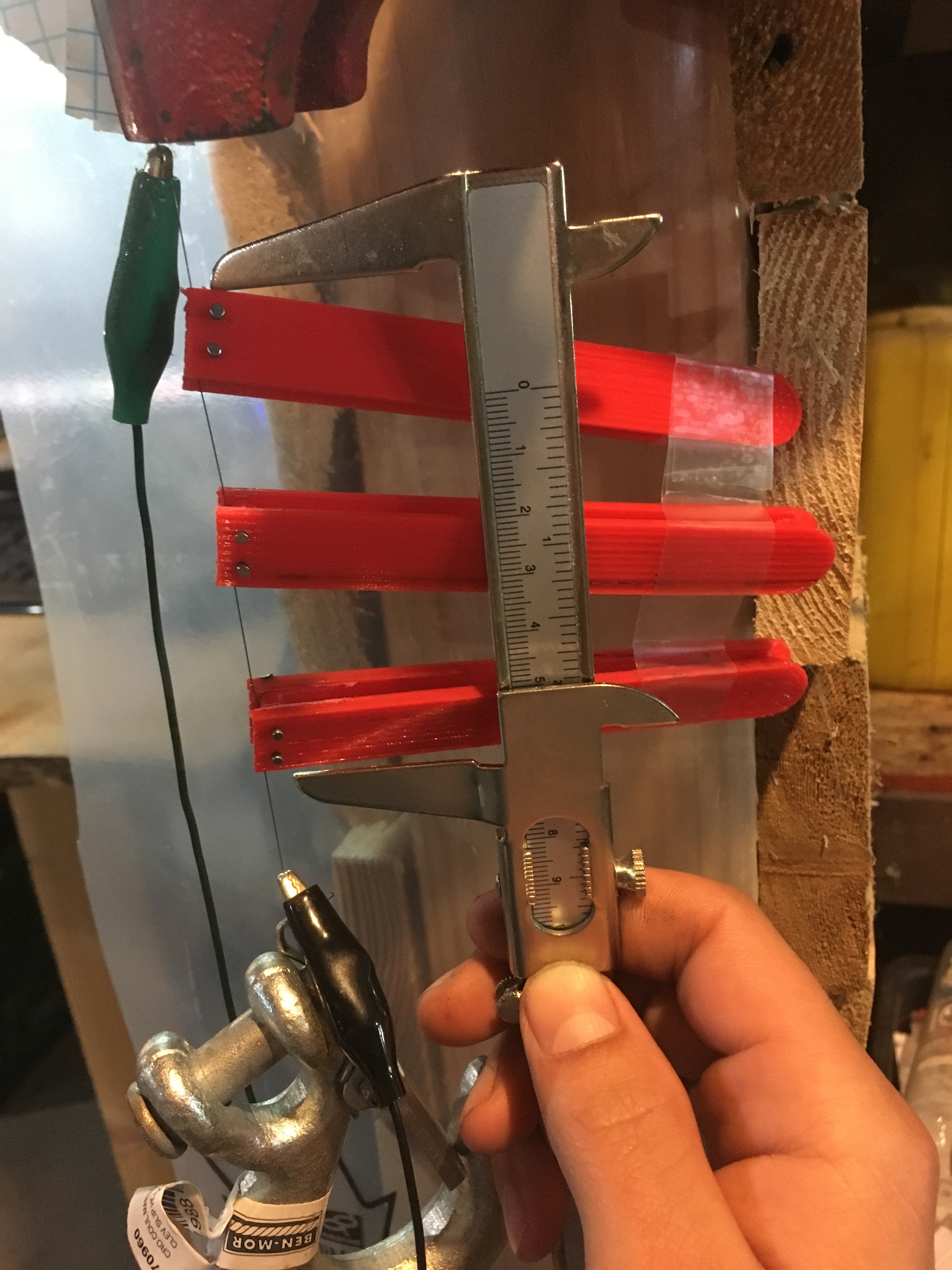
There was a lot of distance between the pulleys in the last test. In this test I moved everything closer together. The initial length was 6.6cm, and the activated length 4.6cm.
Again, the measurement ignores 50% of the stroke, so a 6.6cm unit delivered about 3cm of stroke, or a contraction of 45%, really good results.
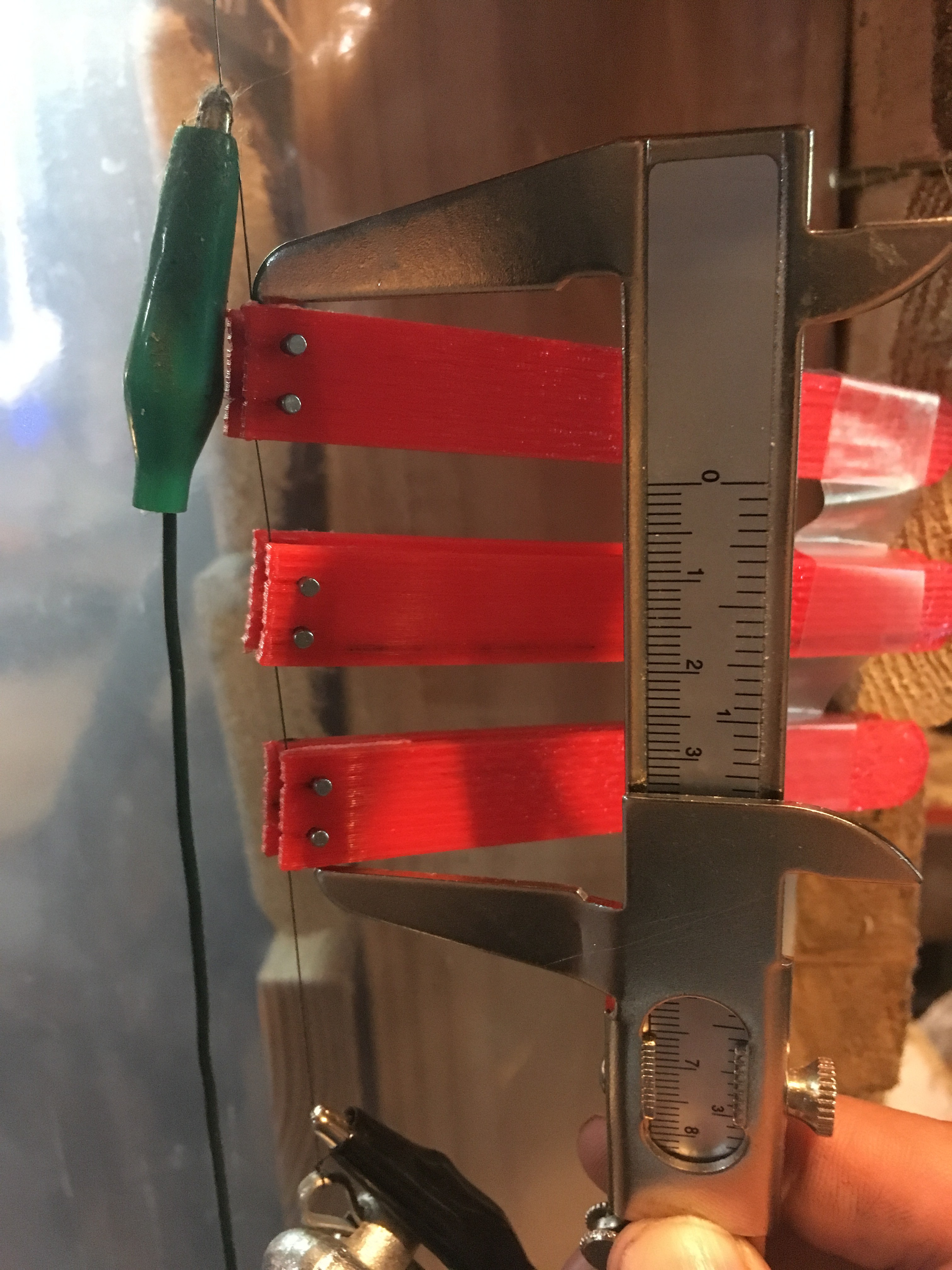
A successful run with a 3 pulley unit. The initial length of the assembly was 8.2cm, and it contracted several times to 6.1 cm, 2.1cm of stroke. This measurement ignores the stroke produced by the first and last pulleys, so the actual total stroke should be 50% higher, or about 3cm The hook swings around, making the measurement of the total stroke less accurate, but I measured 2.7cm.
The .25mm SMA wire I used is rated for a load of 891g.
The wire is travelling around the pulleys causing the assembly to twist around. The next prototype is going to have deeper pulleys and less clearance between the pulleys and the support.
My printer has some backlash on the X or Y axis, my circles are ovals.
Attaching the pulley system to the wire was not easy, lost a pulley in the process.
The support arm is bulky and ugly, probably way overbuilt.
PLA's plastic deformation point is 60-65C. The SMA wire has a transition point of 70C. I was worried that the wire would slice through the PLA pulleys very quickly, but after a dozens contractions there's no obvious damage. This is great as I'll be able to test with printed parts rather than printing, casting to high temp urethane, then testing. Casting parts is very time consuming, this is a big boost to the project.
The actuator with the zig-zagging pattern of SMA wire has a big, intrinsic disadvantage: the strain it can sustain without suffering permanent deformation varies throughout the stroke length. There's no way to work around this, the math sucks.
I've got another model that I've come up with that solves this, running the wire through two pulleys attached to long support arm. Using this setup I could run 60cm of wire, which will contract about 3 cm, between two points that are a few cm apart. As long as I can keep the pulley system compact enough, I should be able to reach the 30% contraction goal.
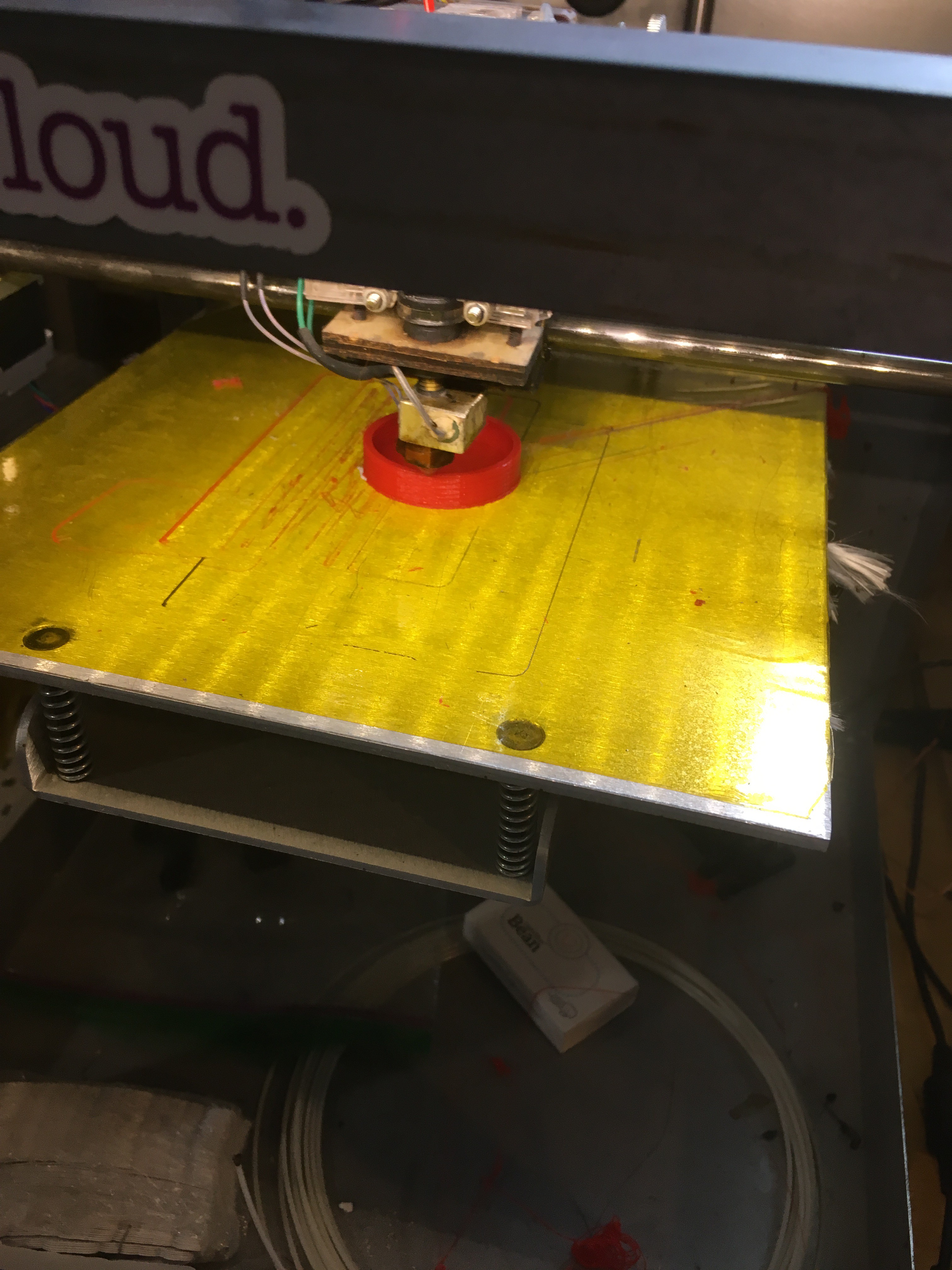
This I printed out and tested a prototype. The goal was to verify that the pulleys will spin and get a feel of what the end device will look like. It worked.
Building a jig to hold the small cross members is a pain, and the parts end up flying everywhere when the wire is tensioned. This time around I'm going to incorporate a support jig as part of the casting process. When the wire is attached to the cross members, the jig can be snapped off.

These guys make the most precise SMA actuators that I know of:
Very interesting, thanks., I knew about the basic principle but never expected applications beyond thermostats, or automatic beyond belief toasters...
 alexwhittemore
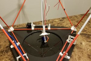
 MasterOfNull
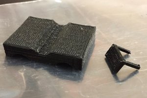
 Patrick
 Øystein
What about for short distances? Do you think you could get a decent resolution (~micron) if you could control the temperature relatively precisely?