-
Enclosure new 3d models
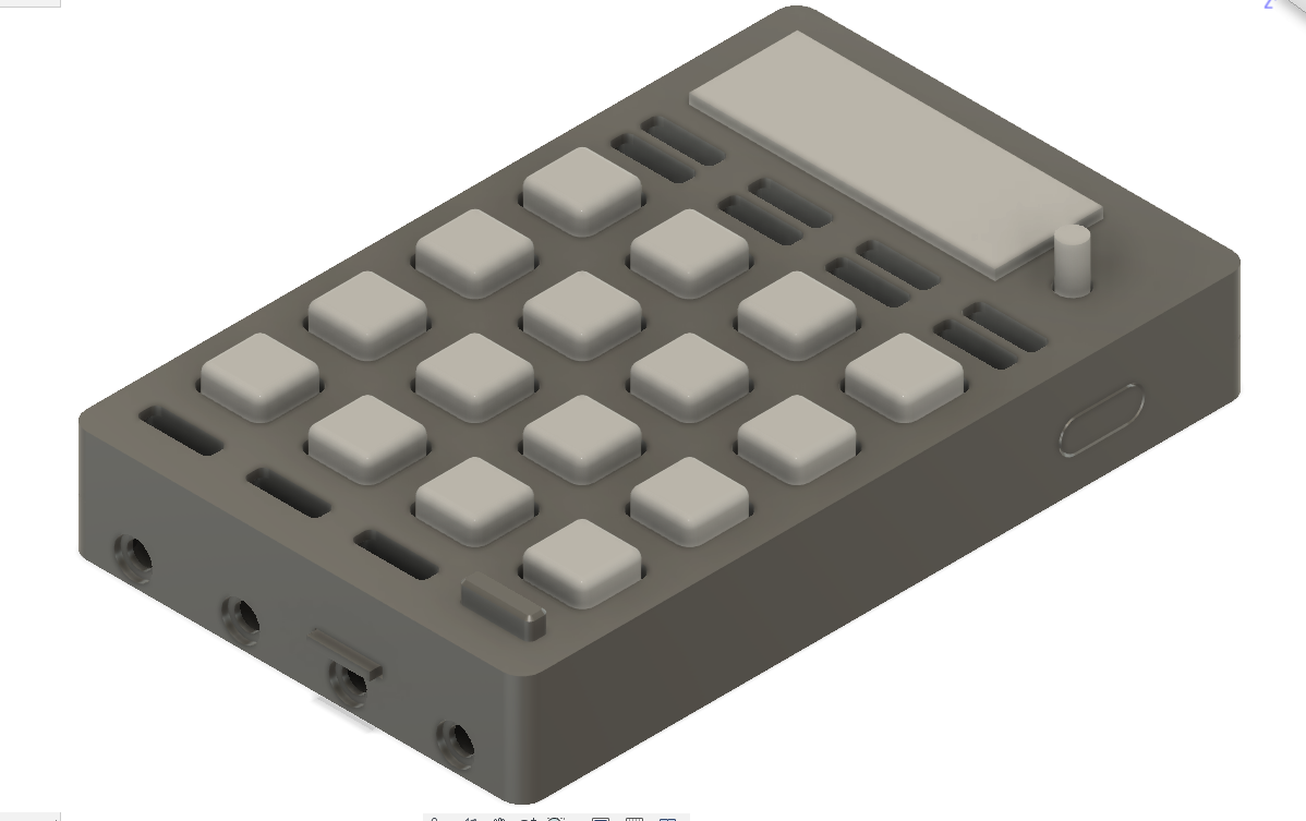
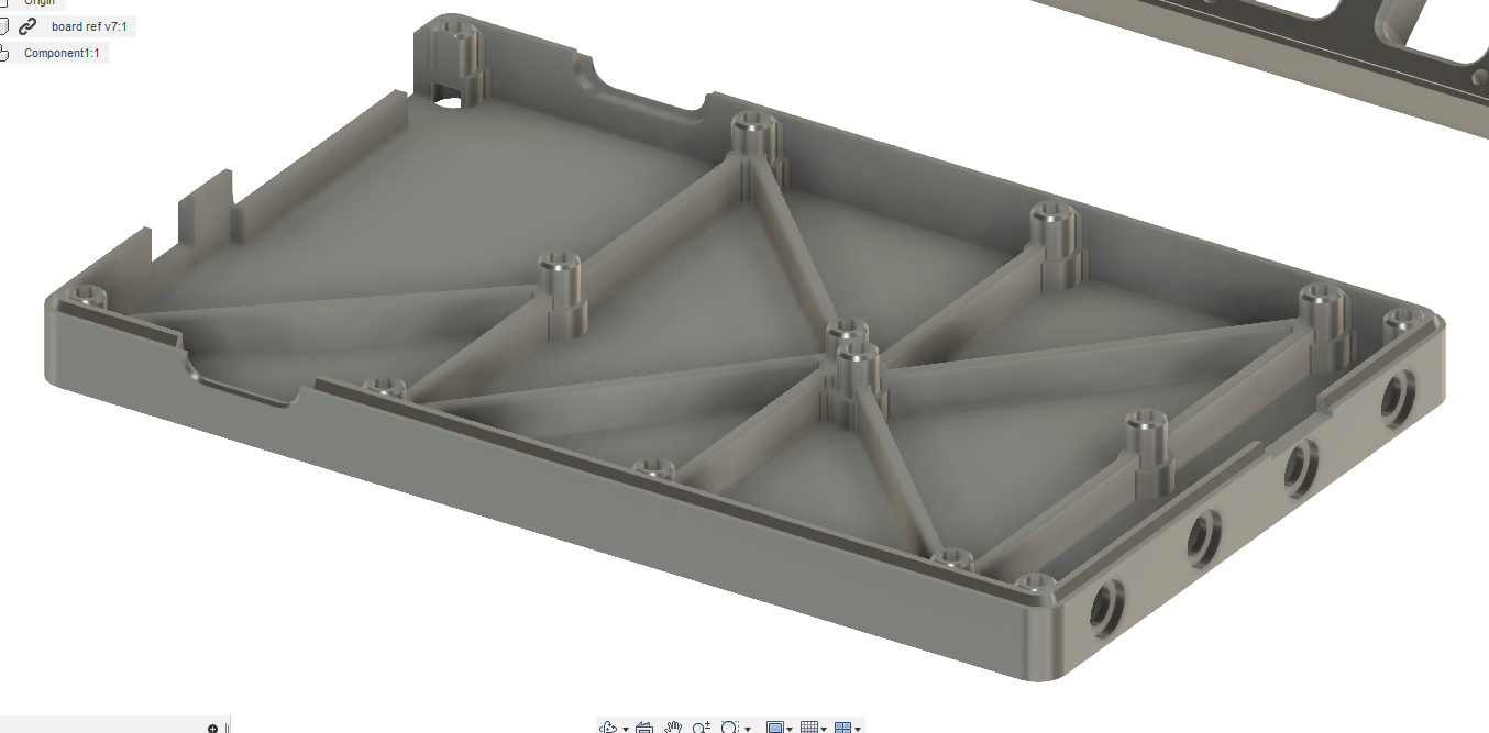
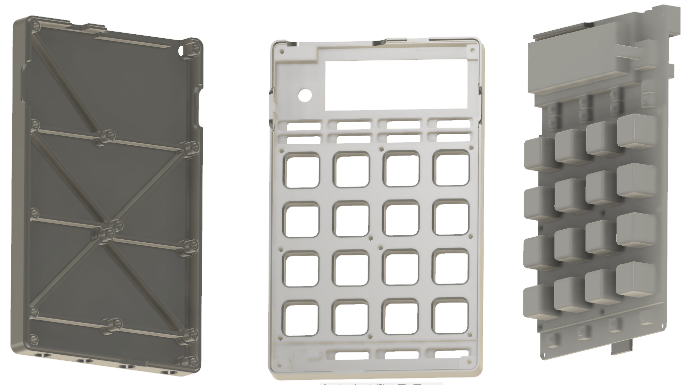
09/20/2018 at 13:54 • 0 commentsWhen I manage to get funding for this project, I'd like to make silicon casted enclosures for the calculeitor controller. Thanks to Aalto university, I am currently doing CNC milled enclosures so that it is possible to demo a more product-like presentation of this product. Here some pictures of the 3d models. Pictures of the finished enclosures might come later.
-
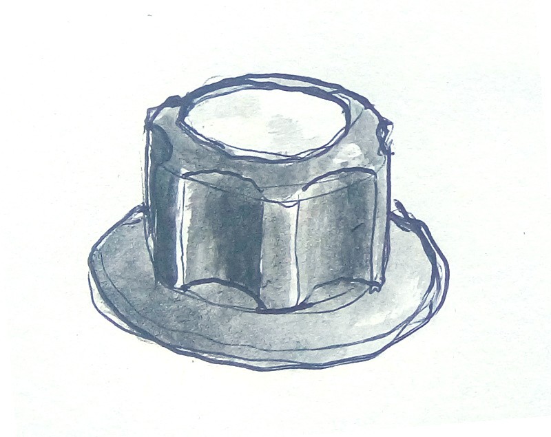
An essay about knobs
10/18/2017 at 14:48 • 3 comments![]()
I didn't know it was actually a topic, so I decided to write it down:
http://autotel.co/blog/an-essay-about-knob-design/
A 3d-print-able design will follow
-
Drafting building instructions with pictures
10/18/2017 at 08:04 • 3 commentsDrafting building instructions with pictures Here
![]()
-
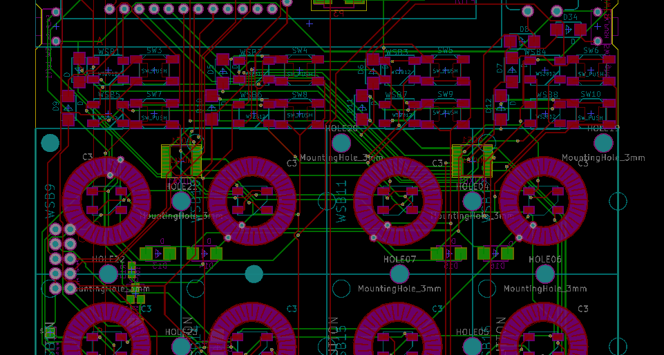
Working on a PCB update
09/18/2017 at 13:05 • 0 commentsThe current PCB design of this project requires the maker to put a couple of jumper wires. I want to make an updated PCB that additionally improves the following aspects:
- Brighter LED's using WS2812's instead of normal RGB LED's.
- Usage of 3 bits mux instead of 4 bits, ensuring easier supply.
- SMD components instead of through-hole, making the prototype a bit more eco-friendly, and scalable.
- Unuse the FTDI driver chip, making it cheaper
- More buttons for easier access of functions.
I started a repository that may be uploaded later.
-
2017 July: A virtually modular sequencer
09/10/2017 at 19:02 • 0 commentsWhen I departed to Japan I had the idea that in case I failed to do a modular sequencer in terms of hardware -meaning that one could patch modules by using cables, as in modular synths-, I would make a modular sequencer in a computer, that would be accessed through my hardware controller. As in Kyushu I started doing JavaScript prototypes for different models of sequencer modularity, I soon came into the realization that I could do a Node server that would hold the virtually modular sequencer. This would give me a great flexibility to tweak the interactions, and how the modular environment worked as I wanted. Over that, in the future, it would allow any other user to tweak my development and create their own modules; which is an extreme realization of my project intention. Perhaps this would allow a parallel culture of creating modules in my platform, like the one of eurorack modules, only that these would't need hardware.
The folder in the repository is "node_brain": https://github.com/autotel/thesis-prototype-zero/tree/master/node_brain
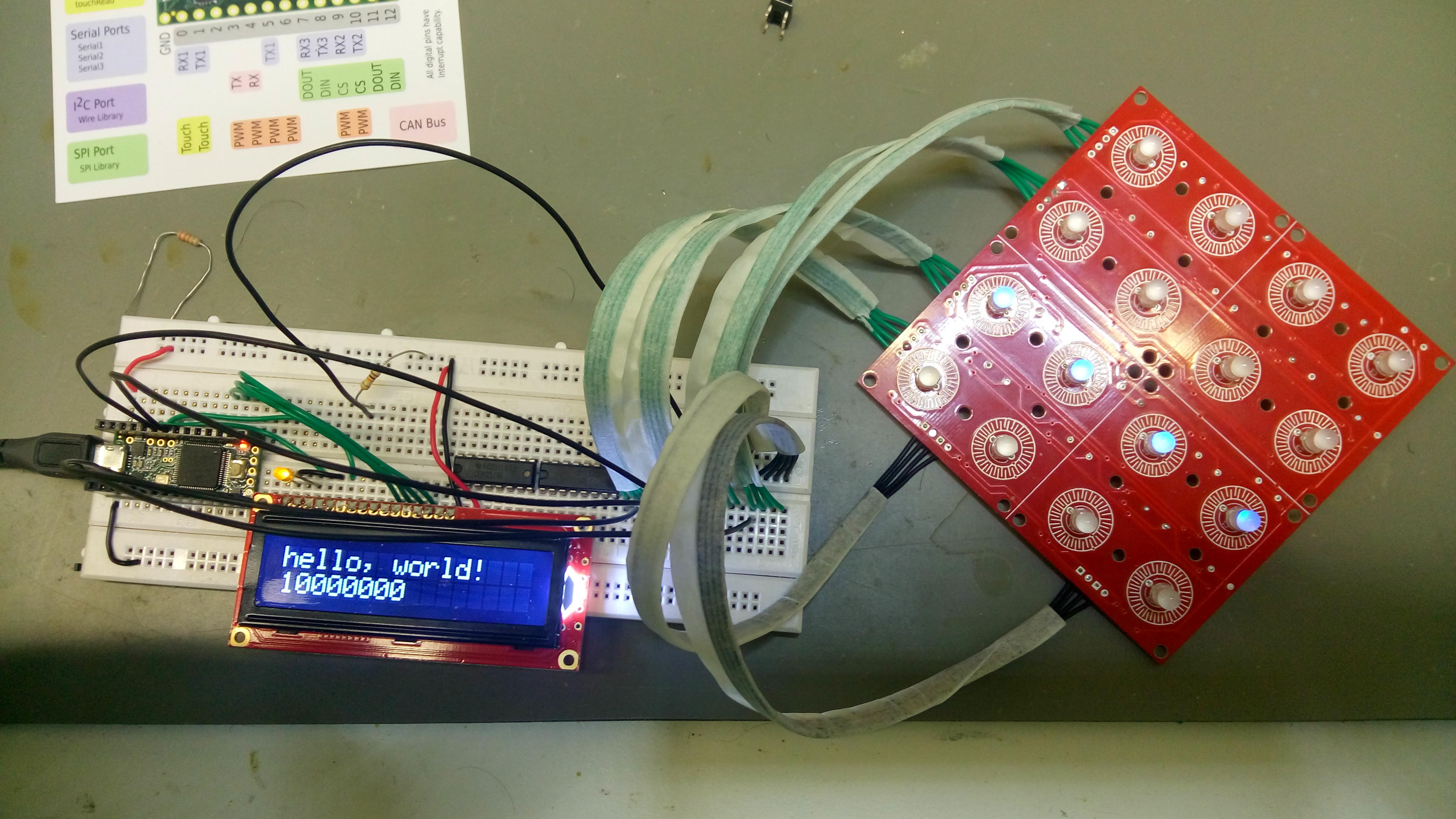
I bought a Raspberry Pi, and I reprogrammed the firmware of my interface, to get it working with a different pin mapping. I had to rewire only four pins in my prototype, and plug the raspberry to the serial port. Node Js had available libraries for all these functions:
- Express, httpServer, socket.io: I used these to make a server that I could use to display interesting visuals, in live performances. Just in case.
- jazz-midi: I used this to try midi functionality in windows. It doesn't work in the Raspberry.
- midi: this is the one that works in the raspberry. Sadly, the Midi input is still broken here.
- onhandlers: a simple library of my own to make custom events
- raspi: for peripheral support on the raspi
- raspi-serial: allows the raspberry to communicate with the arduino, which was now a human interface only
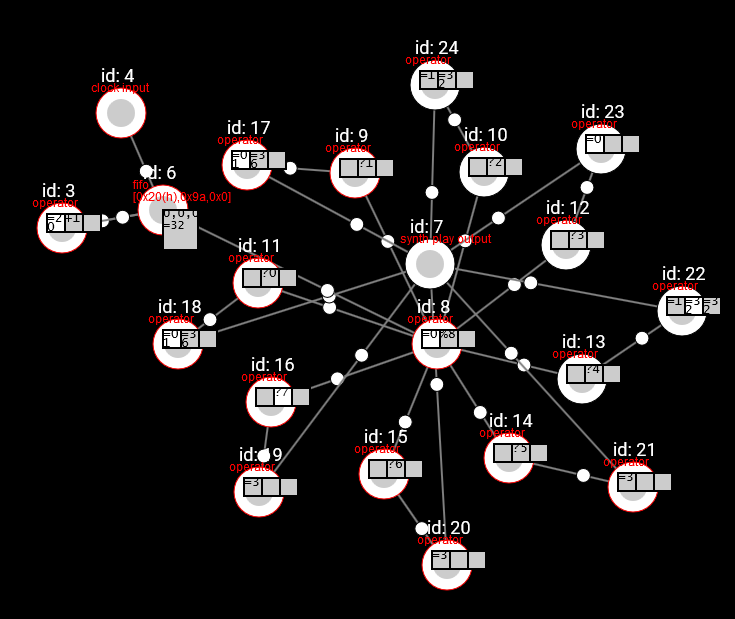
![]()
the visualization of the virtual modular sequencer in a web browser
there are some other libraries in the package.json simply because I haven't done a cleanup yet.
With this model, I could finally create a truly interesting tool for music improvisation. The user interface is still a bit cryptic, but with a bit of cleansing, I could do it understandable. There is some more detailed information of this exploration on this post.
me, playing live using my protoype
a closer look at how the virtual modular prototype works.
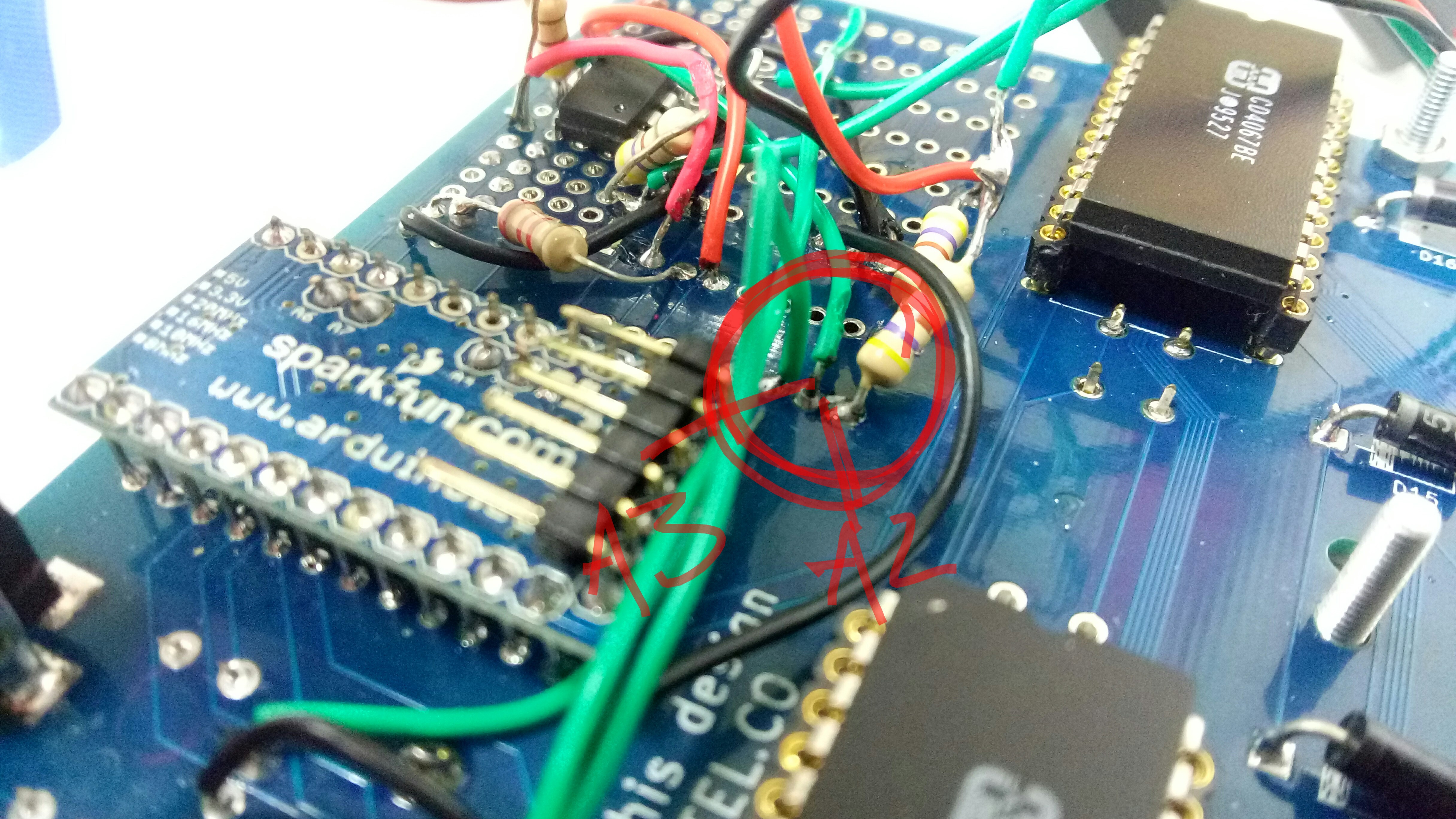
Given the design error that I described in the last update, this is how I needed to re-wire the manufactured PCB to make it work with the raspberry:
- PORTD 0 (RX): now is not soldered to the board
- PORTD 1 (TX): doesn't go to the board either
- A1 goes where PORTD 0 (RX) used to go
- A2 goes where PORTD 1 (TX) used to go
-
2017 may, Modular sequencer
09/10/2017 at 18:40 • 0 comments![]()
With regard to the starting point of my project, which is to enable improvisation of electronic music, I realized that I would benefit from using the concept of modularity, applied to the digital pattern sequencers. This happened by seeing how eurorack performances let musicians or sound artists to improvise. I wanted to harness this same power in the world of digital pattern.
This idea started in February. During November, December and January, I was struggling to fit all the functionalities that I wanted into the arduino pro-mini. I had seen that you can do 3d renders in TV screens, using this microcontroller, but there was nothing in my knowledge that I could do to shrink the consumption of processor time that my program was incurring in. https://github.com/autotel/thesis-prototype-zero/commit/a9413fb2c52825c5deaed022d47c6852d9ce6189 Perhaps I would need to know how to program in assembler. It was a better option to consider hardware changes. Check the commits during this period in my repository (here).
I tried first bringing a second arduino to the mix, one that would handle all the pattern memory, while the other would act as a display driver. During March, I went to exchange in Kyushu, Japan. There, I started revisiting the conceptual roots of my project, exploring further the idea of modularity. If I was going to make a sequencer system that can be patched to other sequencers or operators, I would need to develop some sort of language that would make sure that I don't get stuck in the future because I defined a protocol that is too specific to the modules that I was designing now. You can read more first here: http://autotel.co/2017/04/13/modular-sequencing-digital-prototype/ and second here: http://autotel.co/2017/05/03/sequencer-environment-design-experimentation/
While I was exploring the possible concepts of a modular pattern sequencer, I also started researching about how to communicate several micro-controllers, in order to achieve this modularity. It is not a simple topic; and to the date I have not done a proven solution, although I managed to make a modular sequencer product, as I will explain later. See some posts where I asked about this http://forum.arduino.cc/index.php?topic=479753 and here: http://www.avrfreaks.net/forum/possible-heterogeneous-common-bus-input-common-bus-output-protocol. I got very insightful answers, and I am currently working in this problem. When I finish with it, I will come back later to those posts to explain my final solution.
-
2016, november: firmware
09/10/2017 at 18:07 • 2 commentsI couldn't go deep into the design of the firmware until I had the manufactured PCB version of the prototype, because the contacts weren't reliable, and it was hard to debug wether something was not working because of a broken connection, or because a software problem.
My plan was to take the programmed prototype to different music nerds, and allow them to build their own sequencer and make their own transgressions to it. Specially because at that time I would be a week in new york, and then in Mexico, and after that in Chile. As from from Finland it takes about a month and a lot of money to get a shipment from U.S. suppliers (for the RGB led's and the so) I bought enough materials to make other nine of these modules while I still didn't have the firmware finished, and I would receive them in New York. In this way, I could make a workshop and receive influence from other makers in many parts of the world.
Once I started developing the arduino hardware, it was easy to get the hardware to work right. I could also do some simple user interfaces such as a midi drumkit (like the korg padKontrol) or a simple 16-step sequencer.
The led's are turned on one by one by the microcontroller. Each led leg is connected to one multiplexor output, and each button aswell. The firmware is constantly scanning the two multiplexor addresses and giving a voltage or not, according to wether each led must be on or not.
//update one pixel on one of the color channels behind the mux. Be aware that redPixel function exists void updatePixel(byte currentPixel) { currentPixel += 0xf; //nibble A is connected to the mux address for the anodes / btn inputs byte nibbleA = 0xF; //nibble B is connected to the mux for the cathodes / btn outputs byte nibbleB = 0xF; byte currentLayer = currentPixel / 16; if ((layers[currentLayer-1] >> (currentPixel % 16)) & 0x1) { //(currentPixel>>2)&12 is the same than doing floor(currentPixel/16)*4. try it in codechef nibbleA &= (currentPixel % 4) + (currentPixel >> 2 & 12); //[0-15]=0,[16-31]=4,[32-47]=8,[48-63]=12 nibbleB &= (currentPixel / 4) % 4; //~0x10 << ((currentPixel / 4) % 4); //0,0,0,0,1,1,1,1,2,2,2,2,3,3,3,3, will happen 4 times within 64 loop nibbleB += 8; //ground & power the led. strangely still works without these lines digitalWrite(analogA, HIGH); digitalWrite(analogB, LOW); PORTD = (nibbleB << 4) | (nibbleA); switch (currentLayer) { #if COMPENSATE_R > 0 case 3: delayMicroseconds( COMPENSATE_R); break; #endif #if COMPENSATE_G > 0 case 1: delayMicroseconds( COMPENSATE_G); break; #endif #if COMPENSATE_B > 0 case 2: delayMicroseconds( COMPENSATE_B); break; #endif } } } //just draw a pixel disregarding the layer information void turnPixelOn(byte currentPixel) { //nibble A is connected to the mux address for the anodes / btn inputs byte nibbleA = 0xF; //nibble B is connected to the mux for the cathodes / btn outputs byte nibbleB = 0xF; byte currentLayer = currentPixel >> 4; //(currentPixel>>2)&12 is the same than doing floor(currentPixel/16)*4. try it in codechef nibbleA &= (currentPixel % 4) + (currentPixel >> 2 & 12); //[0-15]=0,[16-31]=4,[32-47]=8,[48-63]=12 nibbleB &= (currentPixel / 4) % 4; //~0x10 << ((currentPixel / 4) % 4); //0,0,0,0,1,1,1,1,2,2,2,2,3,3,3,3, will happen 4 times within 64 loop nibbleB += 8; //ground & power the led /*PORTC |= 0b1; PORTC &= ~0b10;*/ PORTD = (nibbleB << 4) | (nibbleA); }This worked nice, but led to the problem that, the more the microcontroller was doing, the lower that the led's refresh rate would be.
I started experimenting a bit more with the interactions, to make more interesting transgressions to my initial 16 step sequencer; but I couldn't make any longer sequences. These were my mistakes:
- I wanted to use a whole port to address the multiplexer, and use the analog inputs to detect the button presses, as to be able to detect pressure. I used PORTD. This meant that I didn't have a hardware Serial port, and thus, with a more complex code, the MIDI started lagging in time and generating hanging notes. And yes, I became a magician of debugging without Serial.
- Reliance on persistence of view for the LED's works, but the more complex the program gets, the lower the refresh rate. When I started having a decently interesting sequencer, the LED's were flickering really bad, and it got hard to use if there was too much ambient light.
My sequencer transgression workshop would have to wait a bit more.
-
2016, October: First physical prototype
09/10/2017 at 17:47 • 0 commentsI started, ending last year, to create a physical controller to explore my idea of making a tool for improvisation of electronic music. I didn't have very clear all the theoretical aspects of what I was about to start, but I knew that I had a strong discontempt about the current tools for music performance. At this point I was playing live using Maschine and Korg Electribe.
My first idea was to start creating a sequencer, which for me is the most basic unit for single-man bands. Loopers are the other candidate, but as I wanted to work with musical mutation of the patterns, I thought that sequencers were a better starting point. Also sequencers are much easier to make and tweak since you can output midi events, instead of needing to create analog<-> digital conversions, or having to work deep in DSP.
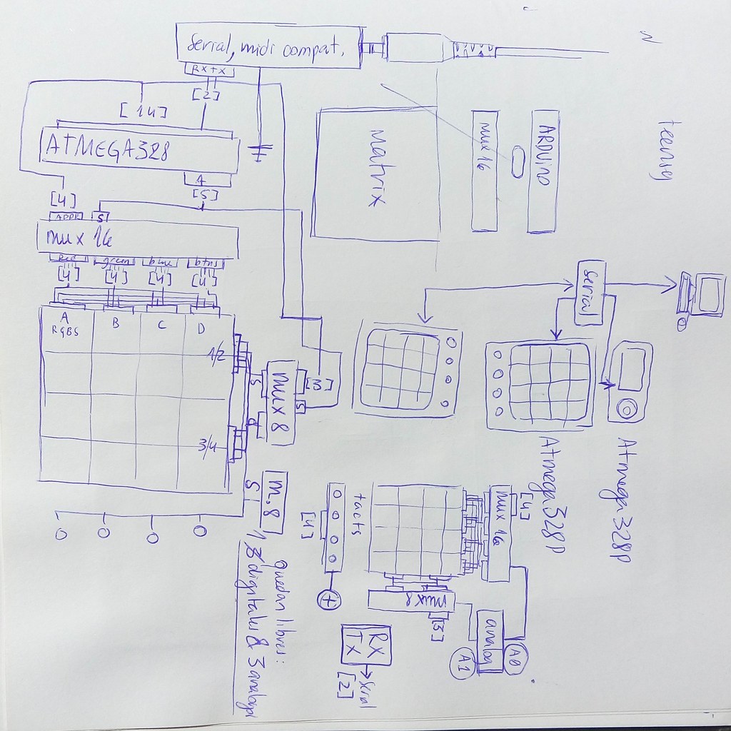
This prototype was soldered in prototype board, using parts from SparkFun. It never worked really well in the proto-boards, because of the amount of cabling that involved. However, I could figure out the schematic that would work, in order to design it in KiCad.
![]()
I started using Teensy microcontroller, but I had some trouble writing bytes to the pin ports, and I discovered that when you do a PORTD=something, it maps each byte to a digitalWrite. I know that Teensy has a great processor power, but I found that just too horrible. This, added to the fact that you can't buy the Microcontroller from other supplier because the firmware is not opensource, I decided to use Arduino instead. This ment that instead of using 8-bit multiplexor for the LED's, I needed ones of 16 bits. I discovered that their DIP version is no longer manufactured, but thankfully, Bebek store in Finland had a huge stock. They look really nice, in big, retro package.
The repository I started working in, is now in https://github.com/autotel/thesis-prototype-zero
I tried many different configurations between the microcontrollers and the multiplexors. The best schematic is in the folder thesis-prototype-zero/kicads/try1/ of the repository. Open the version with DIP muxes.pro file of that folder; there you will find the schematic and the PCB layout as well.
![]()
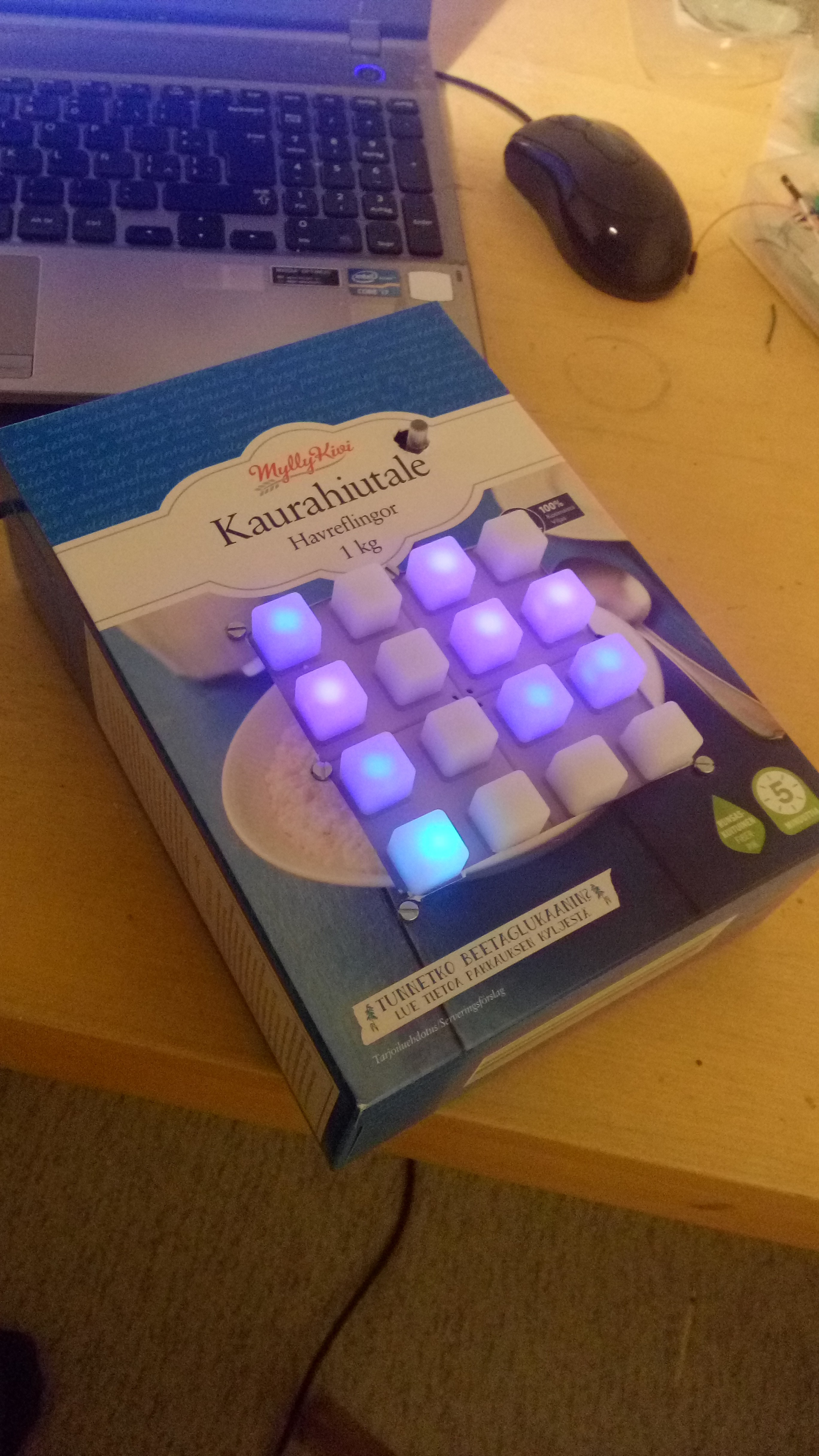
This was the first enclosure I used:
![]()
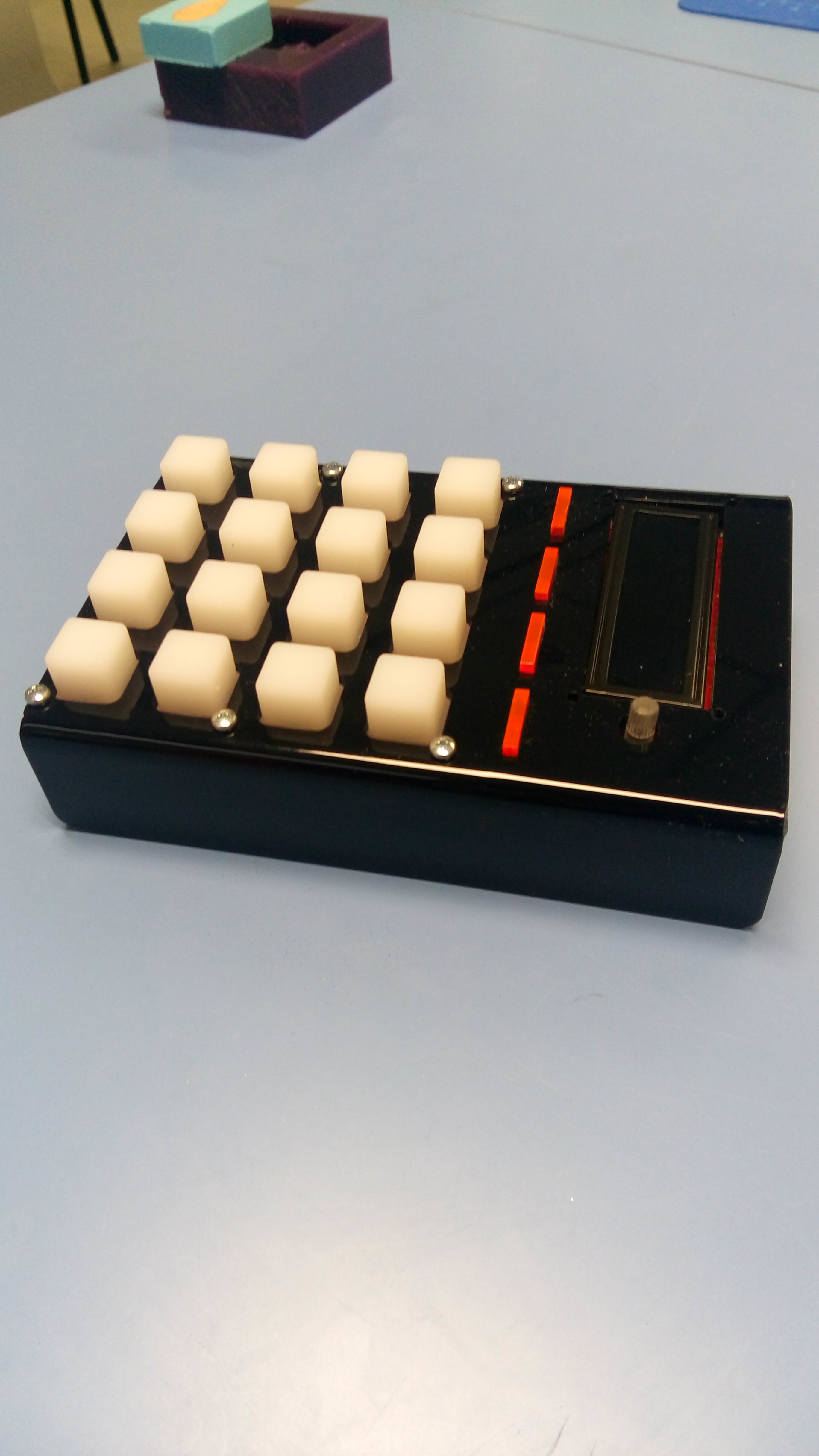
With a bit of time, I did a better enclosure for the soldered prototype. It is nothing more than a bent acrylic:
![]()
Then, I designed a board on Kicad and had it done
![]()
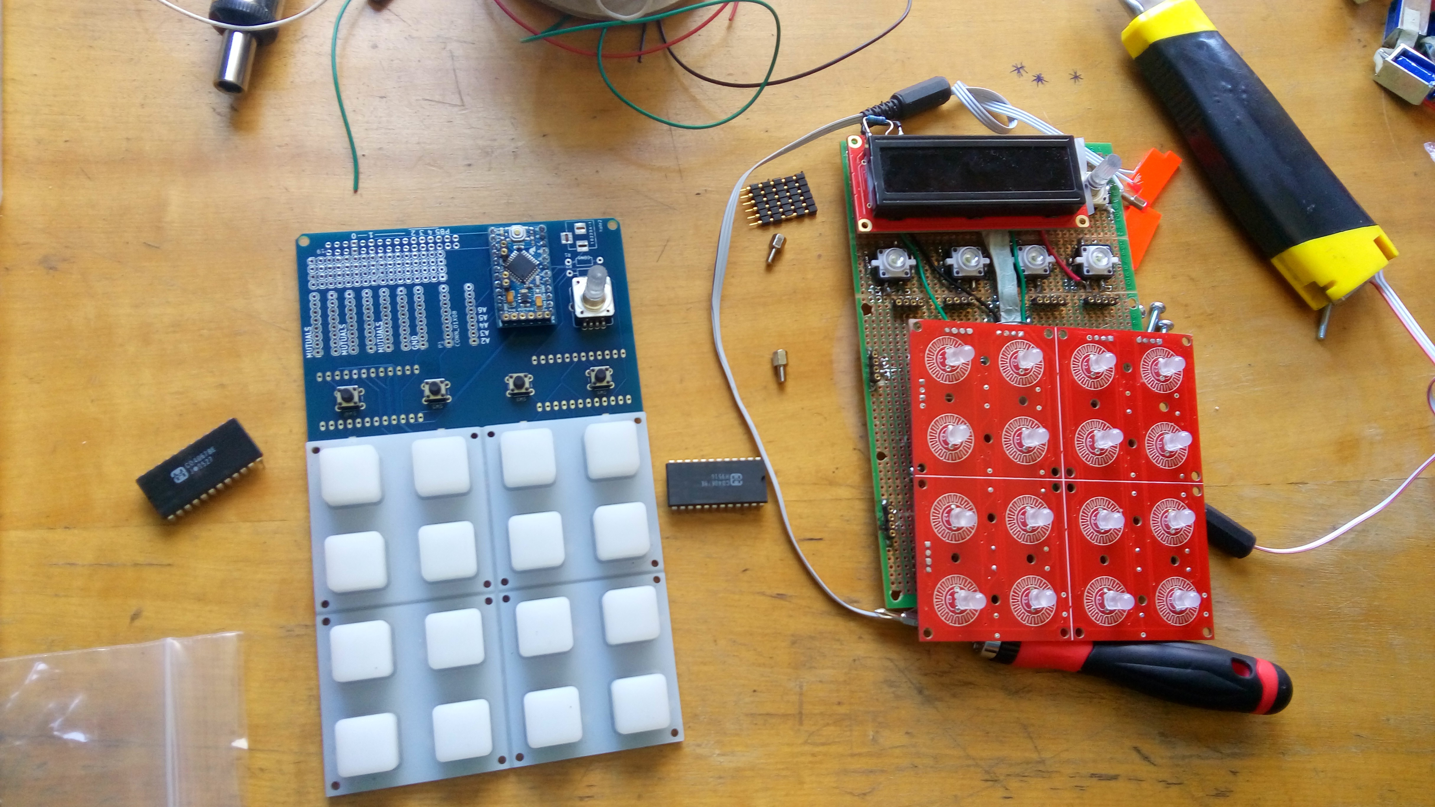
Seethe solder-protoboard and the manufactured protoboard side by side:
![]()
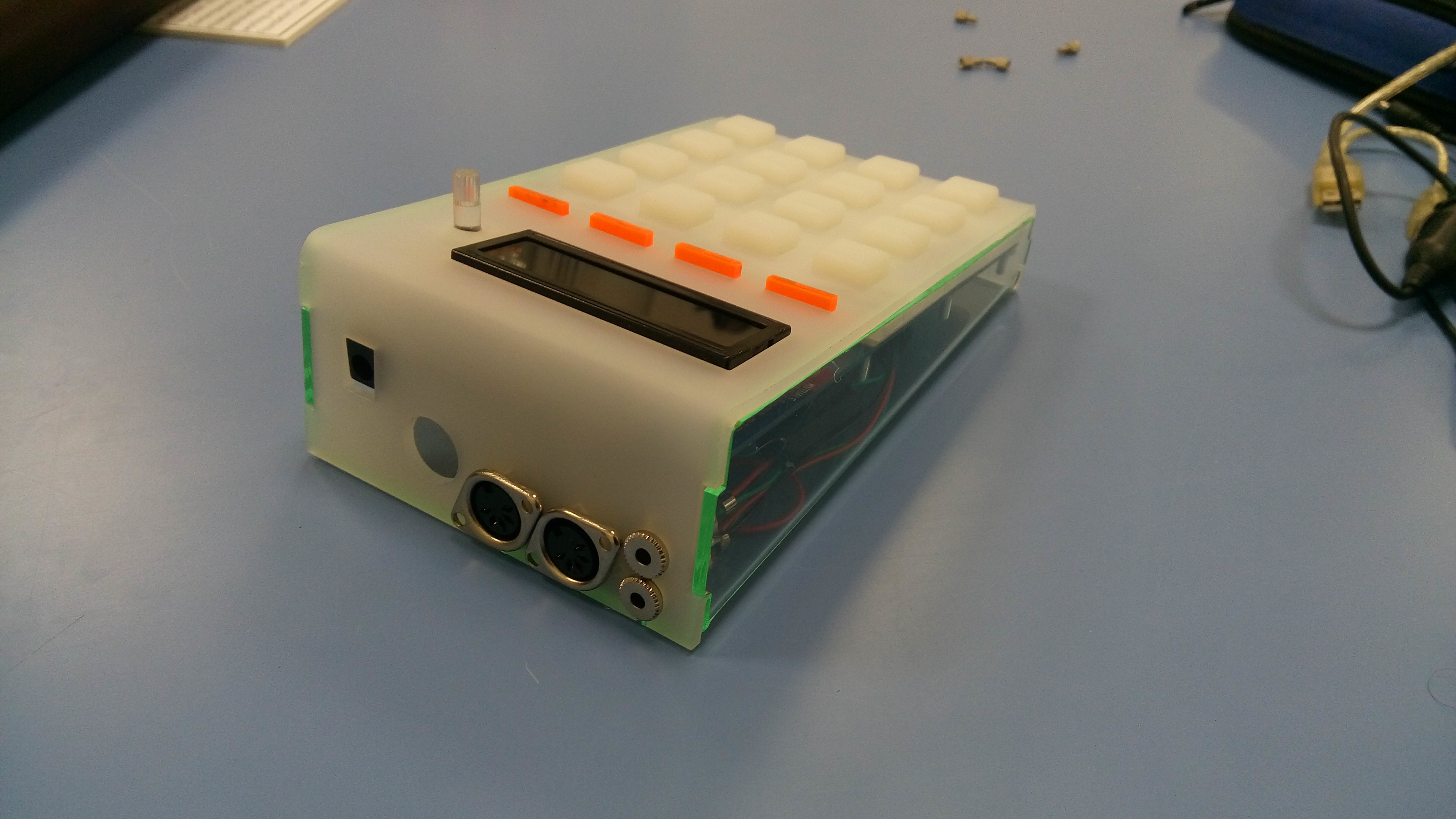
This is the enclosure for the pcb-based prototype. I added midi input and output, plus the respective midi-jack connectors. I ran into the problem that Korg devices have a different pin map for jacks than all the other manufacturers of midi jacks.![]()
see a video where I test how these buttons can sense pressure and serve for nice sound expressions:
A modular sequencer for electronic music
A sequencer that offers the possibility to be connected modularly and musical operators to build up more complex live electronic music.