Blecky
-
PCBs Have Arrived!
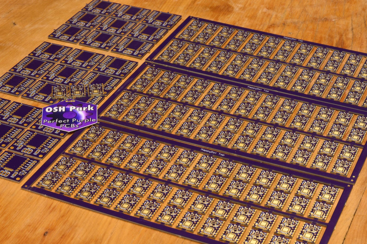
08/17/2017 at 09:32 • 2 commentsThe panelised MappyDots have arrived from OSHPark and they are beautiful!
I also have to give a BIG thank you to Drew and Dan from OSHPark, their help and support have been immensely valuable!![]()
-
Release Date
08/12/2017 at 13:46 • 2 commentsJust a heads up, the MappyDot should be in stock on the Tindie store around the end of this month. The ATMega328PB MCU's have been out of stock for a little while worldwide, with a long lead time. However I have managed to secure quite a few of them to get the ball rolling.
The product page is now online if you would like to add the MappyDot to your wish list.
The firmware for the MappyDots is about 90% complete, with just a few little features to test out and tweak. The sources will be released at the same time the MappyDots become available for you to peruse. A Fritzing part is now available in the repositories.
![]()
-
SensorDots Website
08/06/2017 at 15:56 • 0 commentsIn preparation for the sale of the MappyDot in a few weeks on Tindie, I have created a new website to house some of the content.
Most of the sensor information and documentation will now reside on this site. However, I will still continue to release technical project logs on hackaday.io for those that prefer the nitty gritty details.
Be sure to take a look and let me know if there are any issues or if there's anything you don't like :)
![]()
-
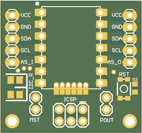
Development Board
08/05/2017 at 05:06 • 0 commentsI have created a breakout development board for the MappyDot to help people develop different applications. It brings out the ISP programming headers and has a reset button, master select jumper, optional I2C resistors and mounting holes. This is an easier to use alternative for development, than just creating an adapter for the ISP pins.
![]()
![]()
The dev board gives you the option to either connect headers to the MappyDot boards for easy removal, or to solder the MappyDot directly to the board.
The dev board schematic and production files are located on the git repo - https://github.com/MappyDot/Hardware/tree/master/MappyDotDevBoard. Or available here on OSHPark. They will also be available for sale with the MappyDots as a kit with headers.
-
I2C Firmware Updates
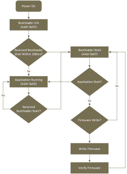
08/03/2017 at 07:58 • 0 commentsJust a quick one to let you know that the I2C firmware updates are now working on the MappyDot. The software flow of the MappyDot firmware update proceedure is as follows:
![]()
The bootloader loads first on startup and waits for a bootloader start message on I2C address 0x07 for 200ms. This is a safety feature that allows you to recover modules with a bad flash or modified firmware that prevent it going into bootloader mode while running. You can power cycle the chip by briefly shorting the reset pin on the MappyDot if it is hard wired in to a bus. If you have multiple MappyDots on a bus that aren't functional, you can hold the reset line low on all of them and just do one at a time.
When the application is running, you can enter the bootloader to enable flashing at any stage while it's operational using it's auto addressed I2C address. Once it boots into bootloader mode, it switches to I2C address 0x07 for the bootloader process. The programming software automatically changes this address for you during the firmware flashing process.
The programming software works with any standard Linux I2C device, such as /dev/i2cX on the Raspberry Pi's Broadcom chipset. If you don't have an I2C device, or are using Windows, there is also an Arduino I2C->USB adapter sketch you can use to load the firmware with, which the application supports.
Here's the output from the software:
twiboot-arduino -a 0x08 -d /dev/ttyS4 -w flash:MappyDot.hex
device         : /dev/ttyS4       (address: 0x08)
version        : MDBOOT328PBv2.1  (sig: 0x1e 0x95 0x16 => ATmega328PB)
flash size     : 0x7c00 / 31744   (0x80 bytes/page)
eeprom size    : 0x0000 /     0
writing flash  : [**************************************************] (9642)
verifing flash : [**************************************************] (9642)
If the firmware fails to verify, you can run the flash operation again. If you power cycle the MappyDot after the firmware fails to verify, or you load a modified firmware that doesn't support the bootloader mode command, then you can always recover by entering the bootloader during startup of the MappyDot.
-
Designing a Filter
07/23/2017 at 04:38 • 0 comments![]()
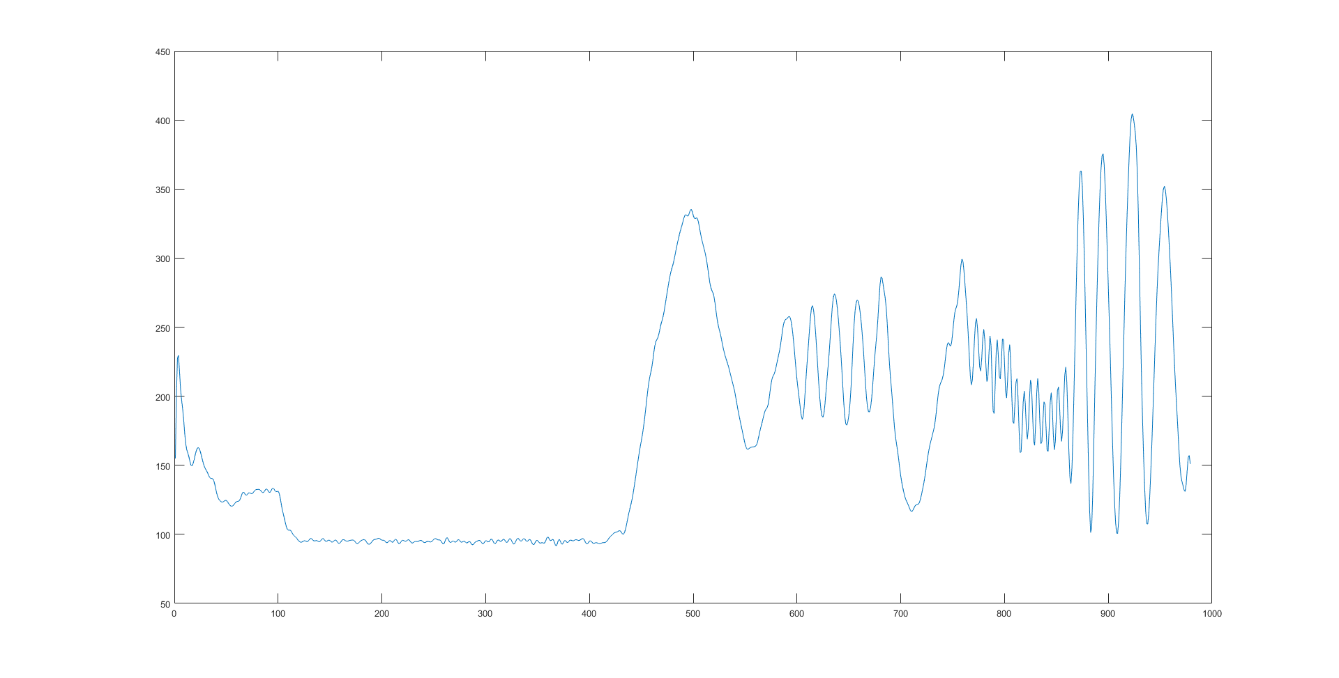
Like any sensor information, there will always be some inherent noise associated with the output data. This is practically unavoidable as anything that has free flowing electrons will have an associated thermal noise with it, among other sources. This is the main reason why you get grainy images on a digital camera at low light values.
So how do we deal with it. The first and easiest method is to just ignore it and move on. However, these higher frequency effects can play havoc with some control system. If you look at the MappyDot's raw data output from some still, medium and fast motion (measurement rate of 30Hz), you will see many higher frequency "spikes" on the data, which if used on robotics, can be translated into large acceleration values if you don't account for it on a smaller timescale (by filtering):
![]() To help with this, each MappyDot will by default actually do some of this filtering for you which reduces the processing overhead required to filter data from numerous sensors at once for general and rapid motion cases. You can turn this filtering off on the MappyDot if you want higher frequency motion data.
To help with this, each MappyDot will by default actually do some of this filtering for you which reduces the processing overhead required to filter data from numerous sensors at once for general and rapid motion cases. You can turn this filtering off on the MappyDot if you want higher frequency motion data.
To do this, we first needed to design a filter that would be both useful and not lose too much information. We want something that can limit any higher frequency effects as they arrive into the system. Limit here being the key term, as it will smooth incoming data and still maintain "lower" frequency response.If we look at the FFT of the dataset, we can see that after 5-6Hz, there is no significant changes apart from noise:
![]()
Using Matlab, we can create a simple low pass filter to help cut off these values and to analyse the changes made by changing certain coefficients. This won't be the final design of the filter implementation as it needs to work realtime, however we can play around with this to optimise the cutoff frequency for decent looking results.
filename = '..\filtering_raw_data';
A = importdata(filename);
clf
hold on
plot(A)
fNorm = 3 / (30/2); %3Hz cutoff frequency, 30Hz sample rate
[b, a] = butter(10, fNorm, 'low'); %Butterworth filter with order 10
Y = filtfilt(b, a, A);
plot(Y);
Note that filtfilt "performs zero-phase digital filtering by processing the input data, x, in both the forward and reverse directions". So the actual implementation will have a small delay depending on the order value since we don't know the complete waveform as it comes in. This delay however can be exceptionally small (~<33ms), so it shouldn't affect the output so much if the filter is turned on. And since this is performed on the MappyDot, if you are reading this data at a slower rate (<30Hz) with another device, this delay will not be noticed. Some more reading here and here.
---------- more ----------0.3Hz cutoff (really bad fit, most information lost):
![]()
1Hz cutoff (getting better, still loss of information):![]()
3Hz cutoff (much better fit, but fast motion is still cut off):
![]() 4Hz cutoff (similar to 3Hz):
4Hz cutoff (similar to 3Hz):![]()
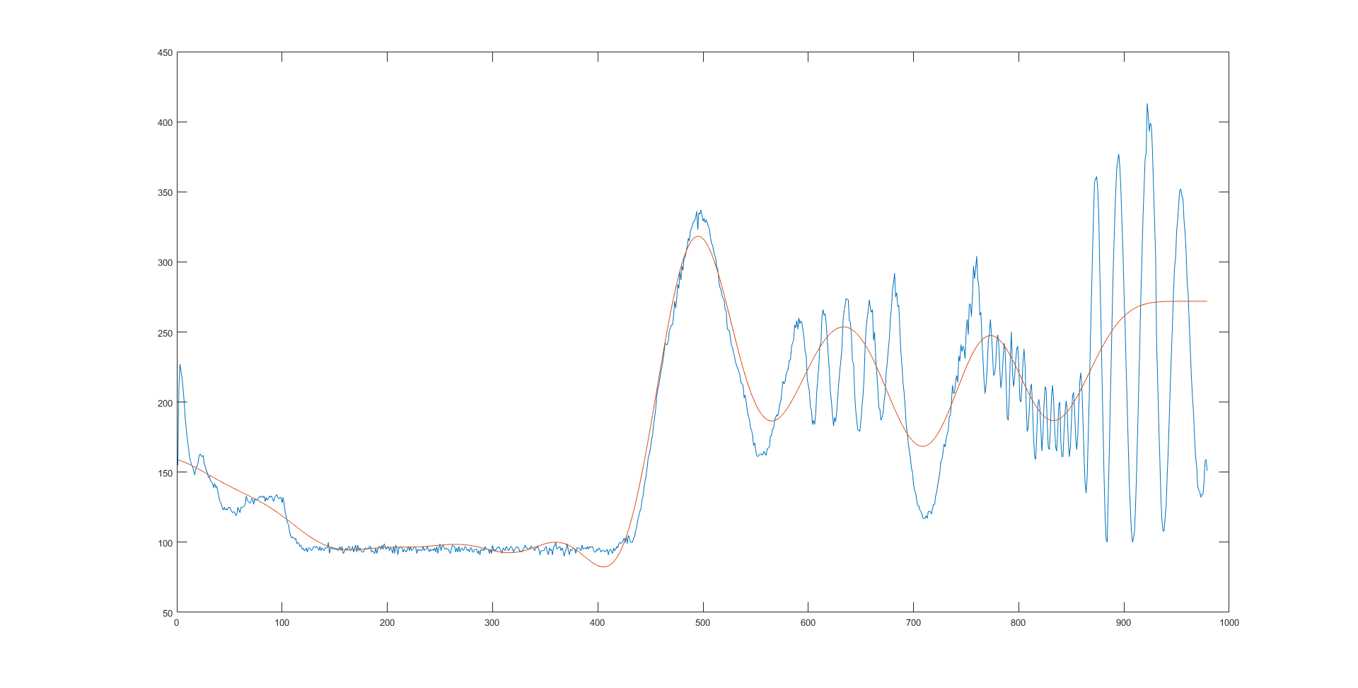
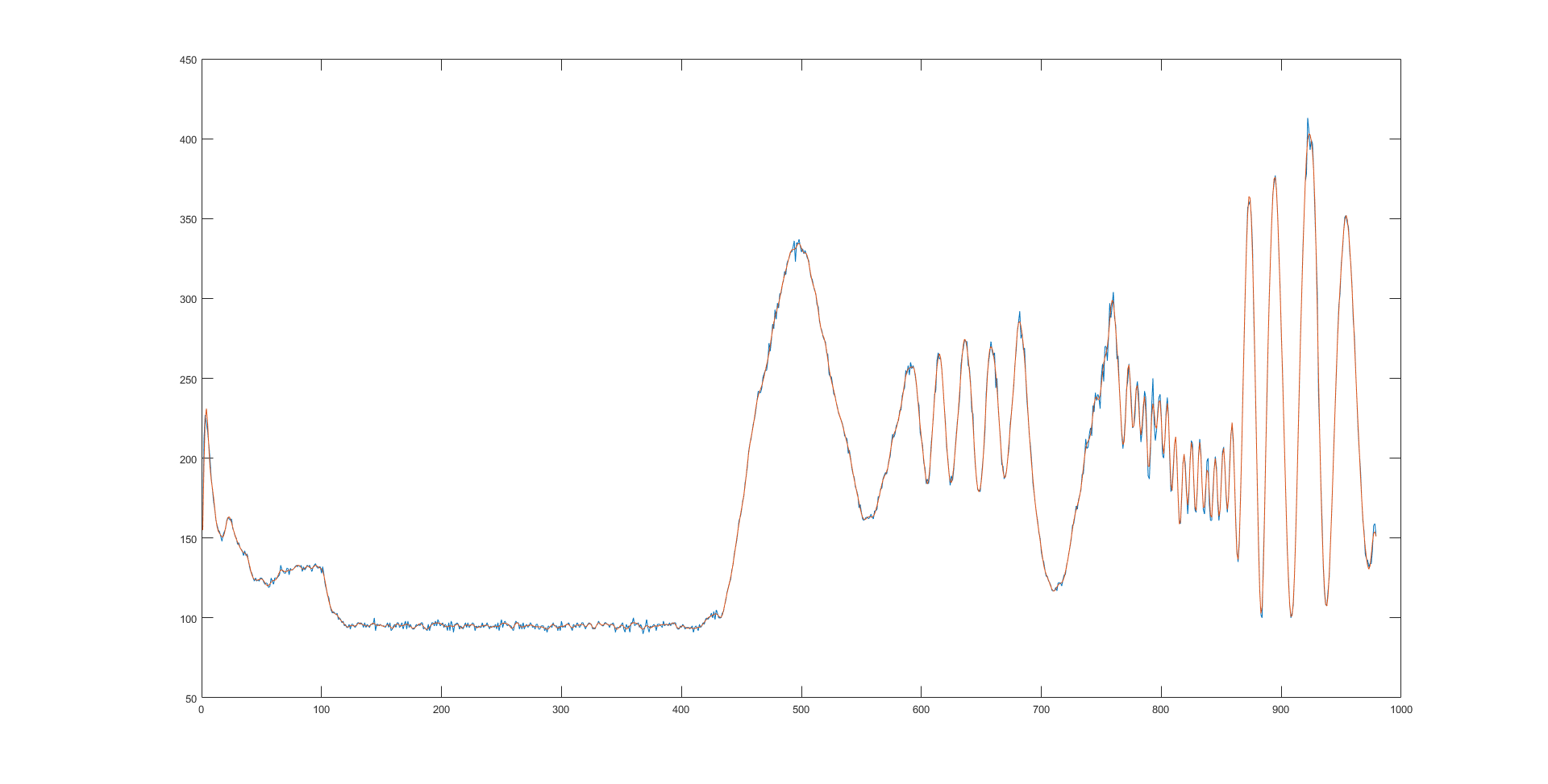
5Hz cutoff (much better fit with faster movements, although there is still some bad fitting, high frequency noise effects are cutoff):
![]()
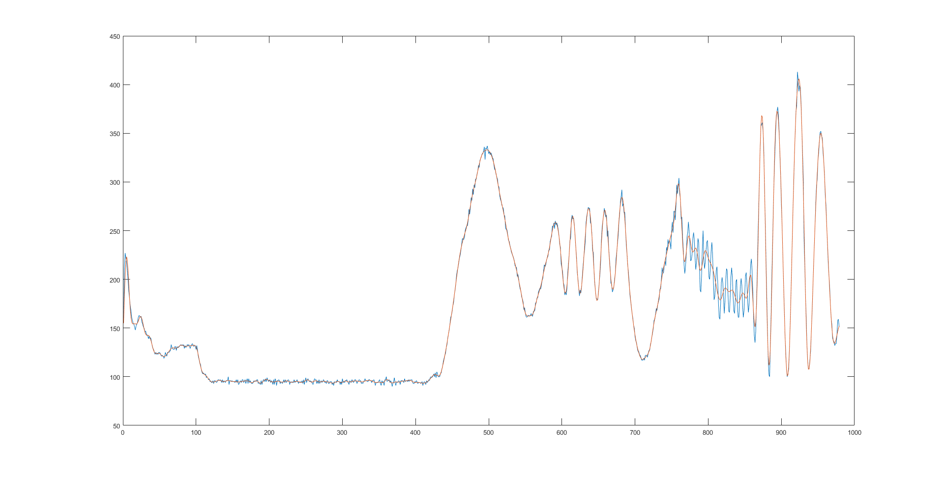
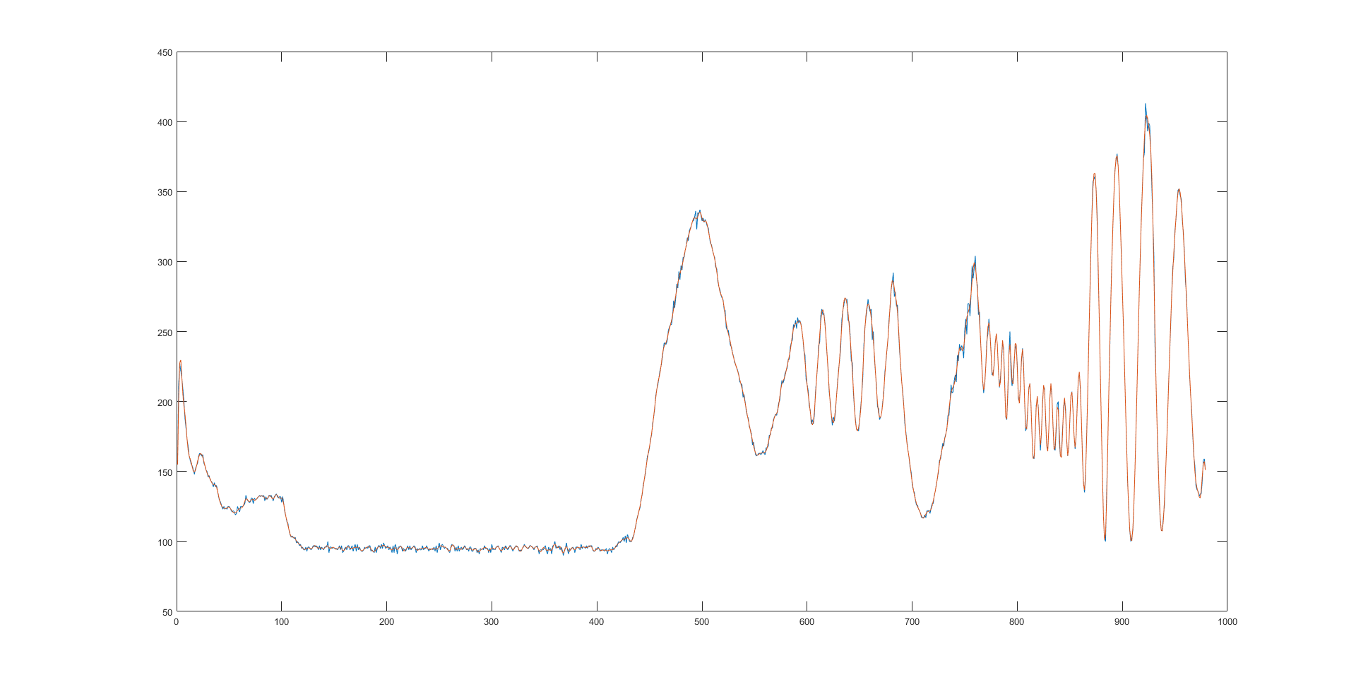
6Hz cutoff (very good fit for faster movement, high frequency effects are still smoothed out):
![]()
And if we look at the 6Hz cutoff by itself:
![]() If you compare that to the original data above, you will see that you get a pretty good representation of the data without too much information loss. Going much higher than 6Hz causes the data to start to fit to the higher frequency "spikes".
If you compare that to the original data above, you will see that you get a pretty good representation of the data without too much information loss. Going much higher than 6Hz causes the data to start to fit to the higher frequency "spikes".![]()
-
MappyDot Addressing
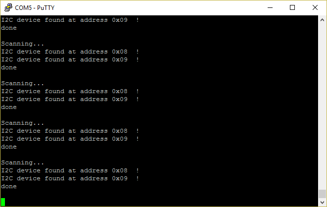
07/22/2017 at 13:36 • 0 commentsOne of the core features behind the MappyDot is the ability for devices in a chain to automatically assign addresses to each of the devices.
![]() When the MappyDot switches on, all devices go into a discovery state and wait until they receive an address command. All except for the first in the chain which is the master. The master will first assign it's own address as 0x08 and then initialise the address protocol:
When the MappyDot switches on, all devices go into a discovery state and wait until they receive an address command. All except for the first in the chain which is the master. The master will first assign it's own address as 0x08 and then initialise the address protocol:![]()
This address protocol is very simple and is based on the 1wire interface. The master sends the next address to be assigned, the slave then responds with what it thinks its address is then the master will ACK with 0x01 if this is correct (or NACK with 0xFE). If there is a NACK, the master and slave will retry. If there are too many retries, then they will blink an error code.
Once the slave has got its address, it then begins this process with the next device in the chain while acting as the master.
So if you now scan, you should see all the devices in the chain (after a few ms depending on the number of devices).
![]()
But what if you want to change the address range of the devices, instead of starting at 0x08? Well, that's simple. All you need to do is connect the ADDR_IN pin of the first device in the chain to your microcontroller, and initiate the addressing process with the start address you desire.
Because it is based on 1 wire, you just perform the 1wire detect presence procedure. If there is presence, then send the address, wait for the response, check that the address matches and send 0x01 for ACK or 0xfe for NACK.
-
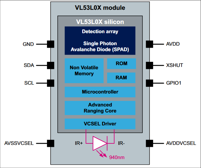
Inside a VL53L0X
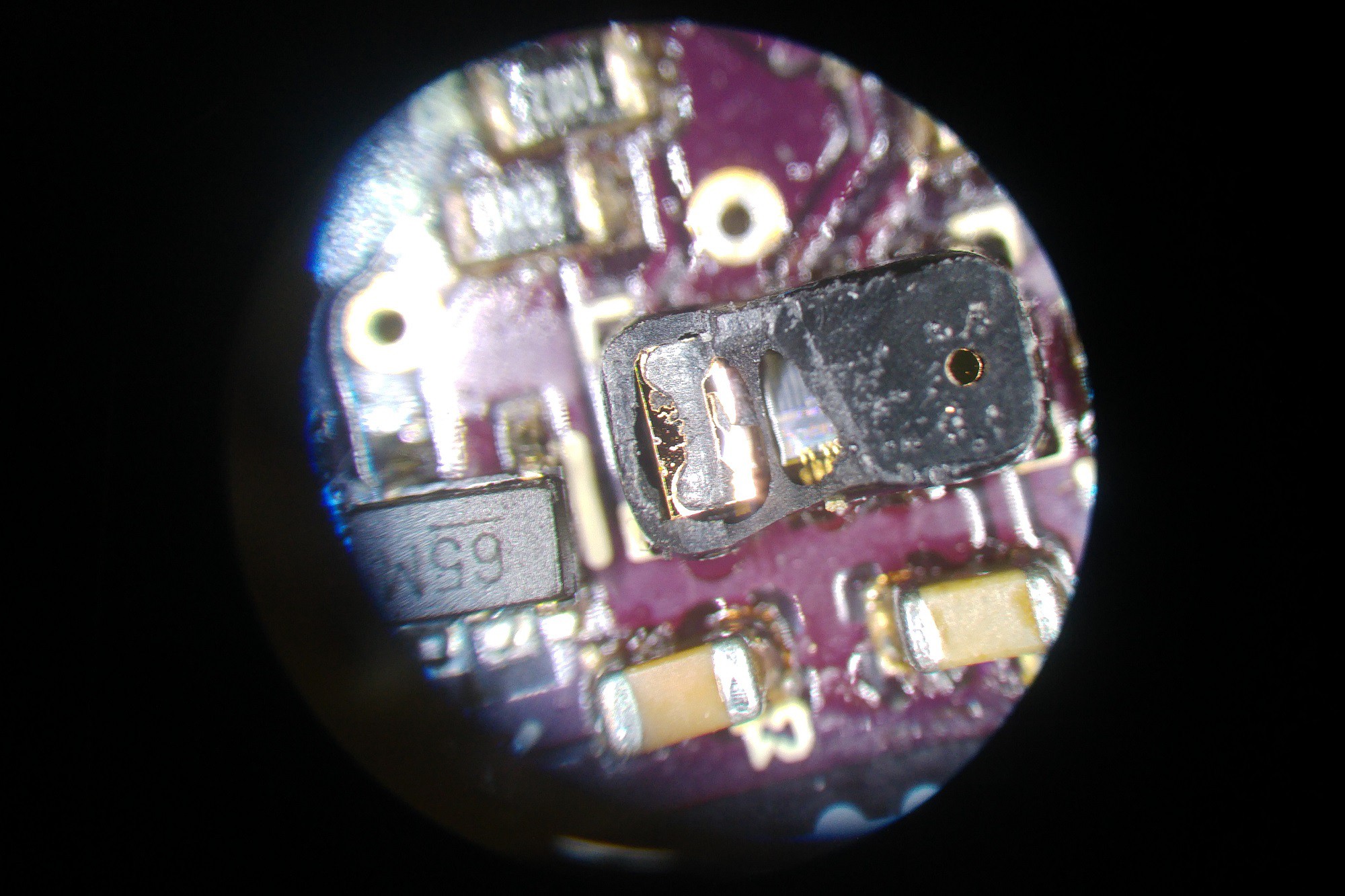
07/18/2017 at 08:58 • 8 commentsI killed one of my VL53L0X sensor modules, so instead of just throwing it away, let's do a teardown and take a look inside for your enjoyment.
Here's the chip with the start of the receiver side removed, you can see an IR filter in there on the left:
![]()
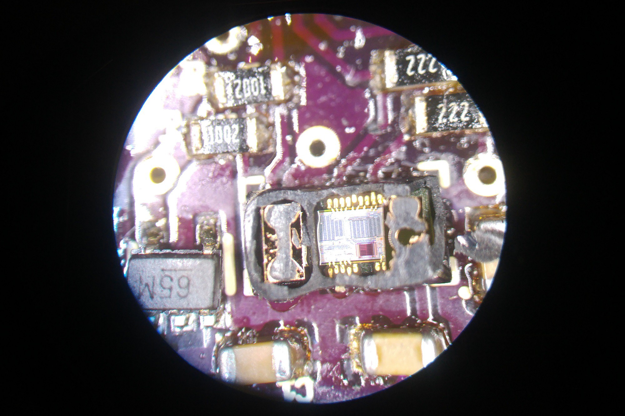
Taking more away you notice the left side is fully encapsulated to prevent light leakage from the transmitter (this is the collector side; left) and you start to see the die and the other IR filter on the transmitter side (right):
![]()
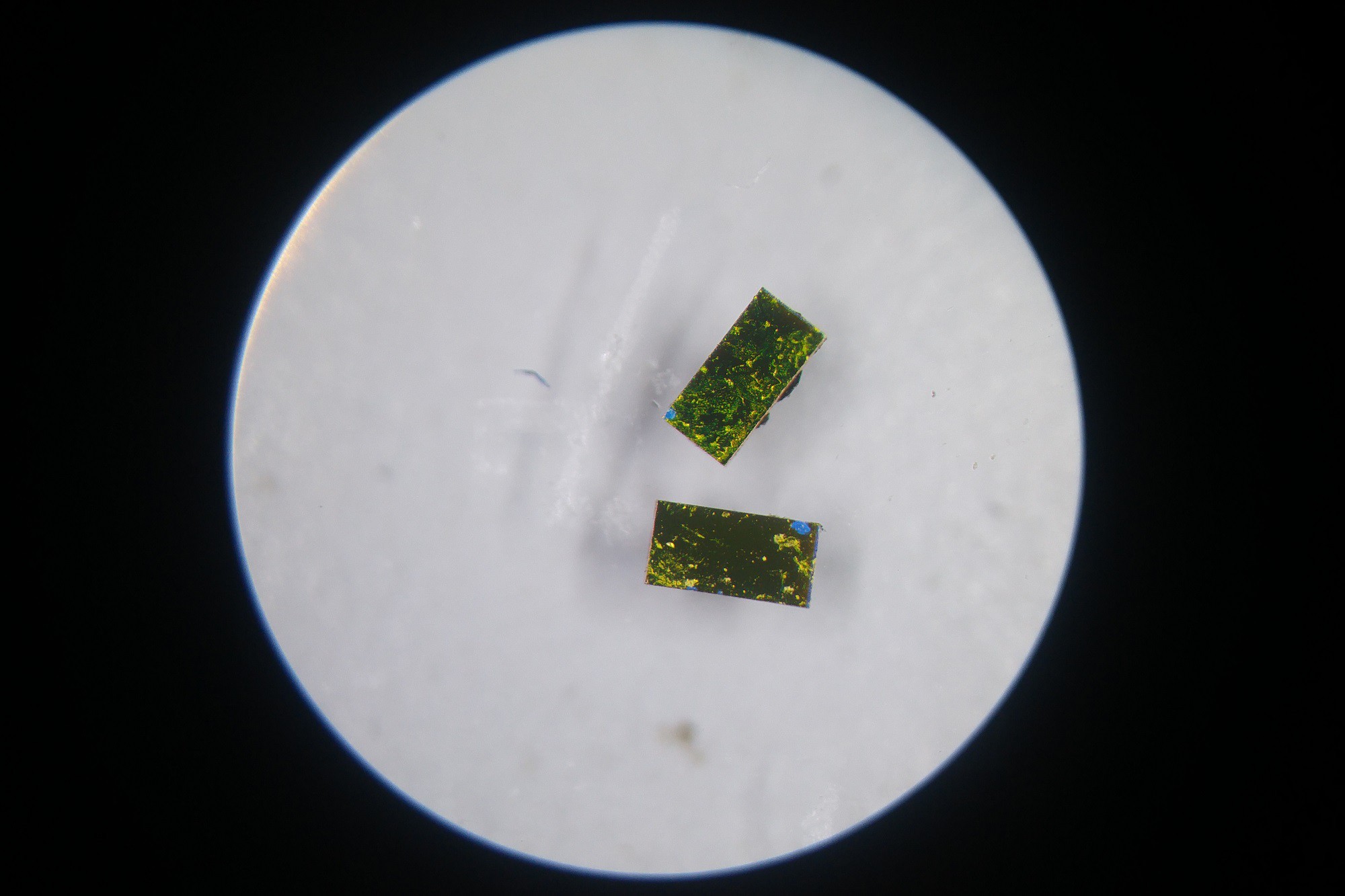
Here are the IR filters:
![]()
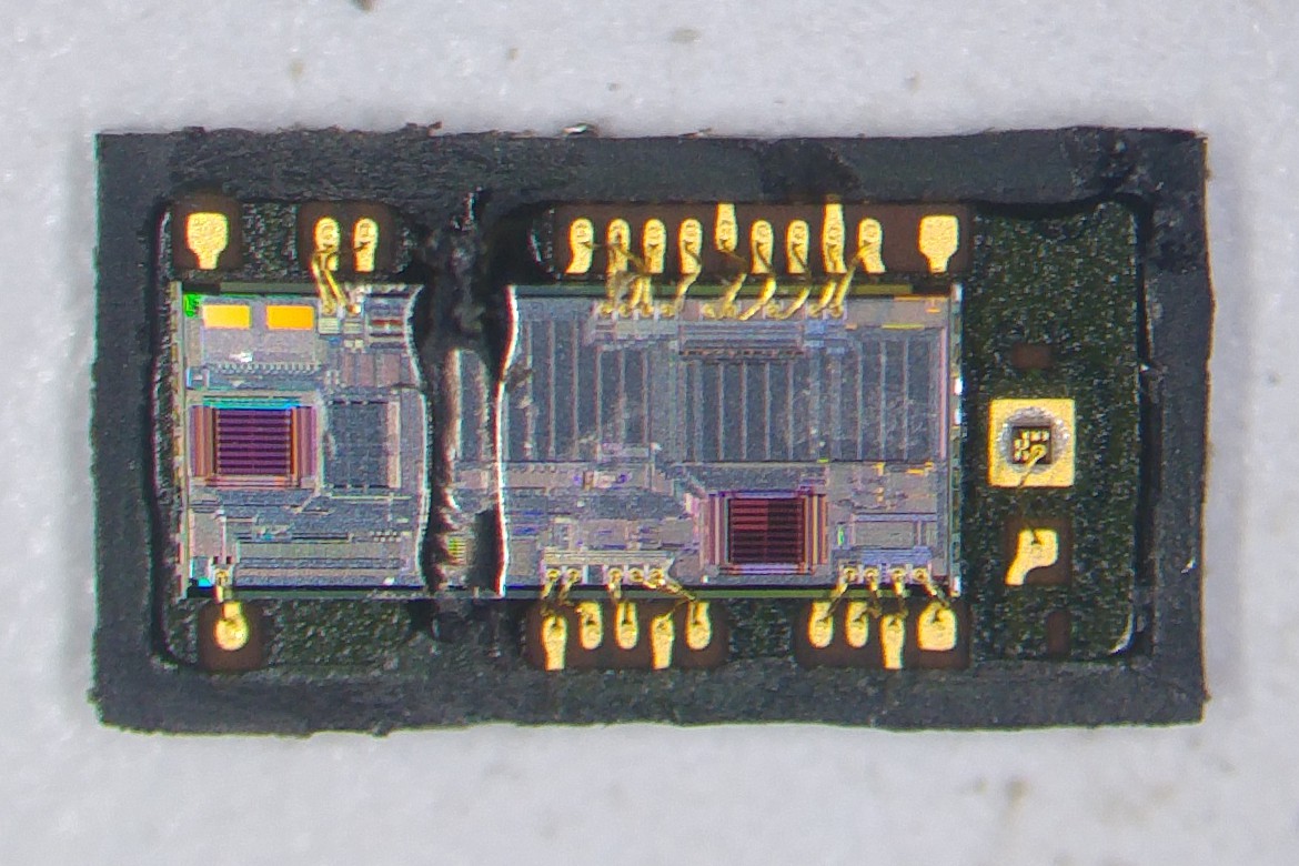
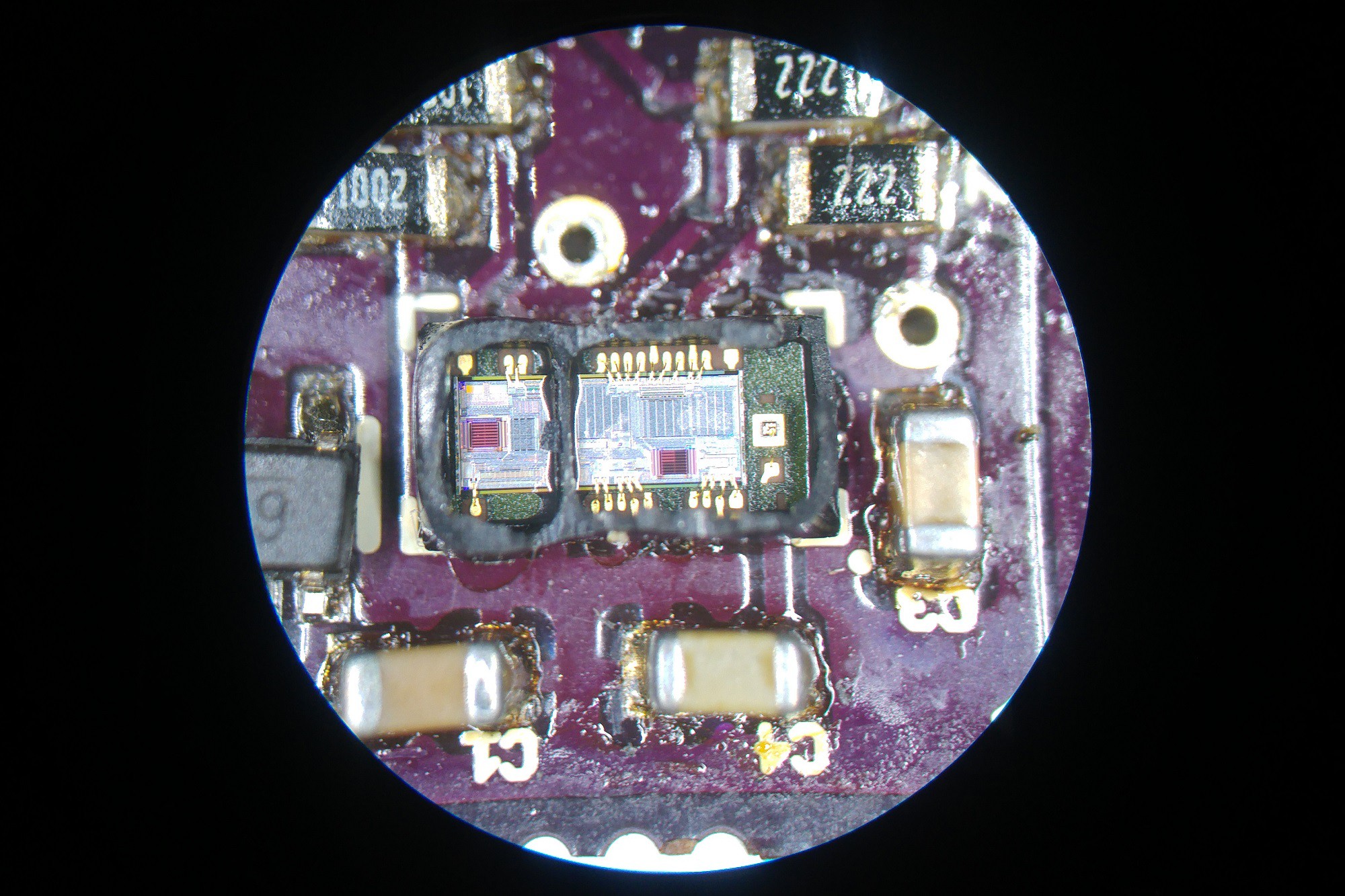
Removing both IR filters, you see the laser diode on the right and the rest of the die with the detection array on the left:
![]() And here's the chip removed from the board with all the casing removed:
And here's the chip removed from the board with all the casing removed:![]()
It looks like there is a secondary detection array near the diode for further timing analysis for ToF.
Very interesting little chip.![]()
-
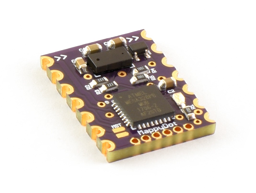
First MappyDot Working
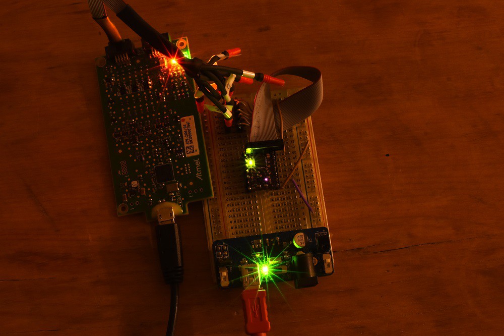
07/16/2017 at 08:12 • 0 commentsThe first MappyDot has been programmed and is operational:
![]()
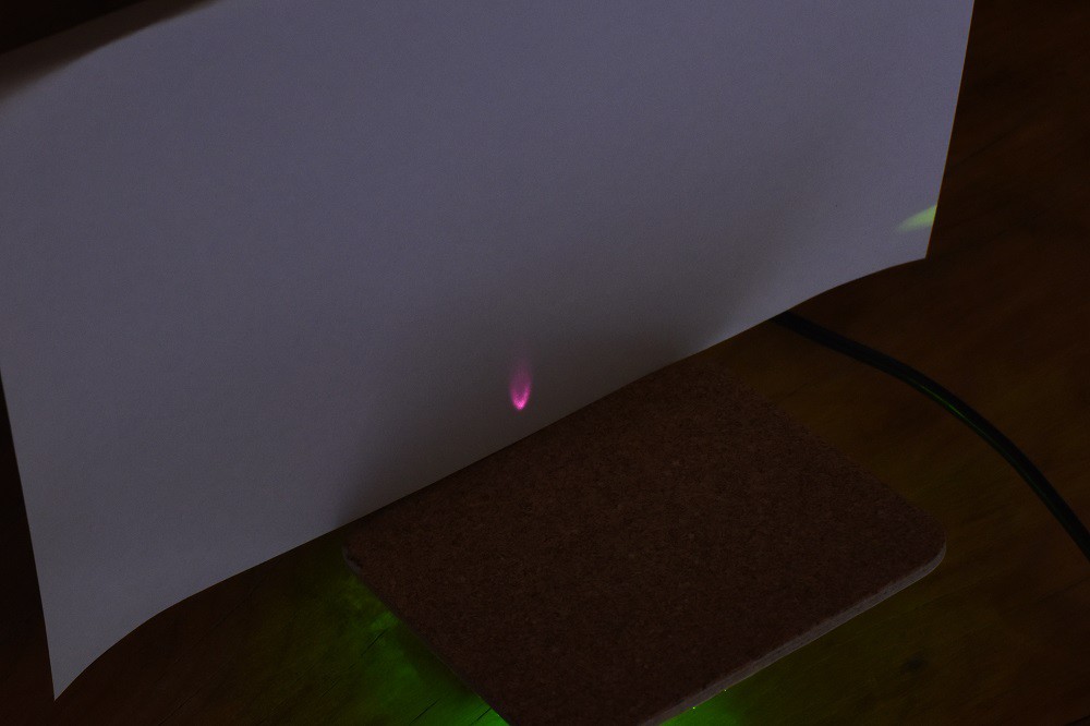
You can see the infrared beam coming from the VL53L0X sensor as it takes it measurements.
The following demo shows the LED lighting up after it reaches a threshold value (200mm):
And for fun:
![]()
-
Stencils!
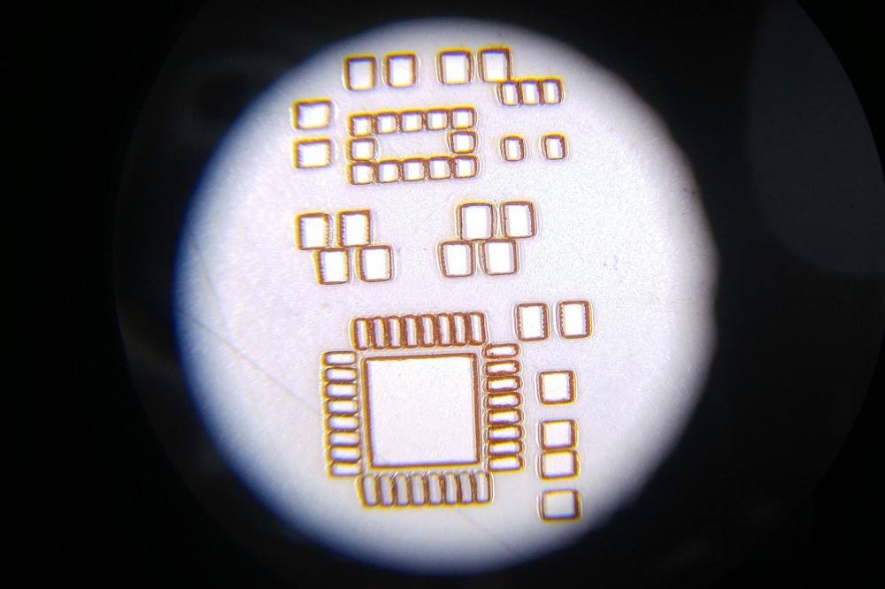
07/13/2017 at 11:35 • 0 commentsGot a few stencils etched up on some overhead transparency sheets:
![]()
There's still issues around the VQFN pads with these stencils, but should reduce the amount of solder paste on the board. Plus the VL53L0X pads are pretty decent, which are the harder ones to get right with a syringe as they are under the part itself.
![]()
I'll have some more boards made up this weekend with these stencils.
Edit:
After changing the pad layout a bit by reducing the size of the VQFN pads by 80% and reducing the speed and power:
![]()
Much better.


 To help with this, each MappyDot will by default actually do some of this filtering for you which reduces the processing overhead required to filter data from numerous sensors at once for general and rapid motion cases. You can turn this filtering off on the MappyDot if you want higher frequency motion data.
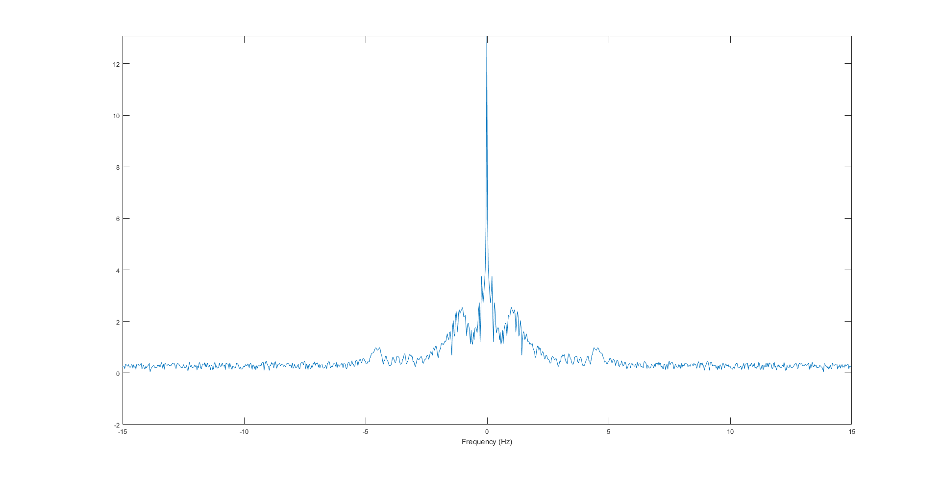

 4Hz cutoff (similar to 3Hz):
 If you compare that to the original data above, you will see that you get a pretty good representation of the data without too much information loss. Going much higher than 6Hz causes the data to start to fit to the higher frequency "spikes".
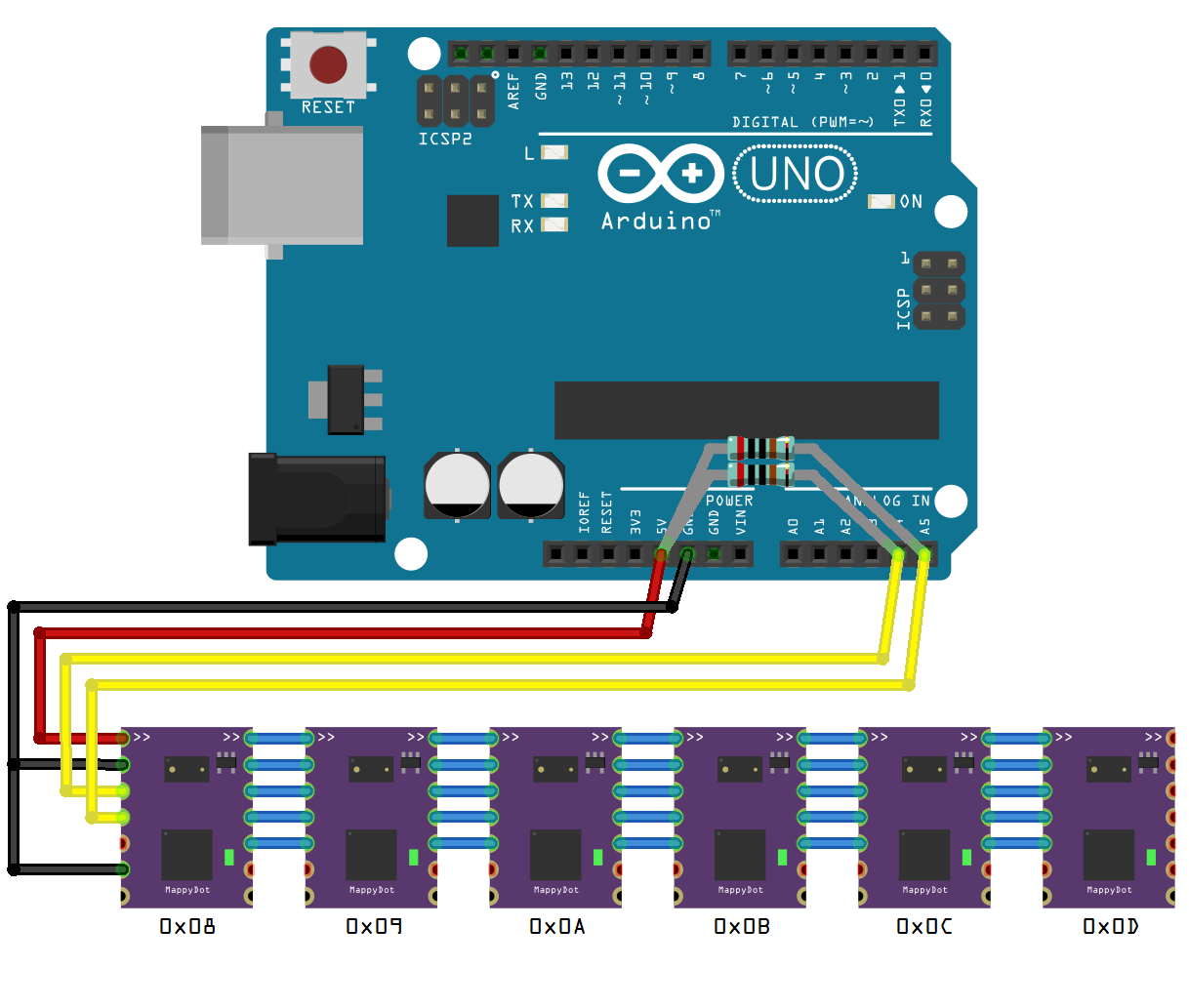 When the MappyDot switches on, all devices go into a discovery state and wait until they receive an address command. All except for the first in the chain which is the master. The master will first assign it's own address as 0x08 and then initialise the address protocol:
 And here's the chip removed from the board with all the casing removed: