Kumar, Abhishek
-
Documentation, Binaries download and instructional videos
10/21/2017 at 13:36 • 0 commentsIf you have received a BeagleLogic Standalone, please refer to this setup document which is a step-by-step guide on how to boot the board and capture logic data from it.
To download the PulseView binaries built with BeagleLogic Standalone support for Linux and Windows, go here.
The documentation for BeagleLogic standalone can be accessed at https://standalone.beaglelogic.net.
Documentation for BeagleLogic is available at https://docs.beaglelogic.net
I also created a set of instructional videos on how to use PulseView with BeagleLogic standalone. Here's the playlist (highly recommended you watch it in full, it's just 5 minutes for 4 videos):
-
.... And off to Hackaday for judging!
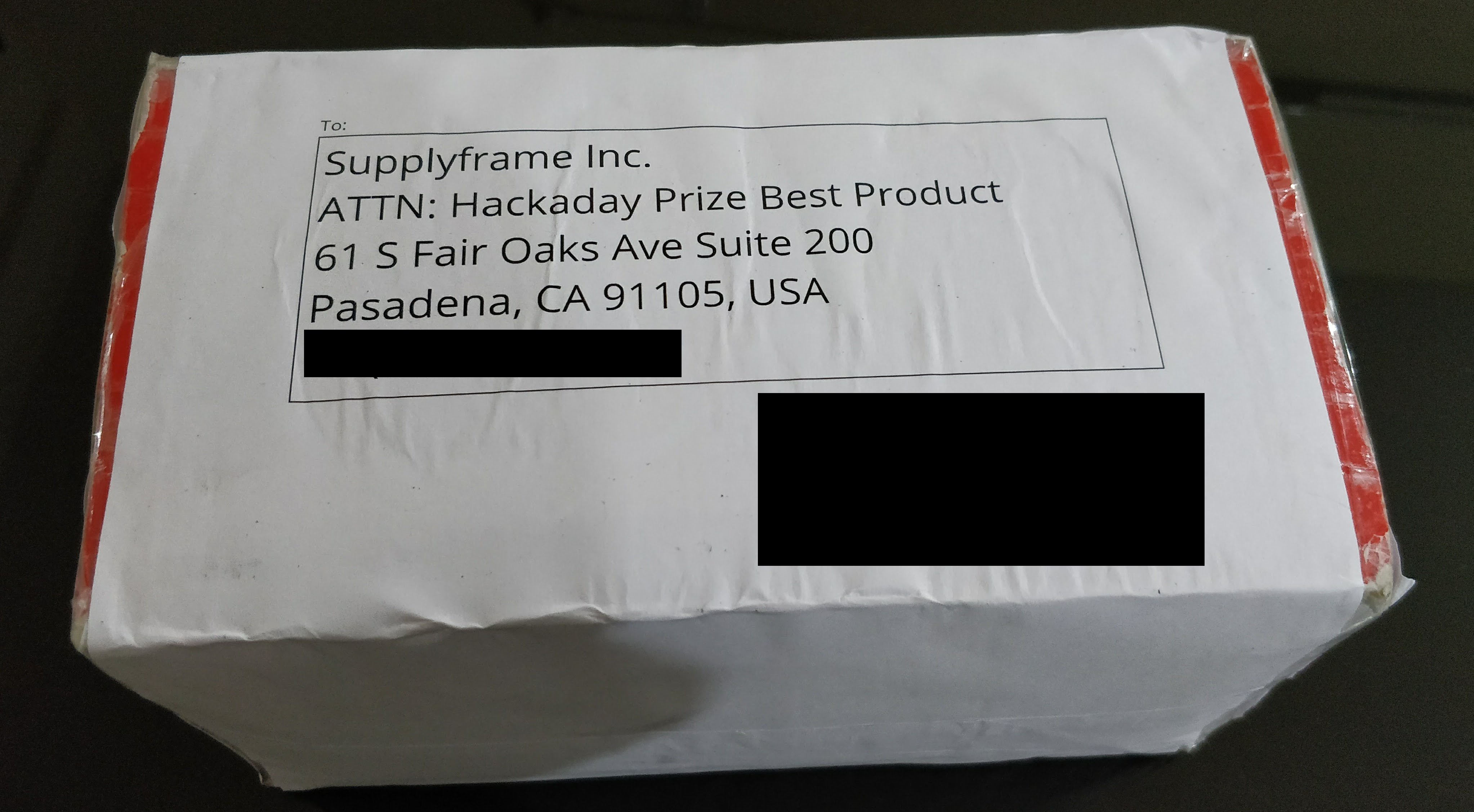
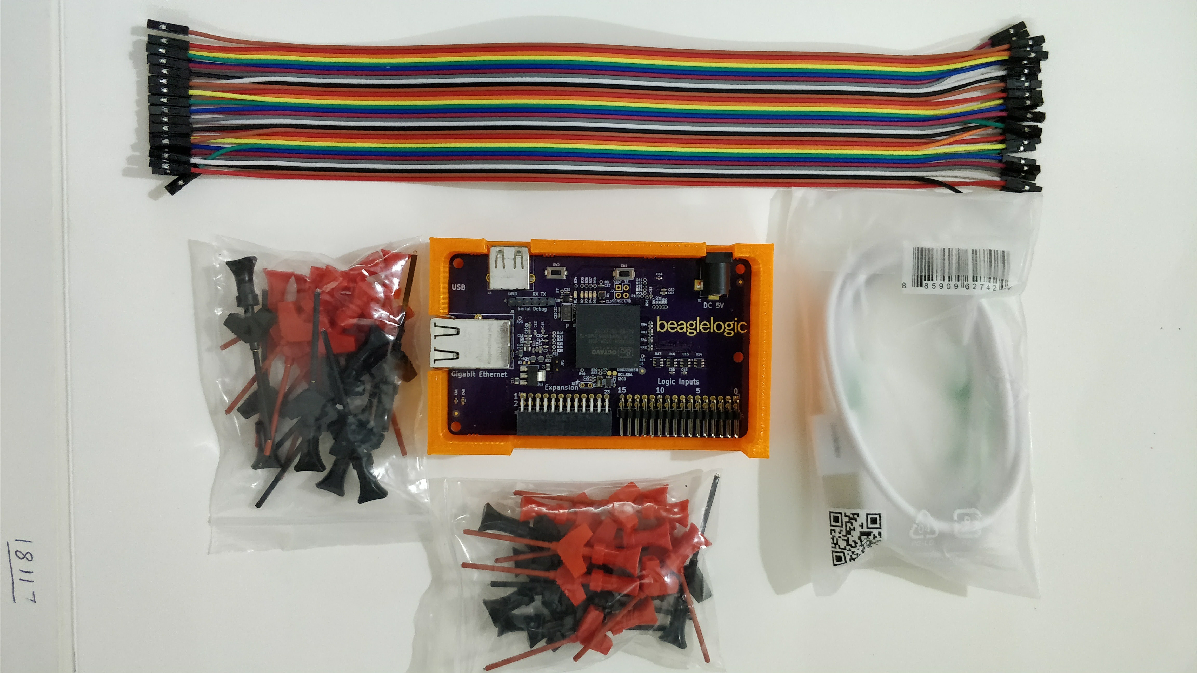
10/15/2017 at 16:41 • 1 commentLast Friday (13th Oct) I despatched the 3 BeagleLogic test units, along with a set of instructions for each, for judging. Here's a last view of the package contents before it was sent off:
![]()
And the package itself:
![]()
DHL says the packages will be in by Monday, the 16th. Let's see if they make it on time!
I'd like to thank OSHPark for the timely PCBs and GHI Electronics for producing the first prototypes! Couldn't have done it without your support.
-
Boxing
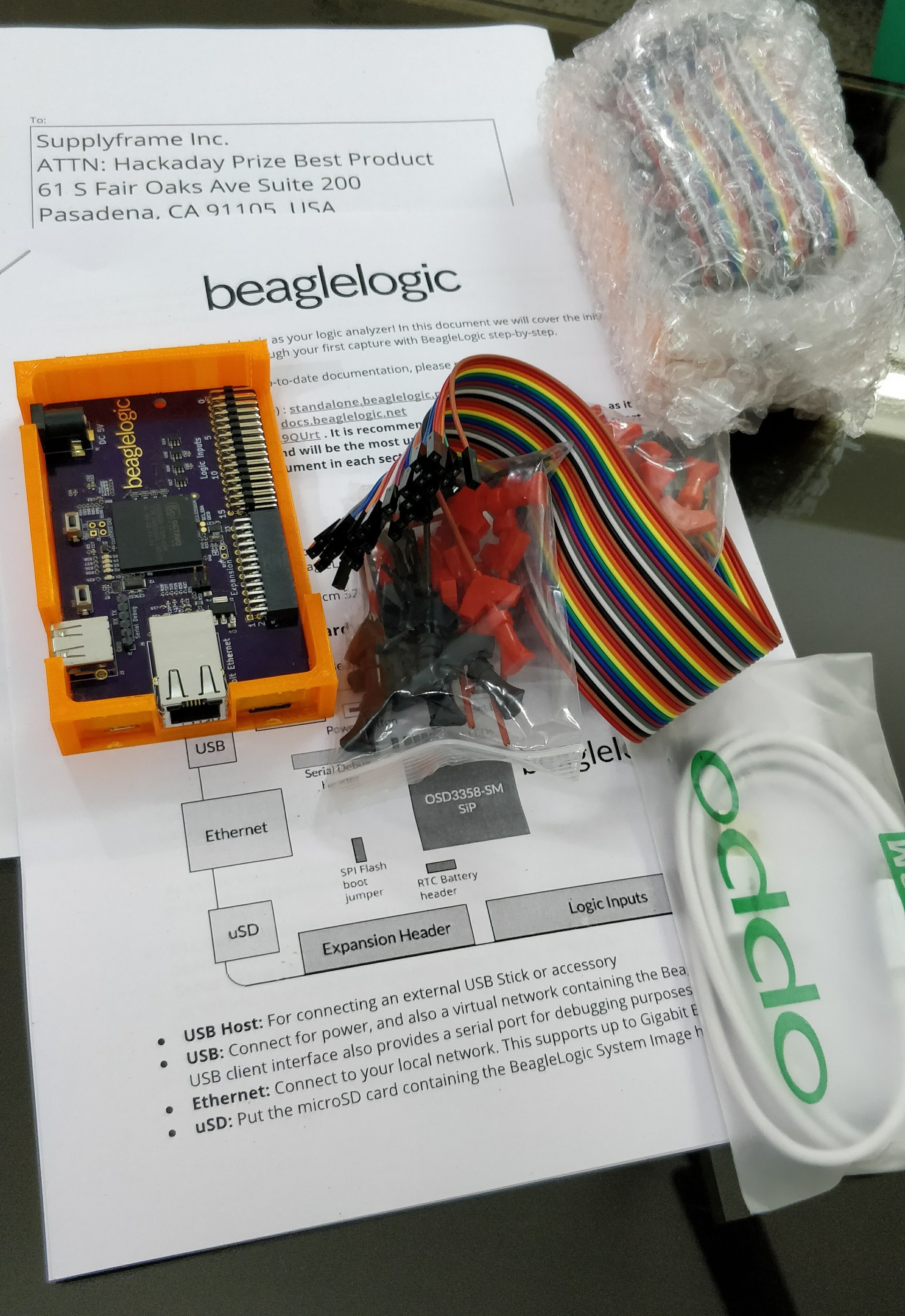
10/15/2017 at 16:34 • 0 commentsFor packaging the BeagleLogic standalone, I wanted to give the user a complete experience right from the unboxing to the first use. Hence I included everything a user might need to start using BeagleLogic. This includes a set of wires and probe clips, and a micro USB cable. The BeagleLogic standalone board itself is enclosed in a 3D printed case and already includes a microSD card inserted with the latest microSD image ready to boot.
![]()
3 such sets were prepared to be despatched for judging,
-
3D Printed Case
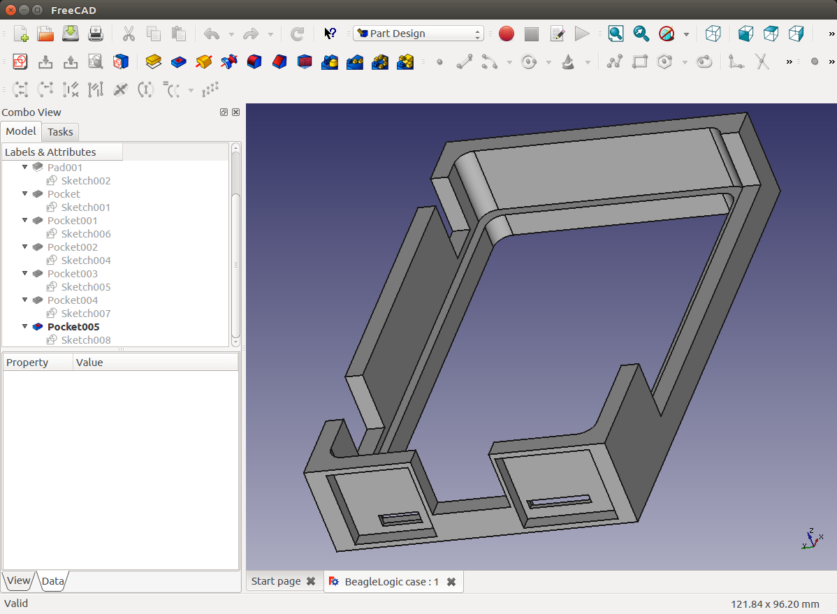
10/14/2017 at 18:55 • 0 commentsNow that the core functionality of BeagleLogic Standalone was working alright, I wanted to have it in a case for aesthetical reasons. However I wanted the case to be open so that the buttons and LEDs are user accessible. Also I wanted the golden BeagleLogic logo to show :)
I prototyped the case in FreeCAD. After a couple of false starts, I got a good design in the 2nd iteration:
The board is supposed to be a snug fit all the way into the case, no fasteners or screws needed.
The first and the second iteration were 3D printed in PLA - the first revision used blue whereas the second revision used orange. This is iteration 1. The problems of this iteration were that there was not enough margin on the edges to compensate for variation in the board dimension, so the board would be too tight to fit in completely, and that the connector positions were slightly astray. Also the edges were too thick and without a recession, the connectors won't fit. These were fixed in rev 2, as you can see above.
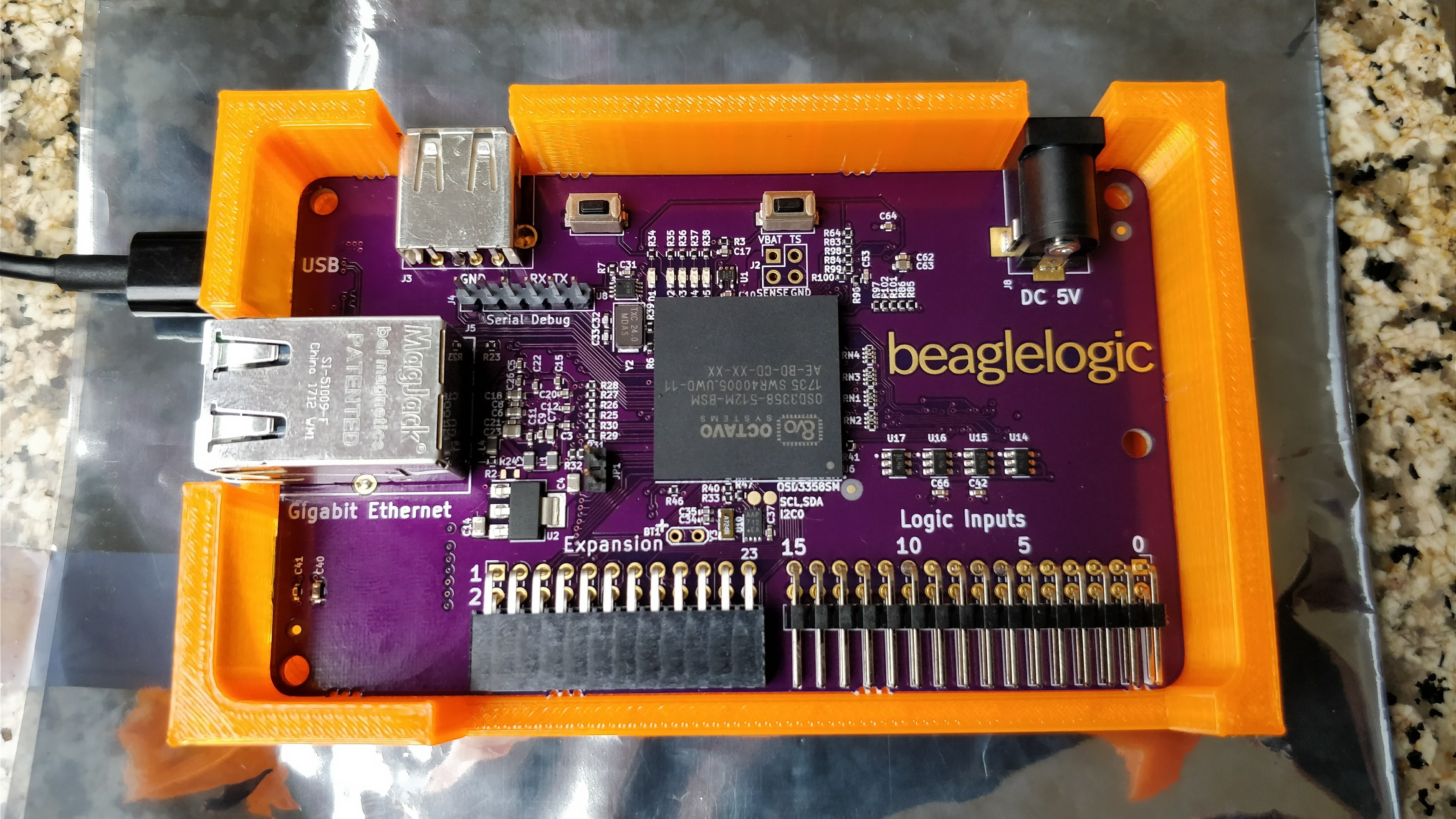
This is iteration 2, with the BeagleLogic standalone board comfortably seated.
![]()
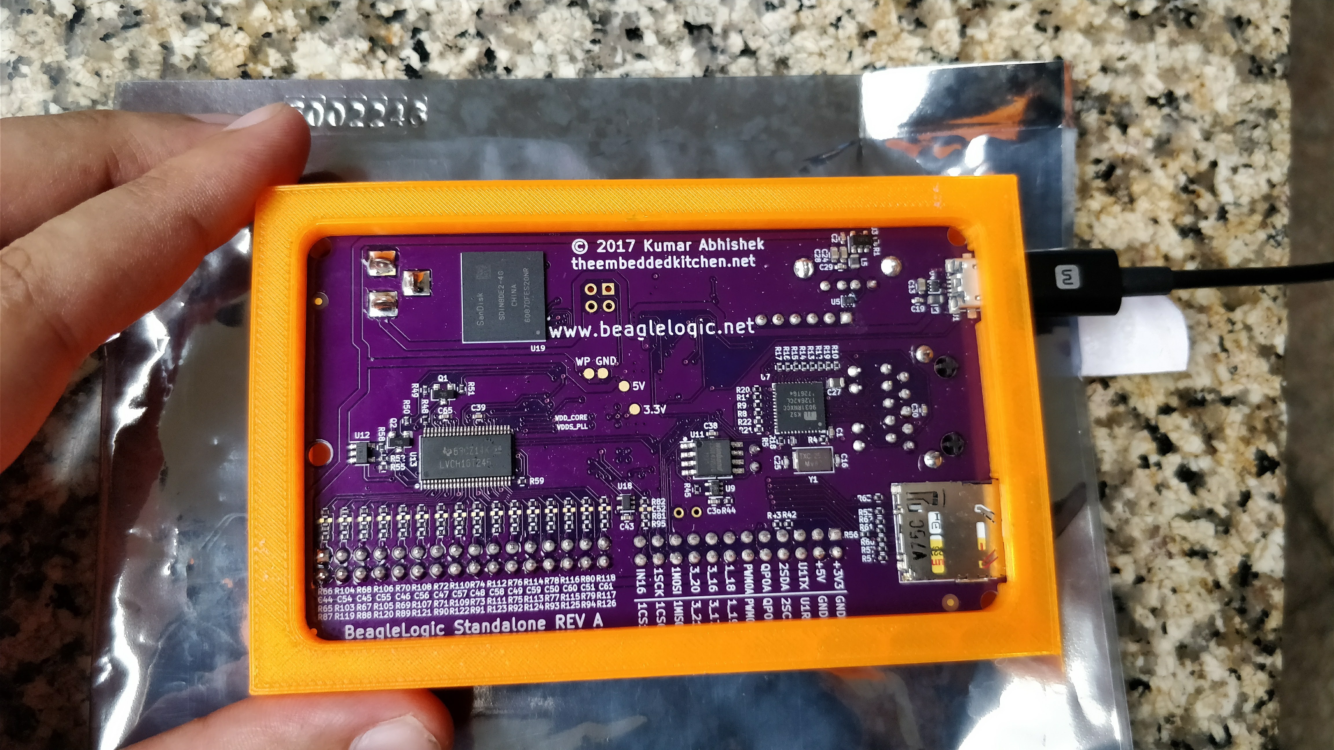
From the back:
![]()
I printed a few more copies of the case, and it was all set.
-
BeagleLogic server goes Go
10/14/2017 at 16:14 • 0 commentsI posted about how BeagleLogic could now be used via the TCP backend. It involved writing a TCP server in NodeJS that ran on the BeagleBoard hardware (BeagleLogic standalone / BeagleBone(s)) .
However I soon realized that the NodeJS was a memory hog. After doing two large captures (100Msamples) with the BeagleLogic, I was left with < 50MB of free memory on the board! A few more captures and I was certain the board would have crashed. This wasn't going to be good.
I saw on my Twitter feed that someone had tweeted that "writing servers in Go is a pleasure". Well I had to write a server and fast. So I decided to write a prototype in Go and it was rolling in a few hours. I started in the afternoon, and by the evening I had data streaming out of BeagleLogic in Go. The memory footprint? A few MB, which was a significant improvement compared to the NodeJS counterpart. The best part? There's no difference to the end user, it's totally invisible.
Here's the code on GitHub in case you are interested to take a look.
Will I write more code in Go? I found the language interesting, even though I was writing this on a very tight schedule and had just a few moments to learn the language. I might write more code in Go, but I guess this would be all for now.
-
Bringing up the peripherals and the logic analyzer section
10/14/2017 at 15:06 • 0 commentsWhen I first booted the board, I booted it using the device tree sources for the PocketBeagle as a fail-safe as the board was not really booting until the second patch was applied to u-boot (see the previous log). Once I had the board booting with the second patch applied to u-boot, I switched to my own version of the device tree sources which can be found here, and booted the board with it. It booted successfully.
Once the device tree was in place, the next step was to verify whether all peripherals were appropriately recognized and there. One by one, I got the eMMC, USB Host, Gigabit Ethernet all working. The SPI Flash and RTC are the only peripherals that are currently untested and this is due to them being lower on the priority order right now.
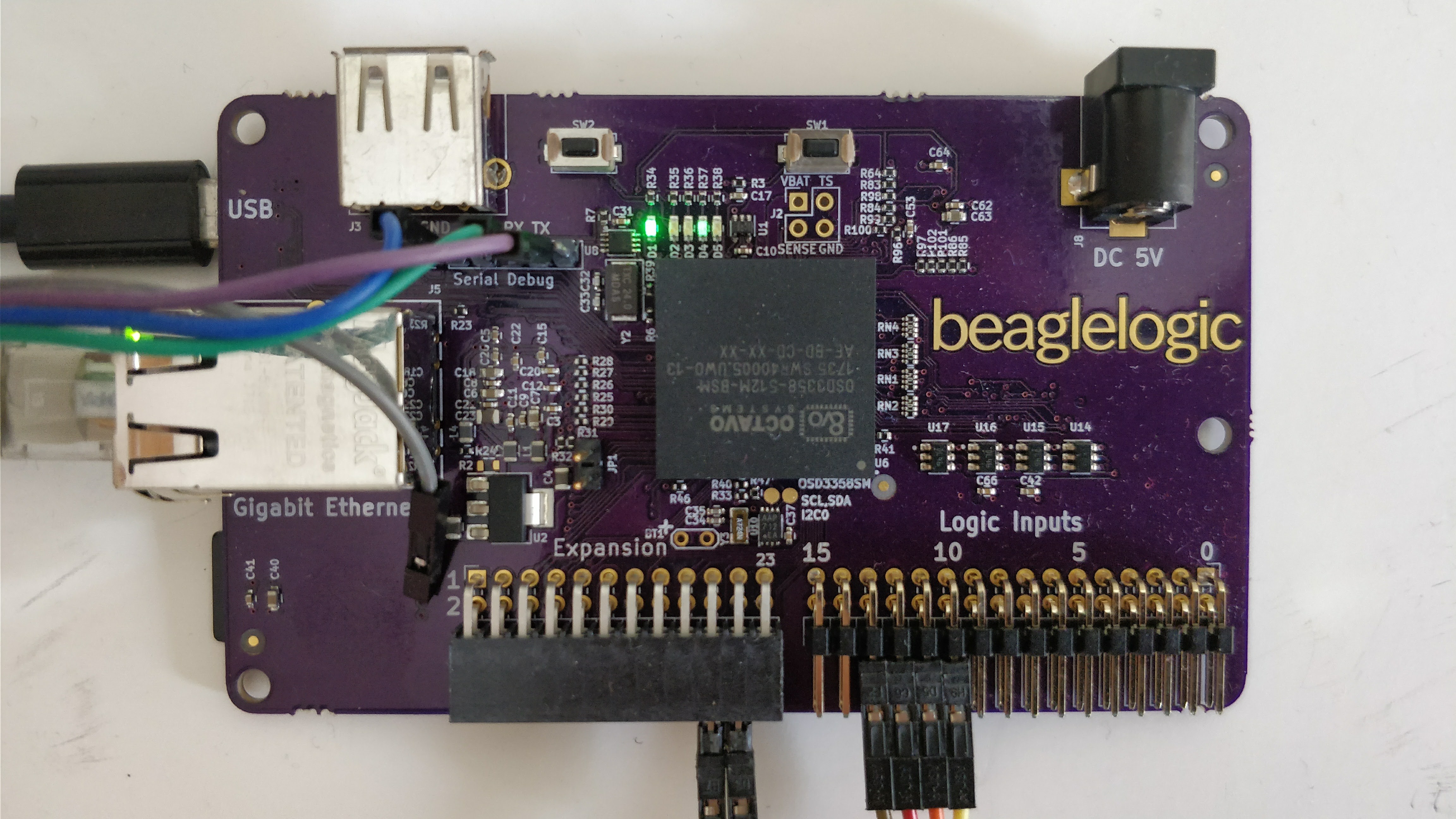
Then the next step was to get BeagleLogic installed on this thing. I installed it, and it was successfully detected. And the moment of truth was to get some logic samples captured. Before I could do that I had to make some changes in the startup script of BeagleLogic so that the GPIOs that enable the 74LVCH16T245 logic buffer on the chip were set correctly.
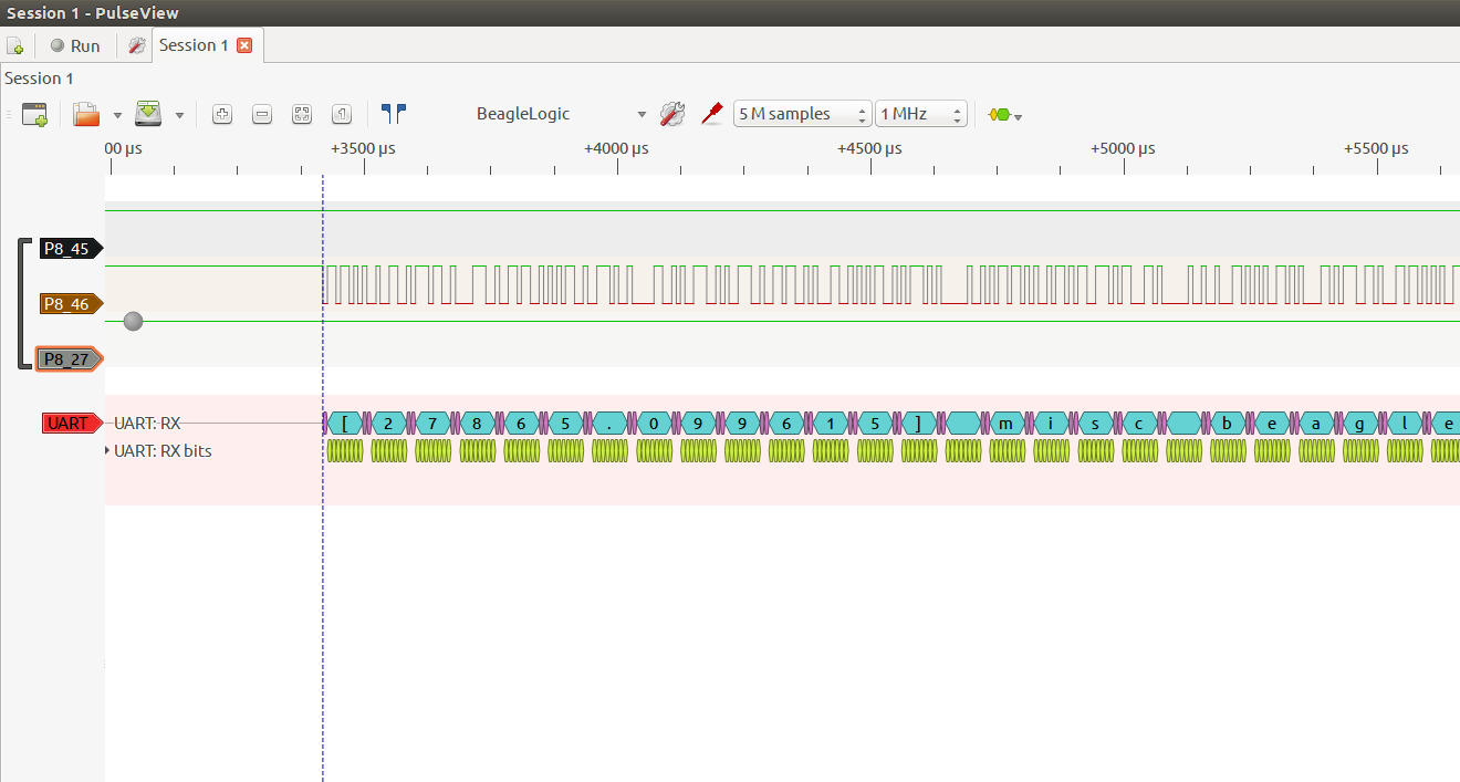
After that, here are the results using PulseView:
![]()
The board captured its own UART serial console stream that was connected to the TX Pin on the 6-pin serial console header.
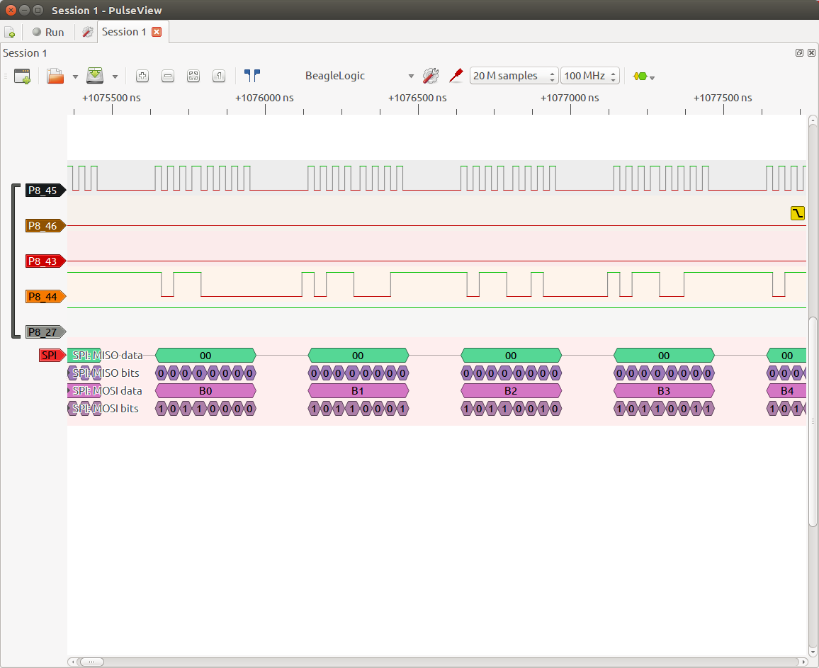
One more example I made was the board capturing an SPI stream at 24MHz which is the fastest signal the BeagleLogic standalone board can capture, at 100MSa/s (according to Nyquist, it's Fs/2 = 50MHz but because the rising and falling edges need to be captured, it becomes Fs/4). Here are the results:
![]()
All in all, this means that the board bring up was successful! No blue wiring needed. The logic inputs also happily took 5V without affecting the performance, so this was great too.
-
It boots!
10/14/2017 at 13:39 • 0 commentsAfter I got the boards on the 4th of October, I set about getting them to boot. Robert Nelson provided the first set of patches into u-boot adding support for the BeagleLogic board (thanks Robert!). Even after the patches, the BeagleBoard u-boot bootloader expects a board ID in the on-board EEPROM of the SiP in order to recognize the board and boot it correctly. To program the EEPROM, the board needed to be booted. How to solve this chicken-and-egg situation?
There are two ways - (i) Write the EEPROM using u-boot and (ii) Apply a third patch to u-boot that causes the board to be recognized as a BeagleBone (the original, white one) and once booted, write the EEPROM from userspace. I chose the second option.
I got stuck after writing to the board EEPROM, the board refused to boot once the EEPROM was written to. I dug deeper and found that it was a voltage scaling issue, the voltages to the CPU were not getting set correctly causing the board to crash once control was handed over to the kernel from the bootloader. This led to a second set of patches that went into u-boot. That led to this:
![]()
Yes, the board booted. However the peripherals needed to be brought up. That will form the next project log.
-
Assembly
10/10/2017 at 04:15 • 2 commentsOnce the boards were ready from OSHPark, they were sent over to GHI Electronics for assembly on the 26th of September. GHI Electronics is also the manufacturer of the new PocketBeagle boards that uses the same OSD3358-SM SiP as BeagleLogic standalone does. Had it not been for them, I probably wouldn't have been able to get the boards back in time for the Best Product round.
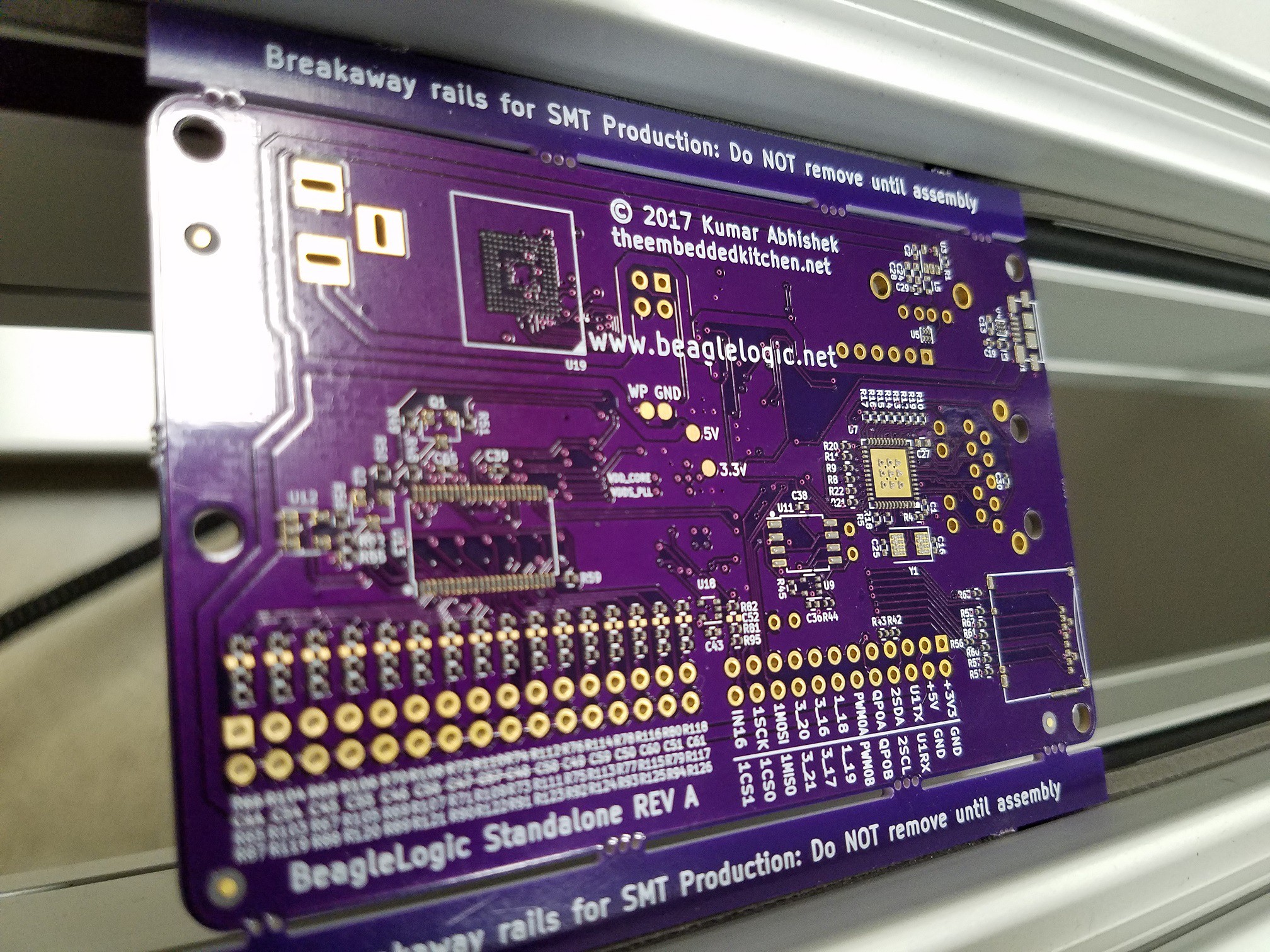
They were kind enough to send a few pictures and videos of the boards undergoing the assembly process. Here are the pictures:
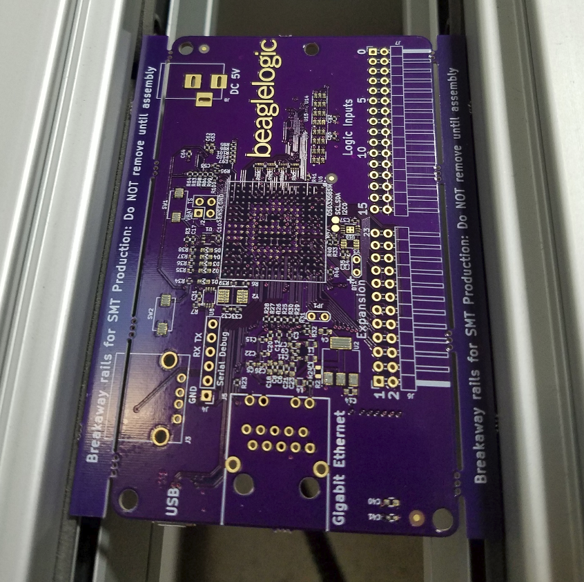
1. Bottom side, after solder paste application.
![]()
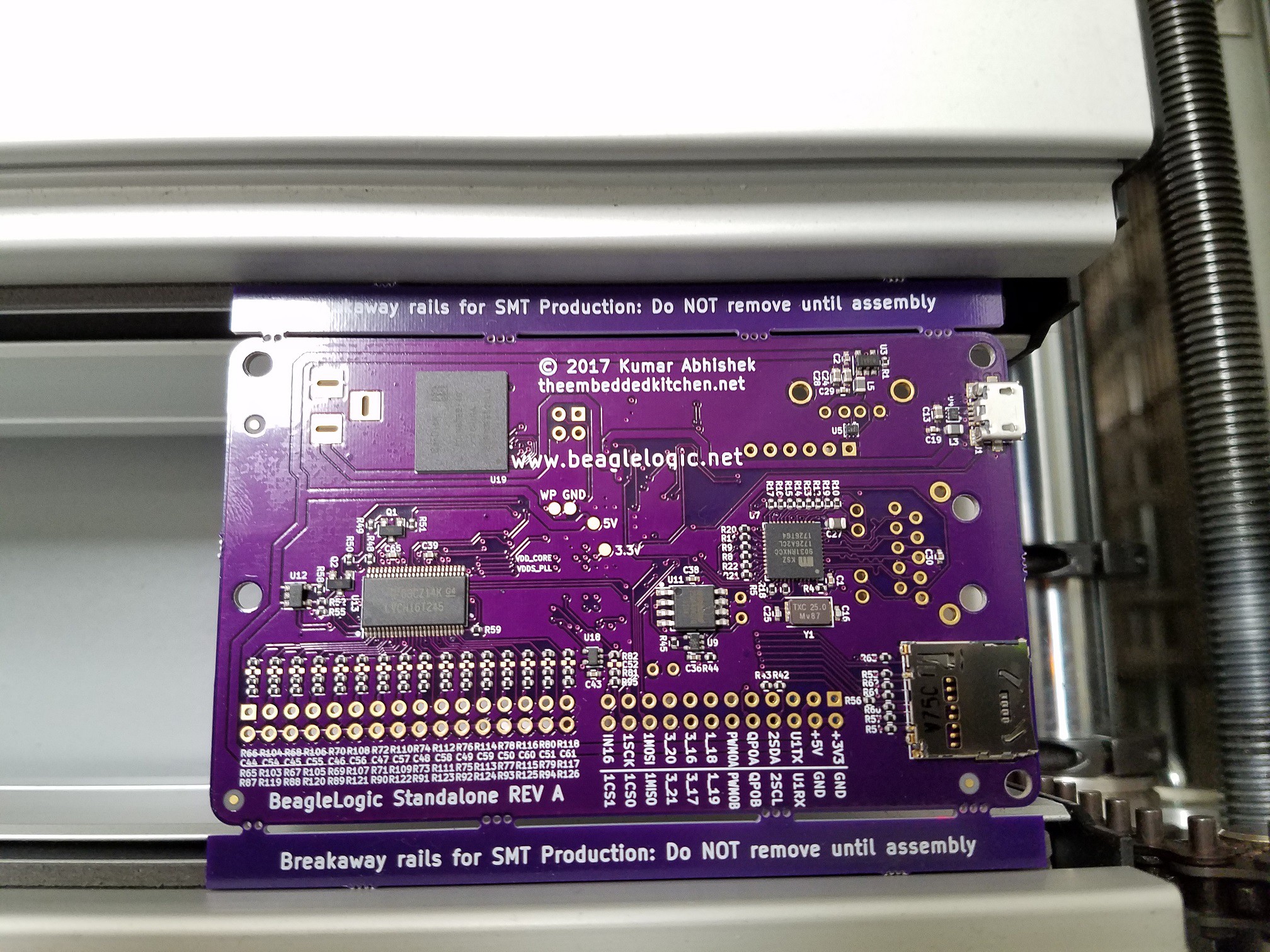
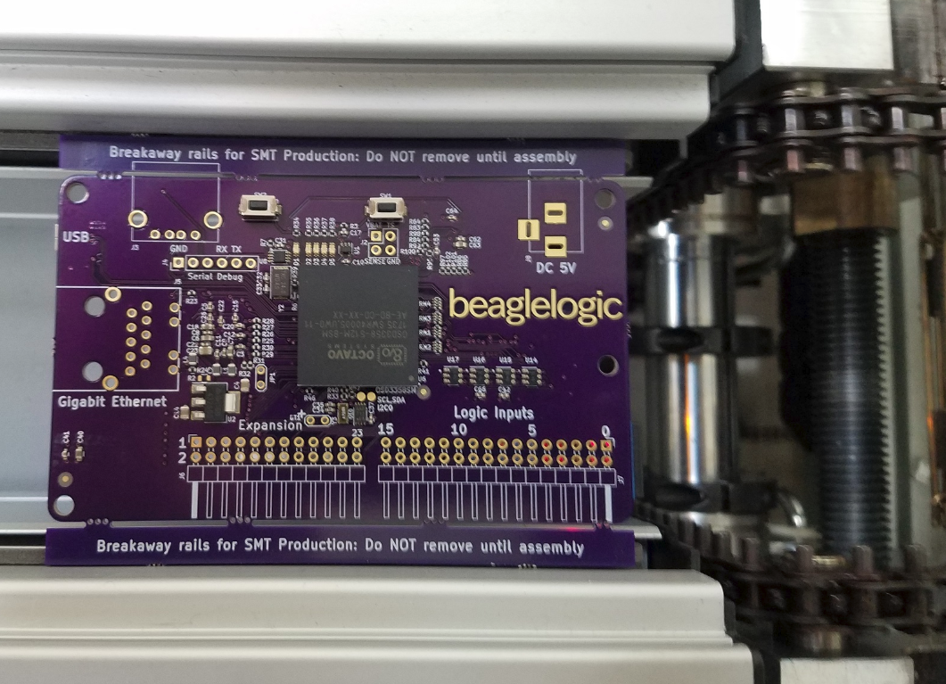
2. Bottom side, all parts placed
![]()
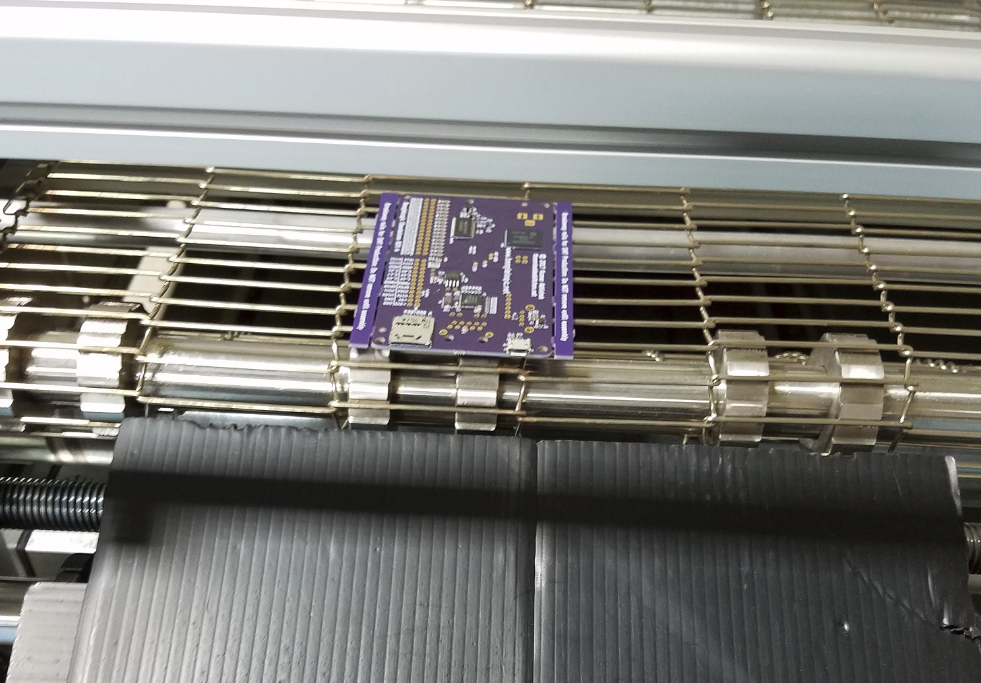
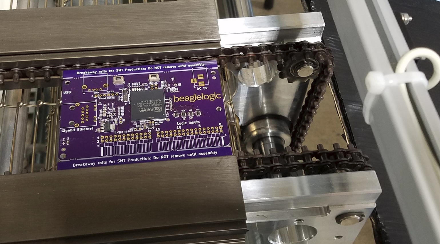
3. Bottom side, coming out of reflow
4. Top side, after application of solder paste
5. Top side, after Pick-n-Place
6. Top side coming out of reflow:
The boards were shipped to me on the 28th September, and I received them on the 4th of October. The wait was excruciatingly long, and I was brimming with excitement when I received them. More on the board bring-up in the next post!
-
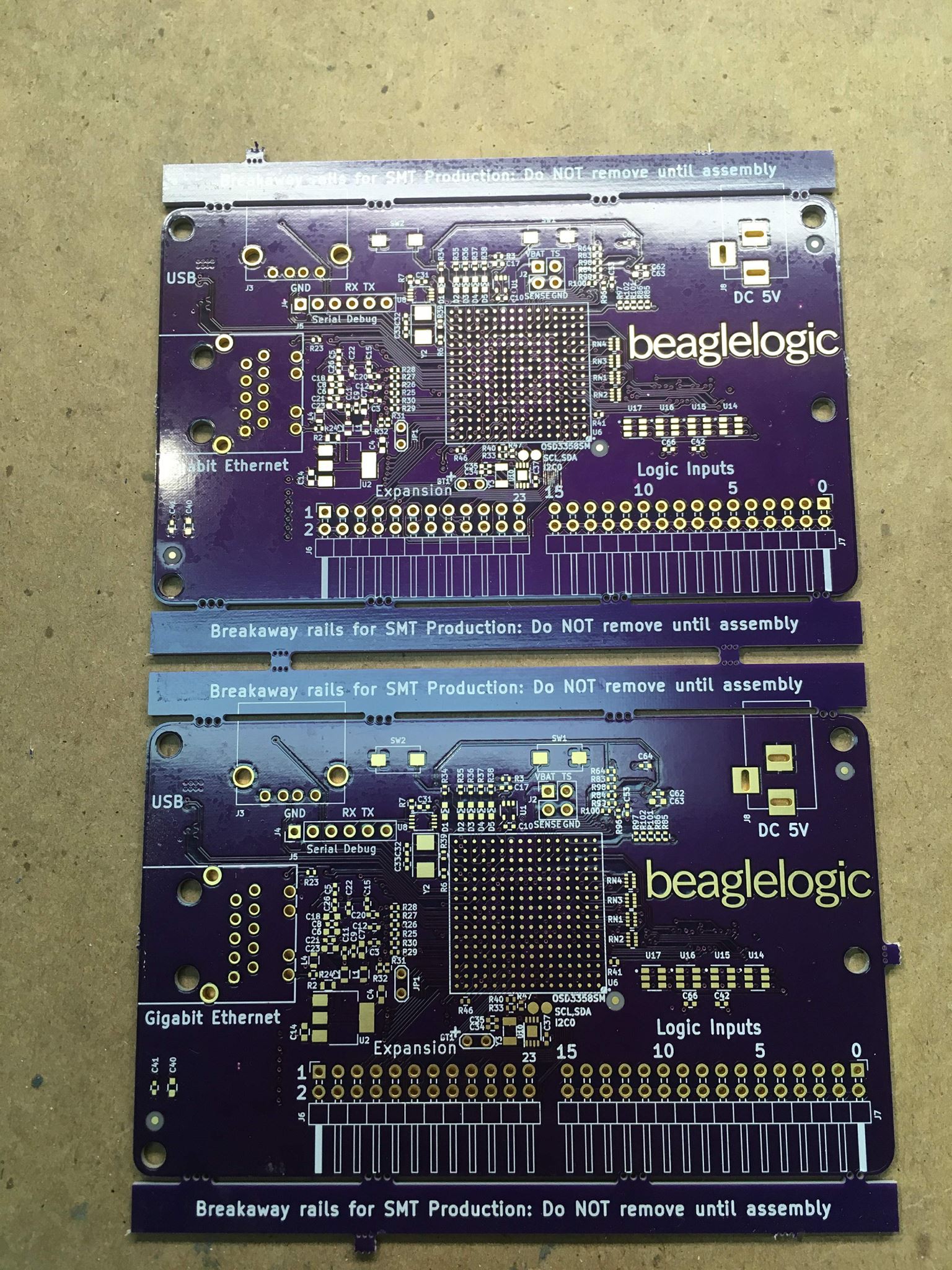
Boards Arrived at OSHPark!
09/27/2017 at 04:03 • 1 commentHere's a pic of the fabricated boards sent from OSHPark, before they got shipped off to GHI Electronics (thanks Drew!):
![]()
I'm excited to see how these turn out after assembly.
-
Major change in how BeagleLogic can be used
09/23/2017 at 16:52 • 0 commentsPreviously, in order to use the data generated from BeagleLogic and further analyze it, one had to:
- SSH into the BeagleBone
- Execute sigrok-cli to capture data
- Get the data out of the BeagleBone using SCP/SFTP/FTP
- View the data/further process it using PulseView , the official GUI client for sigrok.
Complicated, right? Not anymore.
With the new BeagleLogic TCP Server and TCP client for BeagleLogic in sigrok, one can now directly visualize the data in PulseView on the PC itself by connecting to a local or remote BeagleLogic. All you need is the IP address of the BeagleLogic, and you're set.
Here's a video of the thing in action:
How this works is that there is a TCP server runs on the BeagleLogic (written in Node.JS, code can be viewed here) and serves data to sigrok running on the PulseView GUI that acts as a desktop client. I've written a TCP backend for the BeagleLogic driver in sigrok that connects to the BeagleLogic server and retrieves logic data.
And now, regarding the BeagleLogic standalone build, all the components have arrived, just waiting for the PCBs to arrive before assembly commences. GHI Electronics, LLC will be building the first prototype units of BeagleLogic, and I can't wait in excitement to have the first units of BeagleLogic Standalone in my hands by the end of next week!
BeagleLogic Standalone
BeagleLogic, now as a turnkey and standalone 16-channel Logic Analyzer