-
2017-07-22 (Sa) Pi0 Laser Tag PiTagErrUs
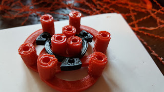
08/17/2017 at 16:50 • 0 commentsParts for the front of the tagger were printed. Some of the dimensions were not printed precisely enough on a 2+ year old printed. To make sure all the holes were the correct dimensions, drill bits were used to plunge through each hole. This ensured each hole would be the correct size all the way through.
Printed parts being drilled
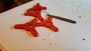
The emitter holders were a different story. They were tapped using an ordinary tap, usually used on metals like mild steel and aluminum (aluminium) but they had no trouble tapping plastic. If these pieces are not tapped, it is necessary to use a nut on them which is a perfectly reasonable solution. If only a few taggers are being built, a tap would be an unwise investment since nuts are so inexpensive.
Tapped Emitter Holders
The drill bit sizes were documented on a tracing of the forward array for reference while the rest of the arrays were drilled. The small 5/32" (4mm) holes were for long machine screws 2 1/2" (65mm). The 1/4" (6.5mm) holes were for the LED holders and the 1/2" (12.5mm) holes were for the laser emitters.
Hole sizes for Forward Array -
2017-07-19 (W) Pi0 Laser Tag PiTagErrUs
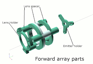
07/20/2017 at 12:02 • 0 commentsAll the names being tossed around for the parts of the tagger were finally committed to an image which explicitly named each piece. This was important for the instructions so anyone following them knows which part is being referred.
Labeled tagger partsA similar diagram was made for the lens focusing parts inside the forward array. These parts were too small to name on the large diagram and they were hidden inside the other parts.
-
2017-07-17 (M) Pi0 Laser Tag PiTagErrUs
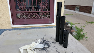
07/19/2017 at 19:28 • 0 commentsThree pipes were cut to different lengths at the hack space. The shortest length had been cut a long time ago but it may make a suitable pistol-style tagger. The middle length was cut to the prescribed lenth of the previously assembled tagger. The longest length was simply a matter of leaving one pipe extra long because cutting away the top would have created a wasteful piece.
Masking tape was applied to each side and the center lines were drawn. All the holes were marked at the same time and pilot holes were drilled at the same time. The large holes were drilled with a step drill bit. Marking and drilling multiple taggers only took a few additional minutes compared to the setup, execution and clean-up of a single tagger.
Cut and drilled pipes
Some of the holes were misplaced on the previous diagram. A new diagram was sketched and appears below. The old diagram put the PCB holder too close to the accessory rail riser. It should also be noted that drilling through masing tape can leave residue on the drill bit but the tape should be left on the bottom of the tagger so the handle and foregrip can be aligned properly. I failed to keep the tape on and it will make attaching these parts more difficult later.
Updated measurements for pipe -
2017-07-11 (Tu) Pi0 Laser Tag PiTagErrUs
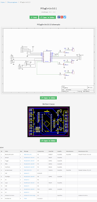
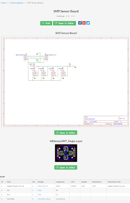
07/19/2017 at 19:27 • 0 commentsEverything was released for the printed circuit boards. Technically, everything was available for the PCBs but this post brings it all into a convenient-to-access location. On EasyEDA.com, it is possible to generate a public project page for each circuit board. From the project page, people can branch off to make their own modifications to the board, download their own set of Gerber files, or simply order copies of the boards. There is no fee for downloading
Screenshot of public project page for the controller board
Links for the Gerber files and project pages have been added to the Downloads section below. In order to get the project pages ready, some unnecessary files were deleted to avoid confusion. Two versions of the controller board were released but the homemade version should only be used if people wanted to make the board at home with basic supplies since it used thicker traces but the components were harder to insert and the silk screen may not be accurate.
Screenshot of public project page for the sensor board -
2017-07-10 (M) Pi0 Laser Tag PiTagErrUs
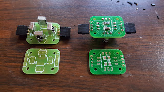
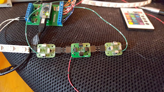
07/19/2017 at 19:24 • 0 commentsNew PCBs for the infrared sensors arrived as well as infrared sensors. These sensors were significantly less expensive but the quality may be less. Hopefully, using four together will make up for the difference in quality with a difference in quantity. Two of the boards were populated and their assembly was easier than the previous PCB revision but no less functional.
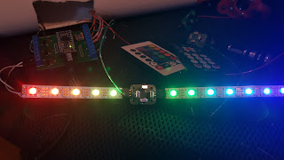
Two Rev2 boards populated and two bare PCBsOnce the boards were assembled, each board took less than ten minutes, they were plugged into the LED string for power and the signal wire was run to the controller PCB. Each board tested well and reliable data was received from an infrared remote which was sent over the USB.
Sensor board inline with LEDsAll the assembled boards were chained together, including the single sensor at the front of the tagger. Each signal wire was simply run to the same screw terminal. Somewhere it was suggested that an OR gate should be used to running these signal in parallel but this seemed unncessary.
Three chained sensor boards -
2017-07-09 (Su) Pi0 Laser Tag PiTagErrUs
07/19/2017 at 19:23 • 0 commentsScrew holes were countersunk so they would allow the screws to sit flush once installed. The screws were too long in many cases which lead to unwanted screw shafts inside the pipe. From the outside this was not noticeable.
Countersinking screw holes
Having the screws sit flush was worth the effort of countersinking the holes. In places like the trigger it was important to have the screws flush because a finger will be moving across that area all the time. In places like the yellow reload button, it will be possible to slap the button without smashing into raised screw heads.
Trigger assembly with countersunk screws
All the holes necessary for a complete were drilled. All the glue-ready pieces for a complete tagger were glued. All the screws necessary hold everything in place were installed. The electronics were still missing from this tagger but it was assembled and it could be handled.
This was the first hands-on test of the handle and foregrip which had been glued yesterday. They felt sturdy and reliable. Attaching the trigger switch felt unreliable though. Momentary paddle switches have been purchased from automotive part stores and some of them are low quality or the plastic nuts are very poor. In either case, it may be necessary to redesign the trigger adapter so the switch can be glued in place. Currently, there is not enough clearance for the switch to be glued in place and still be removed. This will also call for a larger hole to be drilled.
Tagger with external parts attached -
2017-07-08 (Sa) Pi0 Laser Tag PiTagErrUs
07/19/2017 at 19:22 • 0 commentsA few changes to the models were made. Some of them were overdue while some were a matter of preference that were in the back of my mind and were finally modified today.
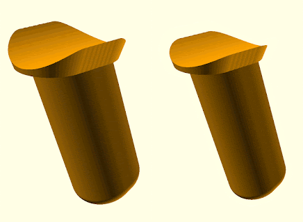
The handle felt bulky rather than sleek. The first handle to be attached was 36mm wide so that will be shrunk to 30mm. Keeping the wider handle will provide a unique tagger comfortable for someone with long fingers or large hands.
Changing the model for a narrower handle
The triple spacer used to hold the infrared LED away from the lens had an issue fitting into the forward array because of one side of the circle surrounding the whole thing. Both of the other sides were necessary to keep wires from blocking the infrared emitter so only one was removed.
Removing a side-guard of the triple spacer
The forward array, easily the most complex part, was modified to simply have a larger hole where the laser emitter was supposed to be mounted. This was designed before a laser was measured so a small hole was used with the intention of drilling it out to fit the laser. This worked but now the holes should be modeled correctly.
Forward array with laser module hole expanded -
2017-07-06 (Th) Pi0 Laser Tag PiTagErrUs
07/19/2017 at 19:20 • 0 commentsI have done chemical welding with PVC before and this seemed similar. There were two options, a yellow all-in-one glue and a black two-step procedure. In order to match the color of the pipe Medium Black ABS Cement was selected as well as some Clear Cleaner. The cleaner seemed to be diluted acetone. Since I didn't know how long it would take to set up the adhesive, rubber bands were brought with with the assumption that the parts would need to be held in place for more than a couple minutes.
ABS cement and cleanerMaterials were gathered for adhering the foregrip and handle to the ABS pipe. At first, the intention was to use high quality glue to attach the parts but some research was done and ABS cement was selected as the preferred method.
Gathered supplies for ABS cementingClear Cleaner was applied to the pipe and foregrip. This cleaner with a built-in brush could probably have been used to remove scratches from the pipe like after it had been sanded to remove the lettering.
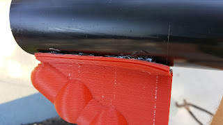
Foregrip cemented in placeABS cement set up so quickly that there was no need to clamp or band the parts in place. The black color of the cement, it was like tar, matched the pipe so at a distance there is no transition between the two pieces of plastic. For appearances sake, this seems like a very solution for the taggers when it comes to attaching plastic pieces together.
Handle cemented to pipeWithin a couple minutes, both of the grips were steady enough that they could be held by the pipe without support. The tar-thick cement did a good job of getting into the strands of the printed parts and should provide a solid bond.
Pipe and handles cemented together
 Brian McEvoy