Close
0%
0%

Robo-Dog

Develop user tracking technology and demo it using a rover robot to follow its user.

Similar projects worth following
The Robo-Dog is a proof of concept to an application requiring the implementation of a reliable user-tracking technology. The current market demand is high on this topic. There are the civil applications including smart shopping charts, factory robotic assistants, mining, toys and the military applications including personal equipment transporters and the increasing need to develop SWARM systems where a core component is system awareness of the other SWARM units in the vicinity. Therefore a reliable local tracking technology would find its use in a variety of applications. This is a research project that will demo a part of the above examples.

Introduction

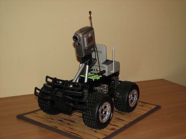
Some of the work on this technology started back in 2013, when I built a custom Robo-dog as a proof of concept. We'll call it version 1. It also became featured on Hackaday, unfortunately Mike Szczys only focused on the bluetooth remote control, a secondary feature. The user tracking tech in this project is by far more appealing:

There are several ways of tracking a user, depending on application. To start a lamp in your yard during night it is sufficient to use a PIR sensor. To create a #Robo-Dog, a system that follows its user while walking or running is a challenge requiring localisation in a 2D space.

If we take this further and try to design a SWARM system, there we'd have drones needing to be aware of each others in order to keep distance and enrol tactical plans together. There a more complicated 3D space localisation mechanism would be required.

But getting back on the ground, there are several approaches we could consider:

1. the robot has a camera, and recognises the user using some software algorithm. Eg. the color signature (simplest) or a pattern. Or the user's face (using OpenCV), or using Optical Flow to track the movement of pre-defined parts of image (eg. user's hand). This is easy, but has it's issues including dependency on lighting conditions and high processing requirements. For humans, it's the way we go to recognise others and do various actions, so this is tempting because evolution has proved it right.

2.using beacons, the user signals it's position and the robot receives the signal using some differential system (Eg. two antennas). By doing so, the robot will be able to track the source of the signal, so it knows where the user is and can track it.

3. the robot has a LIDAR and knows the environment. At start it can locate the initial position of the user, then react when the user starts moving. Surely, if the user would intersect with other actors, things could complicate even further.

4.the robot has a GPS receiver, the user has one as well, and they both intercommunicate (eg. via radio waves: bluetooth , etc), to exchange coordinates. The robot will then simply move to approach the location of the user. This is a straightforward solution, but the GPS localisation has errors, preventing use as required by this project, unless some special error-correcting mechanism is implemented in software.

Applications

A robot that can track its user is more then a toy (but imagine metallic dogs running to bring the ball back in the close future). Such a system is useful to build robot assistants in factories, carrying heavy parts and tools, in military operations carrying equipment or the wounded, automated shopping charts in malls, or even automated strollers (I recently learned how much I'd love that). The applications are endless, and so a reliable robo-dog technology would be adopted quickly to most of our daily lives.

Implementation

I will use a differential rover chassis to implement a solution to these requirements.

  • 1 × ATMega328 Microprocessors, Microcontrollers, DSPs / ARM, RISC-Based Microcontrollers
  • 4 × Motor with geared reduction
  • 1 × H-Bridge
  • 1 × UART Bluetooth HC-05
  • 1 × Sharp Infrared distance sensor

View all 9 components

  • Version 1: system ready

    Radu Motisan07/16/2017 at 19:03 0 comments

    May 03, 2013: This project finally comes to an end, so I recorded two demo videos to show the robot following me, outdoors. A few modifications in software are likely to be done, but all in one, the work is pretty much complete:

    Demo 1:

    Demo 2:

    May 22, 2013: As I am a perfectionist with all that I build, I couldn't stay away and had to make this robot even better. So I did two things:

    1) For the autonomous, human following software: I improved the ultrasonic detection algorithm, and the movement logic: Now the robot will follow its user more precisely, and the speed will vary with the detected signal: if the robots sees the user at a greater distance, will engage with a greater speed. If closer to the user, will proceed with smaller steps. The calculations are not linear, so I used some time to get the best formula. In the end I'm quite pleased, we can see some nice improvements when compared to previous two videos - so here are two new demos:
    Demo 3:

    Demo 4:

    2) For the remote control software, where the user controls the robot using a phone, the rover now reports its frontal sensor readings (that show the proximity in centimeters to any detected obstacle), to the smartphone. So the movement commands go from phone to robot, and the sensor readings go the opposite way, from robot to phone. The Android software now allows the user to turn the lights on and off, and using the frontal distance sensor, a red line is drawn, showing the proximity to an obstacle. The robot can be controlled this way - without actually seeing what it is heading for, as this simple radar will be enough to get a clear path. Here is another demo:

    3) When bluetooth is connected, the robot will ignore any ultrasonic signals from its beacon. So better separates the two modes of operation discussed above.

    Resources:

    Mechanisms for Combining Infrared and Ultrasound Signals for Indoor Wireless localization
    Infrared / Ultrasonic beacon
    Ultrasonic Source Localization
    Mobile Robot Navigation
    Learn about GPS

    Robo-Dog on Hack A Day

  • Version 1: ultrasonic beacon

    Radu Motisan07/16/2017 at 19:02 0 comments

    May 01, 2013: Time has come to build the TX ultrasonic beacon. This time I wanted to try something new, so here is my first PCB for SMD components:

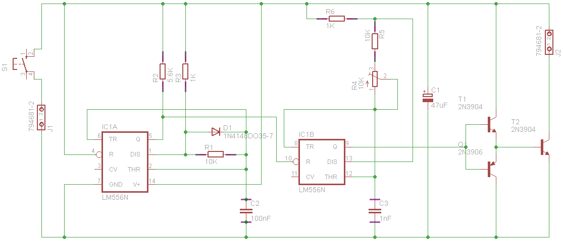
    It uses a NE556, dual timer, and is configured to emit short bursts of 40KHz pulses. You can see the circuit here:Eagle file also available, beacon TX.
    A case was also needed, to enclose the 9V battery as well, and make it comfortable for holding it in the hand. The final results looks like this:


  • Version 1: Perfecting the design

    Radu Motisan07/16/2017 at 18:58 0 comments

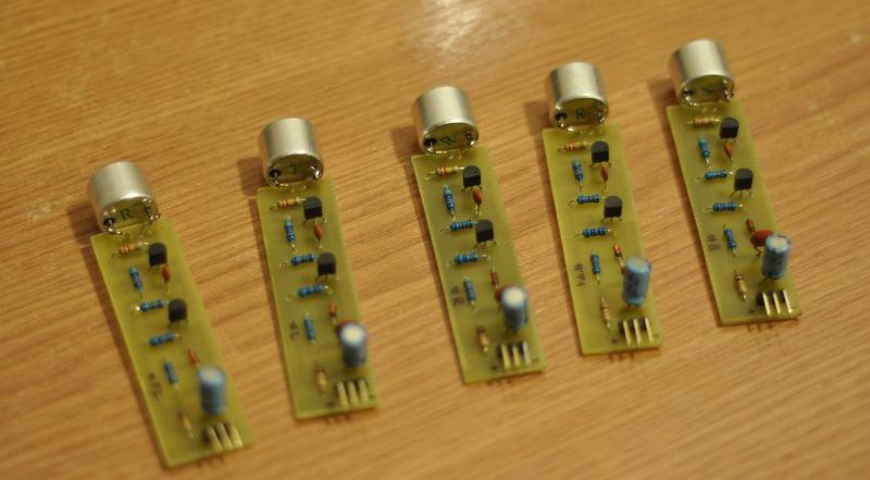
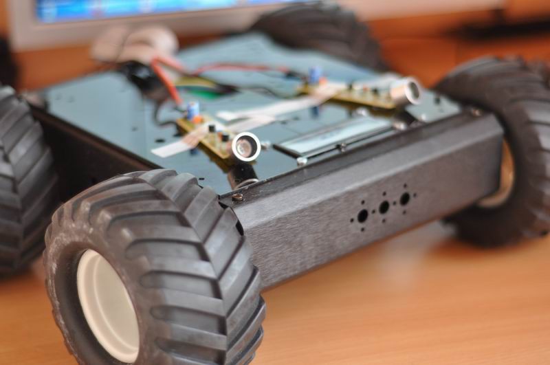
    April 10, 2013: I built a total of 5 ultrasonic receivers, that are to be placed two in the front, one at the back and two on each side.

    The idea is to have the robot turn around facing the ultrasonic signal, and then to make it follow the source using the two frontal sensors. The differential readings will help us decide whether to adjust the direction for left or right.
    Using some PVC pipes, I built some nice and robust plastic enclosures, by heating and pressing the plastic to get the desired shapes:

    The result looks great:

    For some uber-coolness factor, I decided to add frontal white lights and back position red lights, controllable from the software (on/off). The frontal side now also houses a nice Sharp 2y0a infrared sensor, that will help avoid hitting any obstacles. So now the robot is capable to hear and see its surroundings. Love how it looks:


  • Version 1: Success!

    Radu Motisan07/16/2017 at 18:52 0 comments

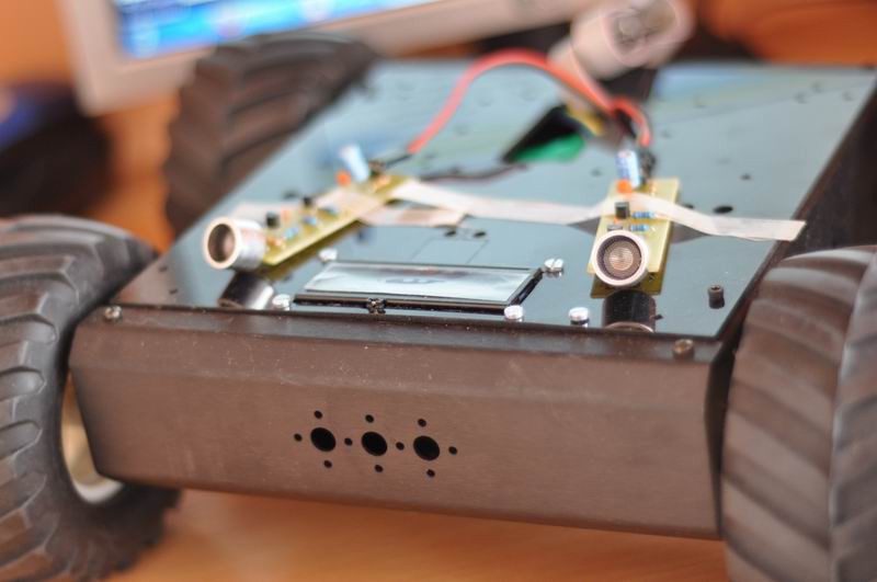
    April 09, 2013: Using the ultrasonic sensors differential readings (with sensors placed in front, at angles of aprox. 15 degrees of the longitudinal axis), I got some excellent results: the robot is able to follow me, and keep track of my speed, and orientation:

    The algorithm compares the readings from the two sensors and decides whether to turn left (if left sensor return higher readings), right or to move forward (if the output of the two sensors is similar).
    There are some remaining issues:
    - if the robot approaches a wall, and the beacon signal is coming from the back, it will reflect in the wall and confuse the robot
    - no detection capabilities for signal coming from any other direction, other than the front
    To solve these issues, three more ultrasonic receiver boards are needed, namely one for back, and one for each of the sides. Also the movement is a bit shaky, and this can also be improved by changes in the robot's software code. More to follow soon.

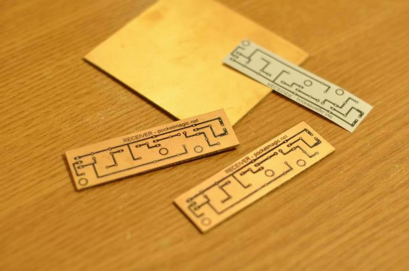
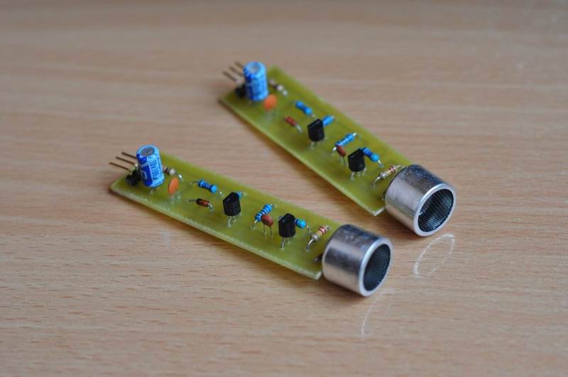
    I built some nice PCBs for the ultrasonic sensors, and provided more details on Detecting an ultrasonic beacon, here.


  • Version 1: GPS Errors and the ultrasounds solution

    Radu Motisan07/16/2017 at 18:50 0 comments

    April 08, 2013: As I've shown previousl, the purpose of this robot is to follow its user, and I imagined two instruments for implementing that:

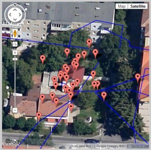
    1) a global localization method, using GPS. The PROs are that we can place a GPS module on the robot, and the user can have a mobile phone with its own GPS module. The phone can establish a connection to the robot using Bluetooth, and send the user coordinates periodically. Then the robot can calculate the path it needs to run, to get in close proximity of the user, and follow him/her. Sounds good, but the CONs are bad: first, the GPS errors are too big to allow us to make the robot follow the user; it would rather jump like a crazy monkey all around the user, and this is the best scenario. Another issue is also the GPS signal which is poor or unavailable indoors.
    If we place a stationary GPS receiver, here's how the GPS coordinates look like:
    gps_errors
    As you can see, despite the fact our GPS receiver is stationary, the localization data we receive has a tolerance of a few meters or even tens of meters, placing us on a disc surrounding the real position. This is inappropriate for the purpose of this work, so I have decided to find different means of robot positioning and orientation; this number -2- below:2) The local method will use a closed system for localization, formed of only the robot itself, the user, and a signaling beacon. Normally the user will carry a signaling beacon (ultrasonic, infrared, radio, etc), which the robot will "see" and follow. Easy to say, doing it is of course much harder, as we need a smooth robot movement, so a lot of error compensation and fuzzy logic must be involved.Recently I made some excellent progress using ultrasounds as a transmission method, to create a simple beacon detector. You can read more on it here.

    The user needs to carry this tiny, low power ultrasonic beacon which the robot should be able to "hear" and use the signal to navigate to the target, and follow it.

    These wonderful modules will not only return a signal when ultrasounds are detected, but the output amplitude is directly proportional with the actual distance to the beacon. So we'll know both where the beacon is, and how far.
    Given these tools, there are several ways of implementing the working mechanism:
    a) using a single ultrasonic receiver, placed in front of the robot: the rover will need to rotate until it detects a maximum level of signal. Then it should move forward until the detected signal reaches a given threshold (so it will not hit the user, but stop right before him/her). It doesn't really work well, as the software gets overcomplicated and the results are not as good as expected.
    b) similar to a), but use a servo motor to rotate the ultrasonic sensor instead of rotating the entire robot. When the maximum signal is detected, the robot should turn towards the source, and begin moving forward . It still doesn't solve many of the issues found with a)
    c) using two ultrasonic receivers, placed some space apart, in the frontal part of the rover. Now we can make differential measurements, so it's easy to know from which part is the signal coming from, as the corresponding sensor will have higher readings. The robot can now directly turn towards the beacon, and follow the forward direction while the two sensors give approximately similar readings. If the right sensor output increases, then it means the robot needs to turn right, to face the beacon and continue moving forward. Same case for left. A similar approach has been used in a project by Andrew Wiens .

    d) using more than two sensors, ideally 8, placed at 45 degrees in a radial disposition. This would pinpoint the source more accurately, and reduce the time needed to find the beacon. Still, to simplify, I plan to go for the differential measurements presented at c) .

    The ultrasonic sensors already return an output signal which is a function of the distance to the beacon / user. This can be used to measure the distance. If greater accuracy...

    Read more »

  • Version 1: Bluetooth remote control

    Radu Motisan07/16/2017 at 18:46 0 comments

    March 28, 2013: Following the successful dual HBridge integration, I added the Bluetooth UART module, and wrote a software for Android OS, to allow me to control the robot by using the phone. Here's a demo video:

    And a few pictures to show the final robot shape:

    Next thing to do is to make the robot follow the user, AUTOMATICALLY! I'm currently considering two options, one involves using the GPS Module, send the coordinates via bluetooth to user's mobile phone that also has GPS and can then inform the robot where it needs to go, the second option would be to use some kind of beacons, the user would carry in his/her hand (or pocket), and the robot would detect those and follow the signal.

  • Version 1: The H-Bridge

    Radu Motisan07/16/2017 at 18:42 0 comments

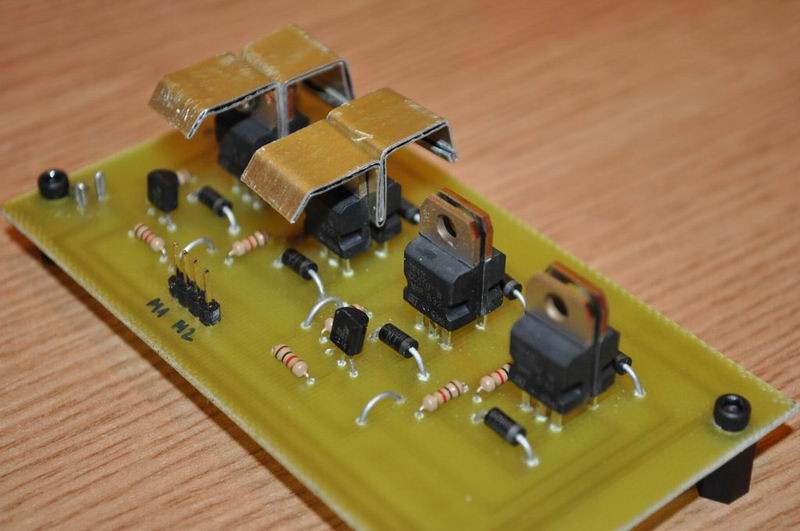
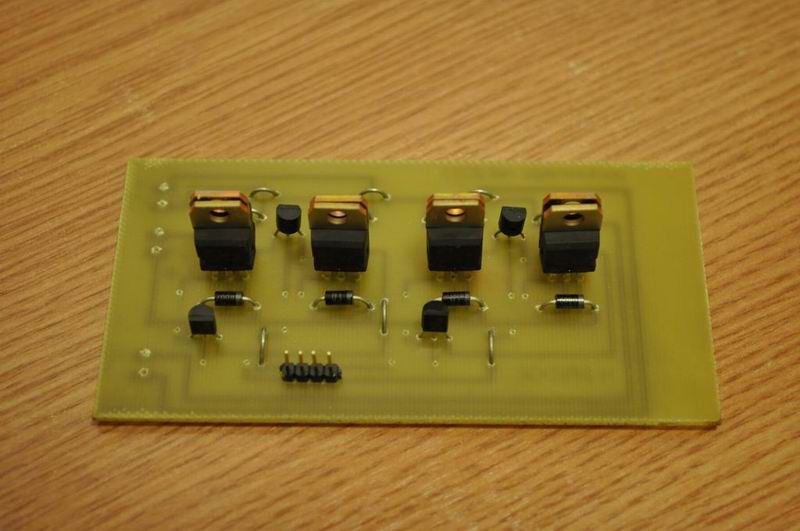
    March 27, 2013: The Sabertooth 2X12 R/C Regenerative Dual Channel Motor Controller needs to be hooked up to an UART port. On the microcontroller board I have no free UART port available, so to simplify I plan to use a dual H-Bridge built from scratch. You can see the Dual H-Bridge here.

    Schematics and PCB available in the Dual H-Bridge article.

    The LCD has been mounted inside the chassis, must admit it looks perfect this way: low profile, high tires, black paint, and that blue electric LCD light. All combined with a highly energetic movement.

  • Version 1: GPS/Bluetooth Interference

    Radu Motisan07/16/2017 at 18:39 0 comments

    February 25, 2013: I finished the top board, exposing the bluetooth UART module and the NMEA GPS module. This will be mounted outside the robot's body, to make sure the modules get maximum radio signal. An LCD is to provide vital information such as battery levels and other diagnosis messages.

    And with these last modules, I had to write a considerable amount of software. And this is only the beginning of the long road ahead:
    - HD44780 LCD code . The LCD uses only 3 wires to connect to the Atmega128, using a shift register, 74HC164, to save a few IO pins.
    - UART code, to handle data from the UART Bluetooth module and the UART GPS Module.
    - GPS NMEA Parser, highly optimized to save memory and processing power. Also available on Google code, here.
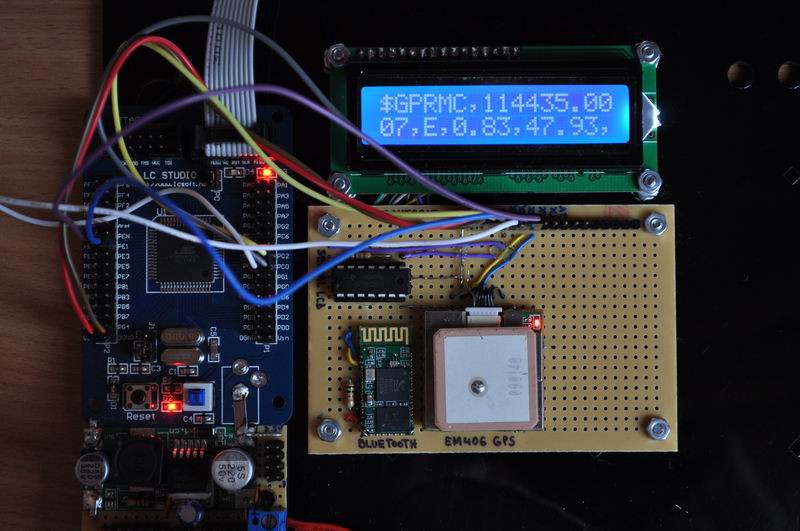
    And the first problems didn't wait too long to show up. It appears the bluetooth module's RF creates some kind of interference that reduces the GPS signal. As a result, having the Bluetooth module on, I can barely get a GPS fix. When the signal is good (8 satellites in use), turning the bluetooth module on will reduce the signal (3-4 satellites). Here is a demo to show this defect. The red jumper wire is used to power on/off the Bluetooth module. The "sats" value displayed on the LCD is the number of fixed satellites.
    So to bypass the issue, I'll need to rework the top-board and move the Bluetooth module at some distance from the GPS module. I was not aware of such a design requirement.

  • Version 1: The Atmega128 microcontroller

    Radu Motisan07/16/2017 at 18:33 0 comments

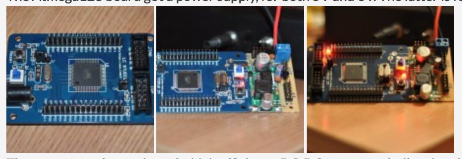
    February 12, 2013: The Atmega128 board got a power supply, for both 5V and 3V. The latter is for the Bluetooth module and one of the GPS modules.

    The power supply consists of a high efficiency DC-DC converter built using the LM2596 IC. There are plenty of such converters available on Ebay for just a few bucks. I replaced the pot with a fixed 1KO resistor, so the converter would put out a fixed 5V voltage. The 3V is obtained using two L78L33 's. The power boards where fixed to the Atmega128 board.

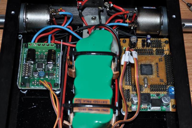
    February 18, 2013: New Atmega128 board, with pin connectors including power and gnd to make connections easier. The microcontroller board has been mounted to the robot's platform. The Sabertooth 2X12 has also been mounted. Thick wires link the h-bridge and the motors.

  • Version 1: assembling the chassis

    Radu Motisan07/16/2017 at 18:27 0 comments

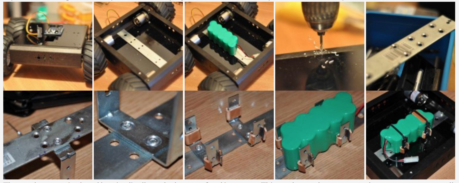
    February 06, 2013: The rover's bottom is a thin black plexiglass sheet, that looks great but can't sustain much weight. In this case, the battery seemed a bit too heavy for the bottom sheet, especially considering high speed movements over rough terrain. So I had to build a battery holder using some steel. Hope I won't get to replace all the original rover by the end of this project :) . But this is what perfectionists usually do

    The steel support is placed longitudinally at the bottom, fixed in screws. This can be used to support other components as well, as I drilled multiple holes for that. Two U-shape holders have been fitted using rivets, this way I got no difference in level, and no sharp points to puncture the battery to be placed in this support:

    The prominent ends have been leveled with a metal file. The U-shaped holders got some little plastic spacers, made from PVC plastic heated and bended in a convenient angle. With the battery in place, here is the first motor test:

View all 11 project logs

  • 1
    The Rover platform

    Assemble a robot. It can be anything with wheels that moves: either you build one from scratch, you convert a toy or get a dedicated platform. Ideally it should be able to keep pace with a running human.

    Personally I go for 4WD rovers, where each wheel has its own motor (with reducer), and a strong H-Bridge capable of higher current. The movement must be differential, to allow on spot turn around. 

  • 2
    The electronics

    A microcontroller board and a dual h-bridge is needed to control movement. 

    The code I prepared is for Atmel microcontrollers, specifically the ATMEGA328. Go for that if you like, as the code on Github is all set for that. 

    Additionally you can add a serial Bluetooth adapter , that is to be able to control the robot using your Android phone as a remote. Source code for that is on Github too.

  • 3
    The Ultrasonic localization

    Build at least two ultrasonic receivers (PCB design files are on Github), and place them at the frond of the robot.

     If you want to increase it's sensing capabilities, add more of these, and adjust the code accordingly. You're pretty much done at this step, congrats on building a robo-dog!

View all 3 instructions

Enjoy this project?

Share

Discussions

shameslee5 wrote 07/06/2023 at 12:00 point

hey thats great, my father is an automobile engineer he made a dog that works with Ai(code) the commands like to open door come here etc it seem like this.

  Are you sure? yes | no

craig2tom wrote 02/21/2022 at 20:27 point

Wonderful idea to run the program with Pet algorithem. I have seen similar program on yoursilverlab

  Are you sure? yes | no

hisyamil95ramble wrote 09/29/2018 at 18:29 point

hye bro..i am electronic engineering student..actually i'm interested in your project and i want to apply to my final year project..can you help me out?

  Are you sure? yes | no

Dennis wrote 08/04/2017 at 01:08 point

That is one cool bot!

  Are you sure? yes | no

Radu Motisan wrote 08/04/2017 at 06:50 point

Thanks @Dennis !

  Are you sure? yes | no

Radu Motisan wrote 08/03/2017 at 16:58 point

Hi @Simon Merrett , thanks, there's definitely a big need for improvements, keep the good ideas coming!

  Are you sure? yes | no

Orlando Hoilett wrote 07/31/2017 at 22:24 point

Cool. I was trying to build a follow-me robot dog last summer. I wish I found your project last year so I didn't have to start from scratch. Nice, fluid, "follow-me" function. Good stuff.

  Are you sure? yes | no

Radu Motisan wrote 07/31/2017 at 22:26 point

Thanks. Wait till you see the improvements I am working on.

  Are you sure? yes | no

Orlando Hoilett wrote 08/13/2017 at 20:44 point

Look forward to it.

  Are you sure? yes | no

Simon Merrett wrote 07/18/2017 at 13:04 point

Radu, have you considered adding a ranging element to this sensor array? On the Dtto hangout we discussed this idea which is mentioned in swarm robotics papers. You would compare the difference in time of arrival of a synchronously transmitted audio and rf/light signal. As you are already dealing with what I would consider the harder of these two, the sound signals, this may be a marginal additional effort for significant performance gains. For example, you can perhaps modulate the robot speed to maintain a preset standoff. This could be PID controlled. This feature may help prevent the robot from falling behind and out of sonic range of the leader. Great project! 

  Are you sure? yes | no

Radu Motisan wrote 07/23/2017 at 12:10 point

Thanks Simon, I thought about that, and concluded that two differential antennas mounted on a robot like this are too close to each other to be able to sense the time differences based on wave-time-of-flight, including with time encoded in the radio signal. Do you have any idea on this?  The robot speed adjustment already works!

  Are you sure? yes | no

Simon Merrett wrote 07/23/2017 at 14:04 point

Yes, the comparison is not between two waves of the same medium but between one rf/light  and one sound. So send your ultrasonic pulse at the same time as another pulse from eg IR LED or NRF24L01. Then Robo-Dog just compares the arrival times of the sound signal and the rf/light signal. Does that make sense? 

  Are you sure? yes | no

Ted Yapo wrote 07/23/2017 at 14:09 point

@Simon Merrett

It's like estimating how far away a lightning strike is by counting the time between the flash and the sound of thunder.

  Are you sure? yes | no

Radu Motisan wrote 07/23/2017 at 14:13 point

Got it now, thanks guys :) . I can already estimate the distance to the user, as the amplitude of received Ultrasonic signal is proportional to distance. 

  Are you sure? yes | no

Simon Merrett wrote 07/24/2017 at 17:29 point

@Ted Yapo , that's right. 

@Radu Motisan , that's cool that you have a simpler method. One possible advantage of this method would allow for people walking between you and Robo-Dog and perhaps help with obstacle avoidance (although I haven't fully thought that through, just thinking of static objects between the user and Robo-Dog).

  Are you sure? yes | no

Similar Projects

Does this project spark your interest?

Become a member to follow this project and never miss any updates