Charles Galambos
-
Motor Controller Testing
07/21/2017 at 18:17 • 0 commentsFirst up was getting the angle calibration working. This involved using six-phase control and measuring the reading from the Hall sensors, then linearly interpolating between the angles.
Once the angle sensing was working it is then possible to run the motor. It works well, if a little noisily.
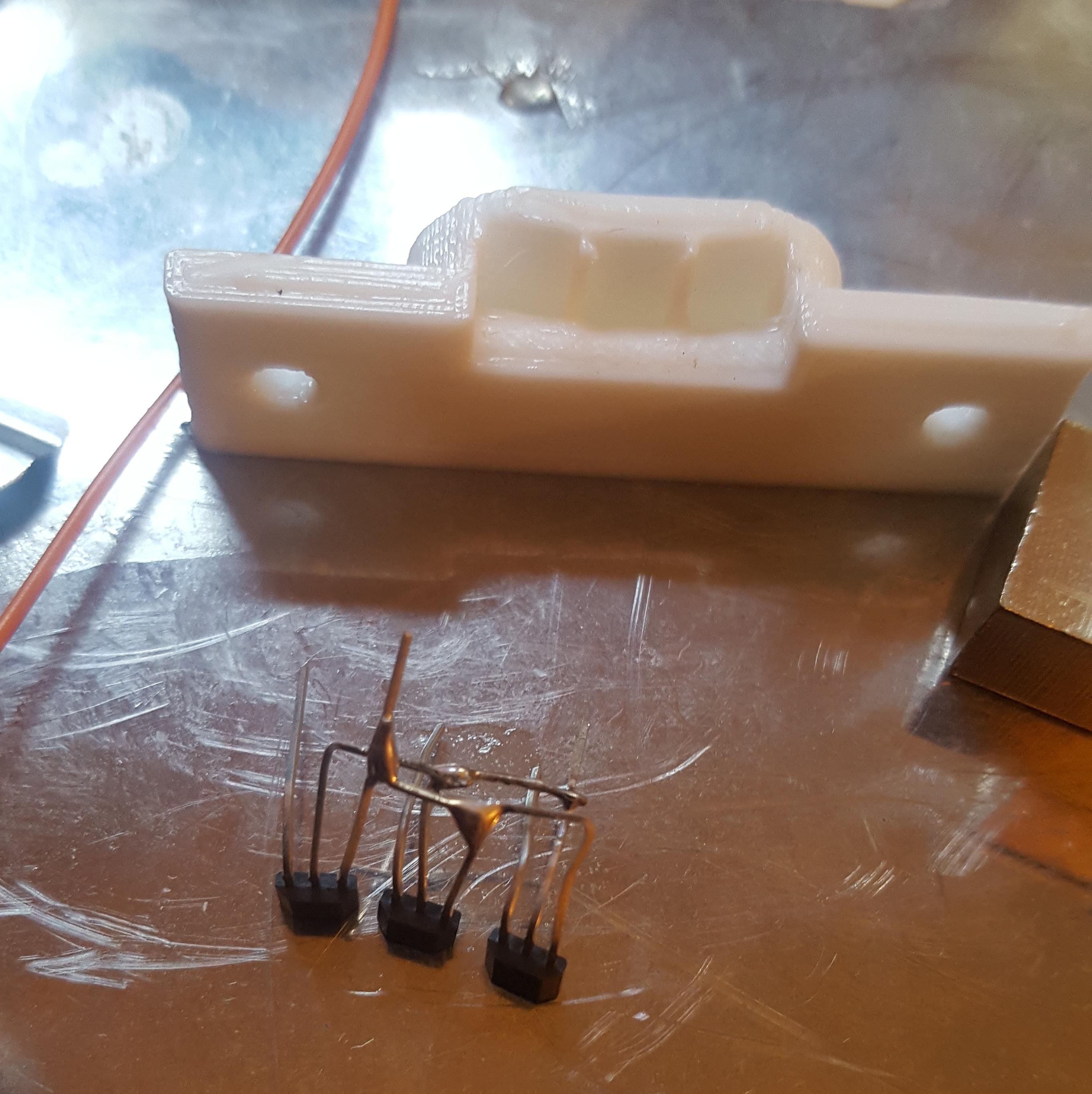
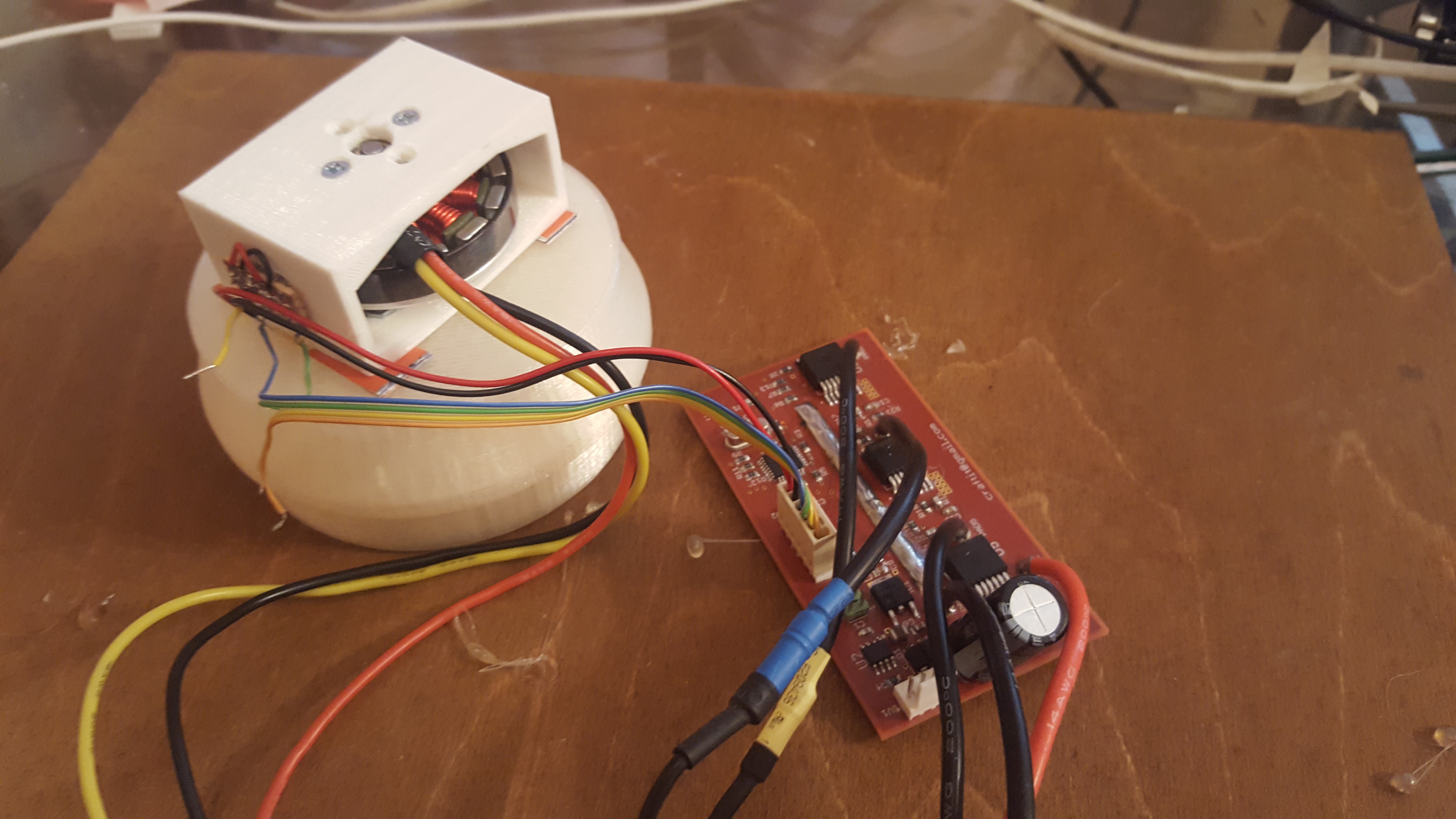
Assembling up the 3 linear Hall effect sensors for testing the motor controller.
![]()
Finally the motor is running, the firmware still has a long way to go though.
-
Motor Controller Mk II
07/21/2017 at 17:56 • 0 commentsThe second version of the motor controller is based on a much more powerful ARM chip.
The design owes much to the open-source motor controller designs at http://vedder.se/2015/01/vesc-open-source-esc/, and https://hackaday.io/project/11583-odrive-high-performance-motor-control
If this wasn’t a project about learning and experimenting, ideally it would have been better to just use one of these designs. But they used shaft encoders, and/or didn’t seem optimised for driving motors at low speeds, at least at the time.
I did want to learn and experiment, and I wanted a new controller design which would drive bigger motors, with more precision, alongside other requirements such as CAN bus communication.
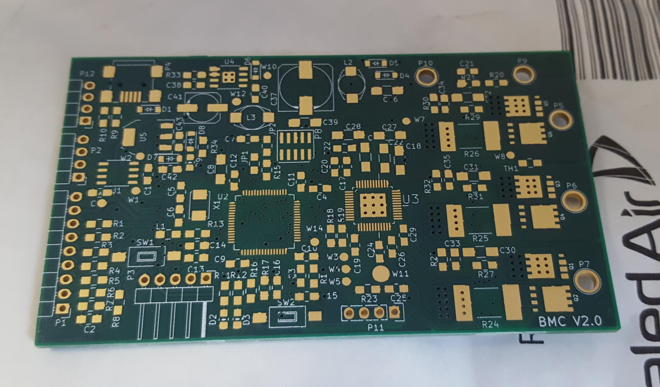
Here is the empty PCB as it arrived.
![]()
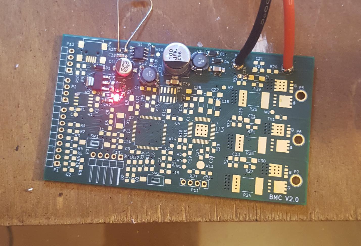
The first thing I did was populate the power supply, and check it was delivering the right voltages to the right places. This is much easier to do when nothing else is connected. As you can see the red power led is happily illuminated.![]()
Next I populated the micro-controller. Things powered up, and no excess current draw, a good sign!
![]()
Next to hook it up to the programmer and see if we can get a LED to blink..
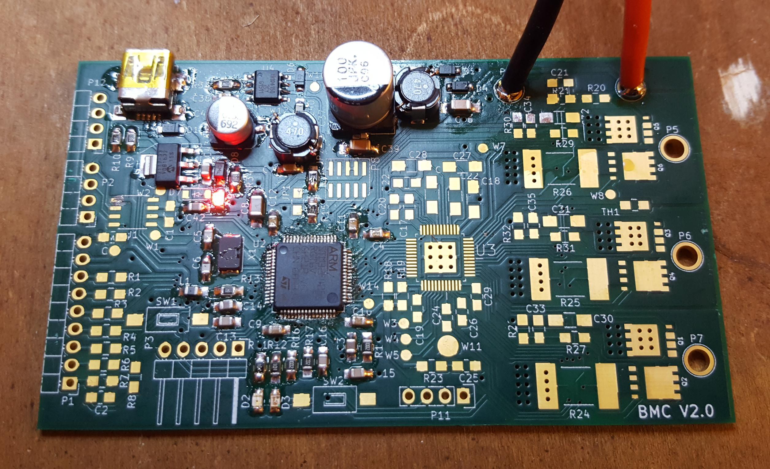
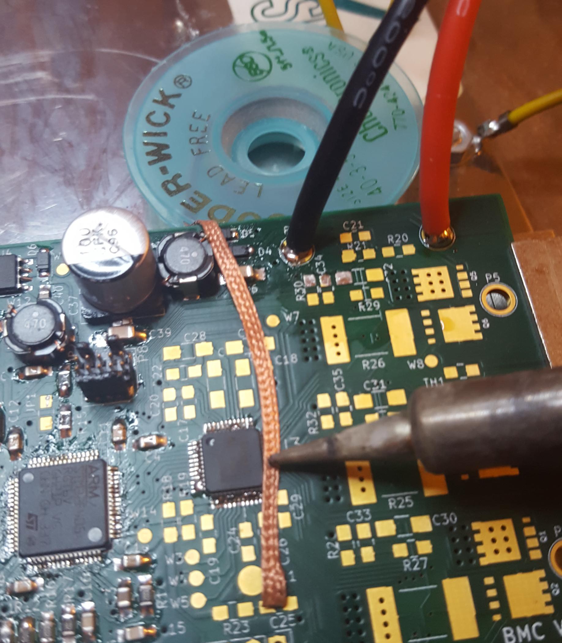
Next I fitted the rest of the electronic in the driver section. Soldering the large chips was tricky, essentially I ended up using as little solder paste as I could with a hot air gun. This would inevitable leave solder bridges between some of the pins of the chip, so I would then remove the excess solder away with solder wick.
![]()
The board with everything but a few connectors fitted.
![]()
-
More Legs
07/21/2017 at 17:11 • 0 commentsThough the motor controller isn’t ready, I tested a leg by fixing the drive spline and putting vertical force on the leg.
The motors tended to twist, so the hips needed extra reinforcement. The reinforcements were extended to add a front bumper. There is still a little bit more twisting than I would like, making the legs springy at small angles, how much this will affects the legs in walking isn’t clear.
Some of the clamp joins also gave, hopefully a combination of tightening and some hot glue to increase friction will sort this out.
With motors on the hips dropped lower, another worry is the clearance between the motor mounts on the legs.
![]()
One of the design changes that came from this was to round off the corners on the motor mounts as it improves the range of movement noticeably.
-
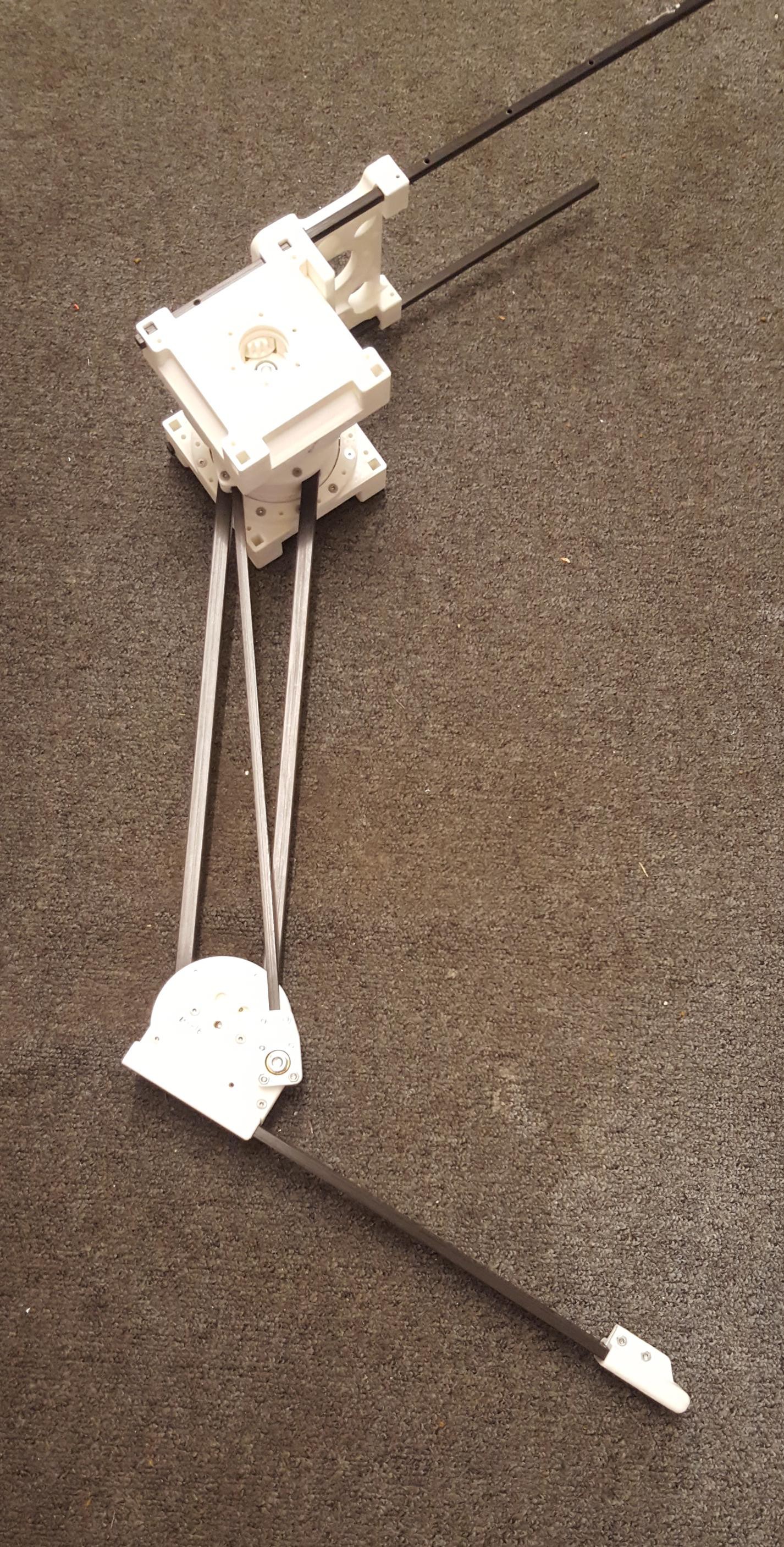
Hips
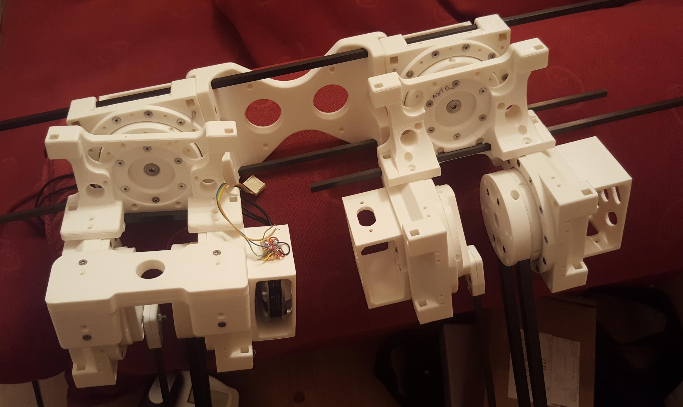
07/21/2017 at 16:52 • 0 commentsOriginally the design had the two motors controlling the upper and lower leg position in line with the hip motor. This design was compact, but had the problem that it severely limited the range of motion of the upper leg. To allow the upper legs a full range of movement back and forward it was necessary to lower the motors, allowing the upper leg a full 180 degrees of motion.
The hip joints are of a composite design using carbon fibre rods to reinforce the 3d printed plastic parts. How well this works we’ll see when the robot starts walking.
![]()
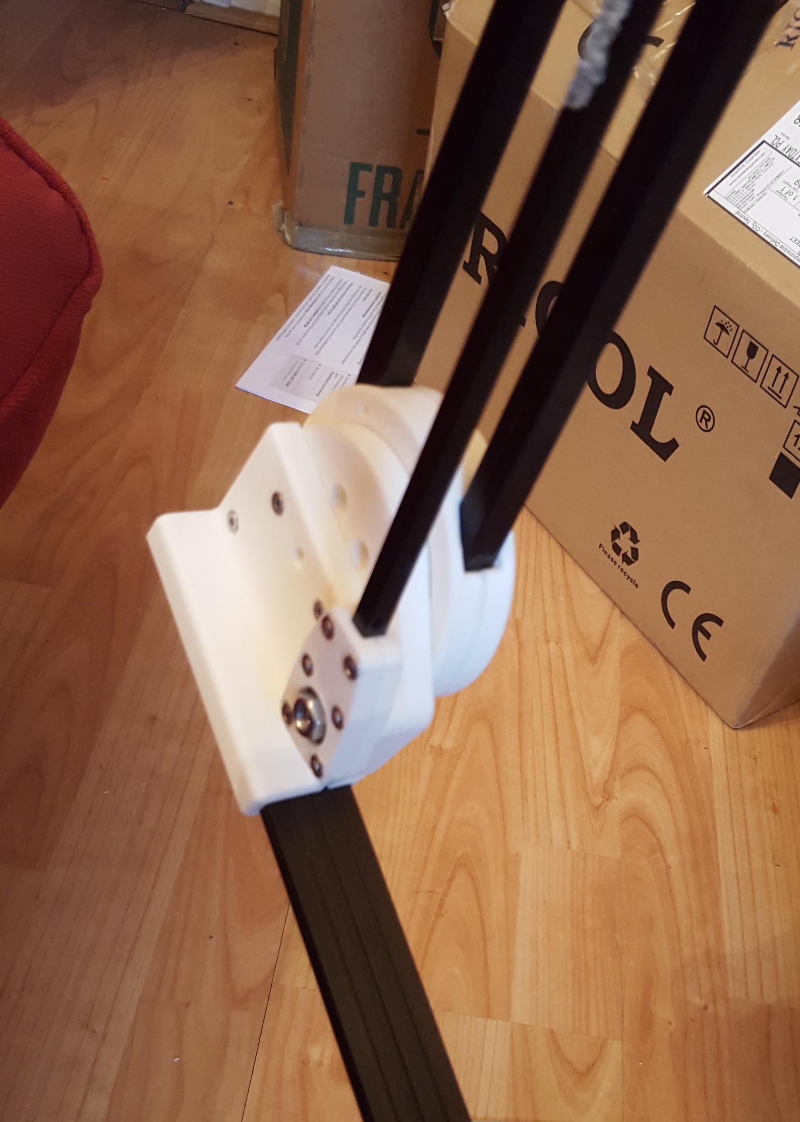
In the following picture you can see how the carbon links the two parts. When fully assembled there is also a rod threaded vertically.
![]()
Side view of the assembled leg, the vertical rods haven't been trimmed to size yet.
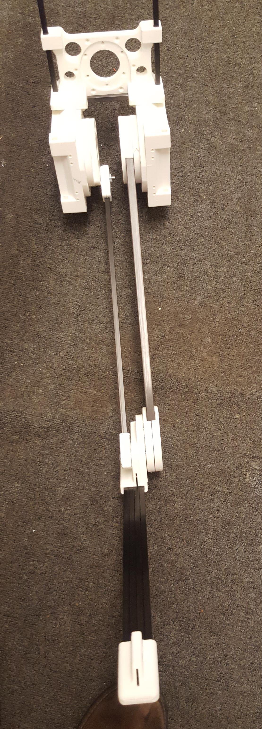
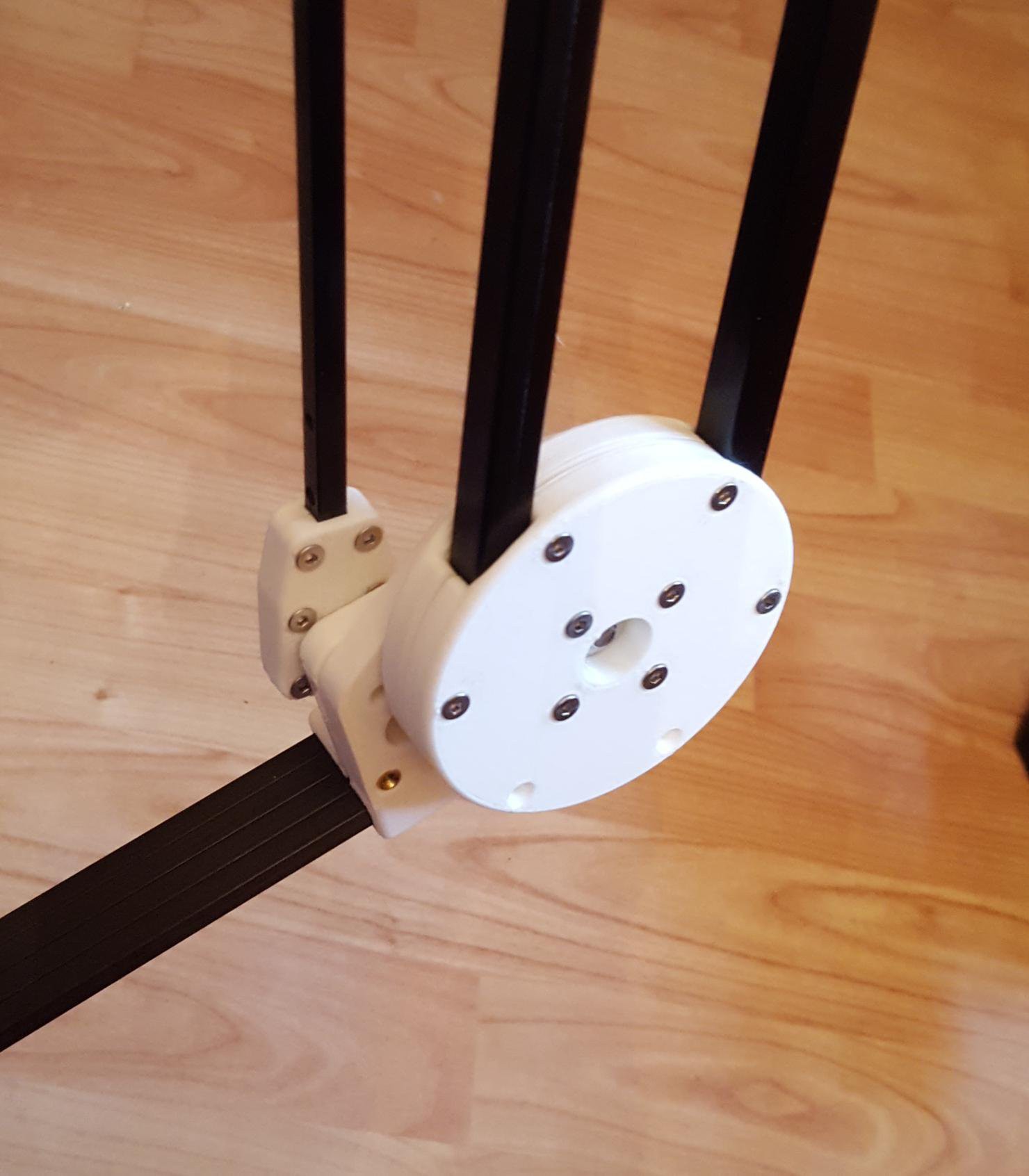
![]()
Front view of the assembled leg
![]()
-
Legs and Knee
07/21/2017 at 16:35 • 0 commentsThe design of the robot aims to keep the weight of the motors at the top of the leg, this is to keep their moment of inertia low so they can be swung back and forward quickly, improving the robot’s agility
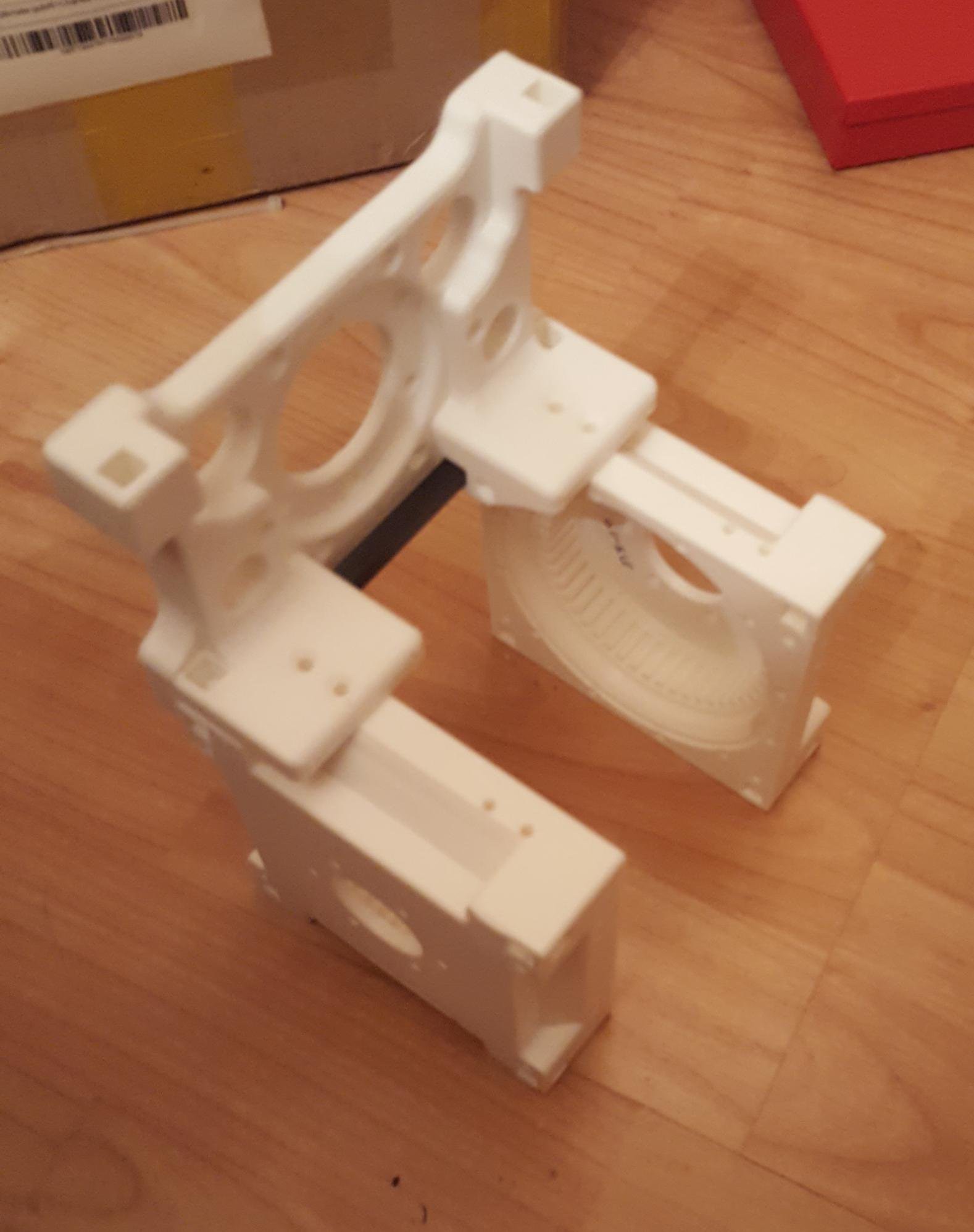
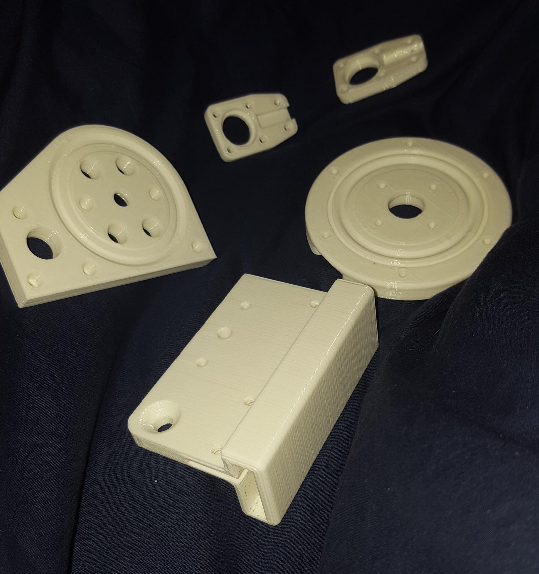
The knee joint is another place that has to pivot whilst taking bending forces. The design ended up using both off the shelf bearings for the vertical load, in combination with another plastic bearing to take the bending forces.
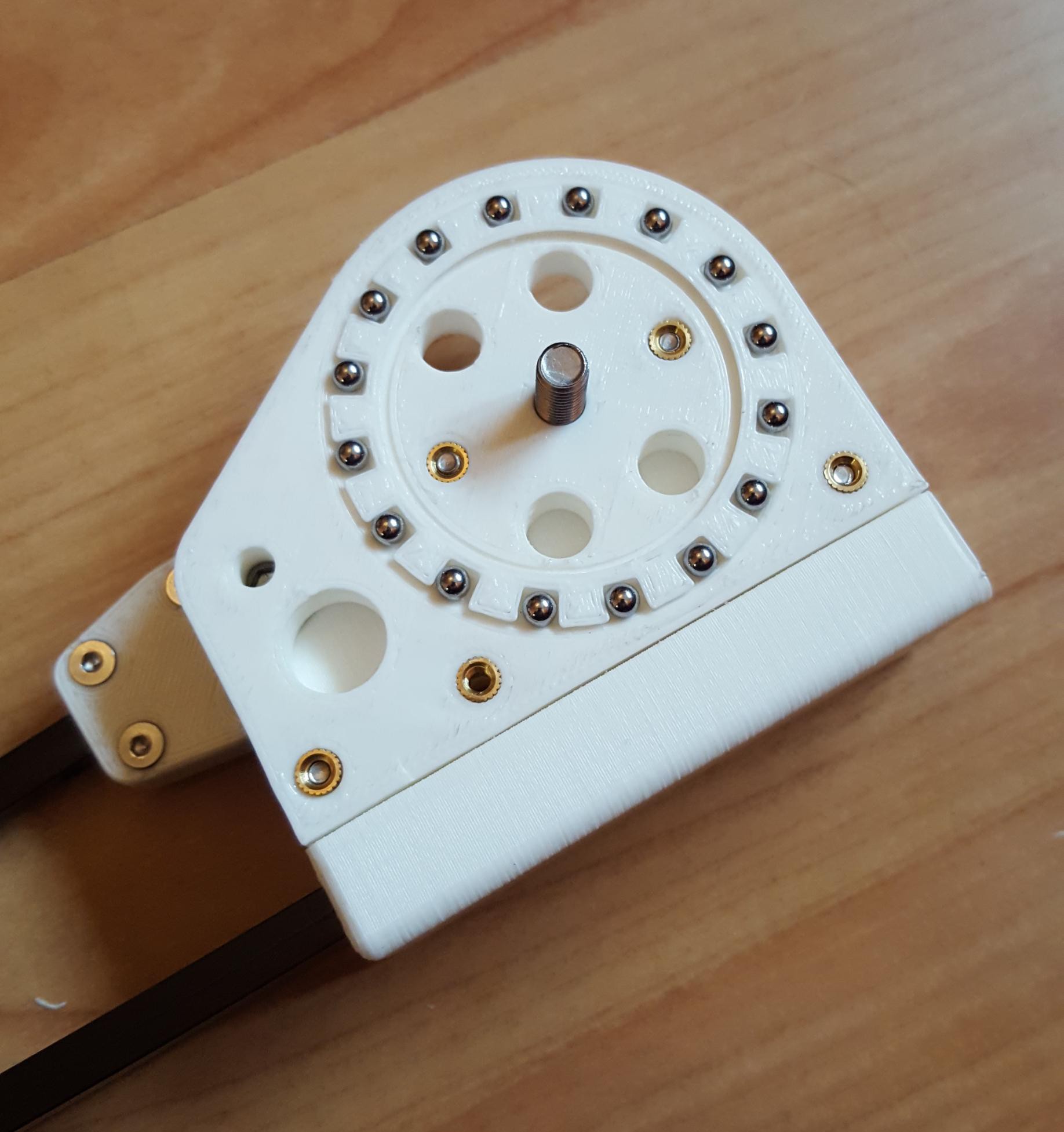
The parts of a knee joint
![]()
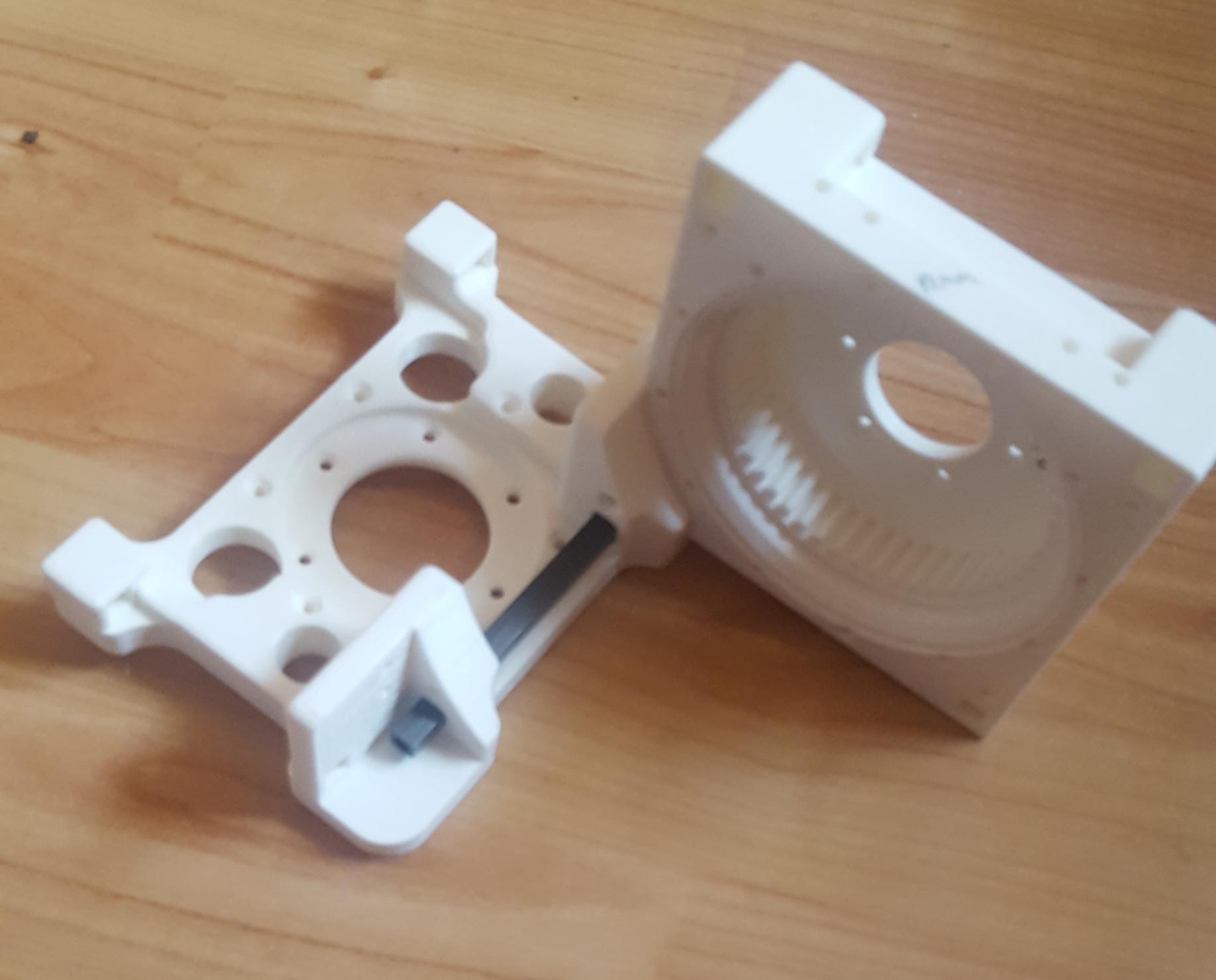
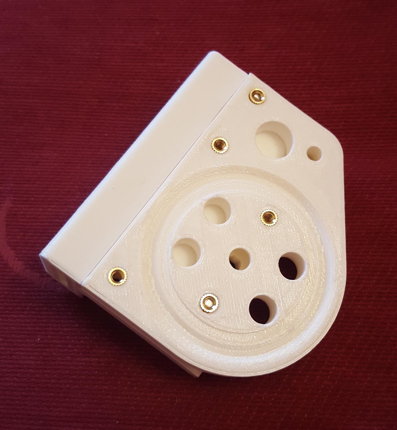
Lower half of the knee
![]()
The lower half of the knee with bearing cage and ball bearings.![]()
The assembled knee![]()
![]()
-
Prototype Motor Controller
07/21/2017 at 16:14 • 0 commentsInitially I was intending to use the brushless motors like stepper motors, hoping to get the weight advantage over normal stepper motors. How hard can controlling a motor be? This is one of those rabbit holes, the more you go into it the more you discover there is.
One thing I quickly realised is that to run brushless motors efficiently at low speeds some kind of position feedback would be needed. If you ran them like stepper motors the batteries of the robot would be flat in no time, and motor windings would overheat.
One common technique of driving brushless motors is to use Hall effect switches, these sense the position of the motor and allow you to choose the correct winding to power ratio. The problem with this is the information about the rotor position is quite coarse. Typically if you want finer position information you would use a shaft encoder, but after a bit of research I found them to be quite expensive and bulky. So I experimented with changing the magnetic Hall effect switches to linear Hall sensors. The wave form out of these sensors looks like a truncated saw tooth, and if you position the sensors carefully the linear region overlaps. The other worry was the current in the windings would interfere with the signal, but an experiment looking at the position signal while the motor was being run indicated that the readings remained stable.
The first motor controller I designed used an AVR, and integrated mosfet drivers. It worked, and drove the motor well, but getting the software to work reliably above around 5 kHz with all the feedback I wanted proved tricky, and so the motor was very noisy. It is also around this time I came across ‘Field Oriented Control’, which the humble 20 MHz AVR wasn’t up to.
I also found getting good angular position sensing reliably from two Hall sensors was tricky, so I decided to move to 3 Hall sensors get better coverage.
Here you can see the motor controller attached to the gearbox
![]()
Early tests running the motor with the 3d printed gearbox.
In this video you can see the planetary gears in action.
-
Designing The Gearbox
07/21/2017 at 16:02 • 0 commentsIdeally I would use a large diameter brushless motor directly, but doing the sums the brushless motors in my price range just couldn’t provide enough torque, and again, I want to put together an affordable project.
The ghost Minitaur is great, https://www.youtube.com/watch?v=_YrWX9ez3jM, but the motors are just too big and expensive relative to the body.
So a compact gearbox was needed, and a planetary gearbox seemed the ideal solution.
The design was inspired by some of the planetary gearboxes on thingiverse, such as the example at https://www.thingiverse.com/thing:8460
I ran a variety of experiments with planetary gearboxes for the servo. The original gearbox had a ratio of about 40:1, though this was later dropped to 21:1.
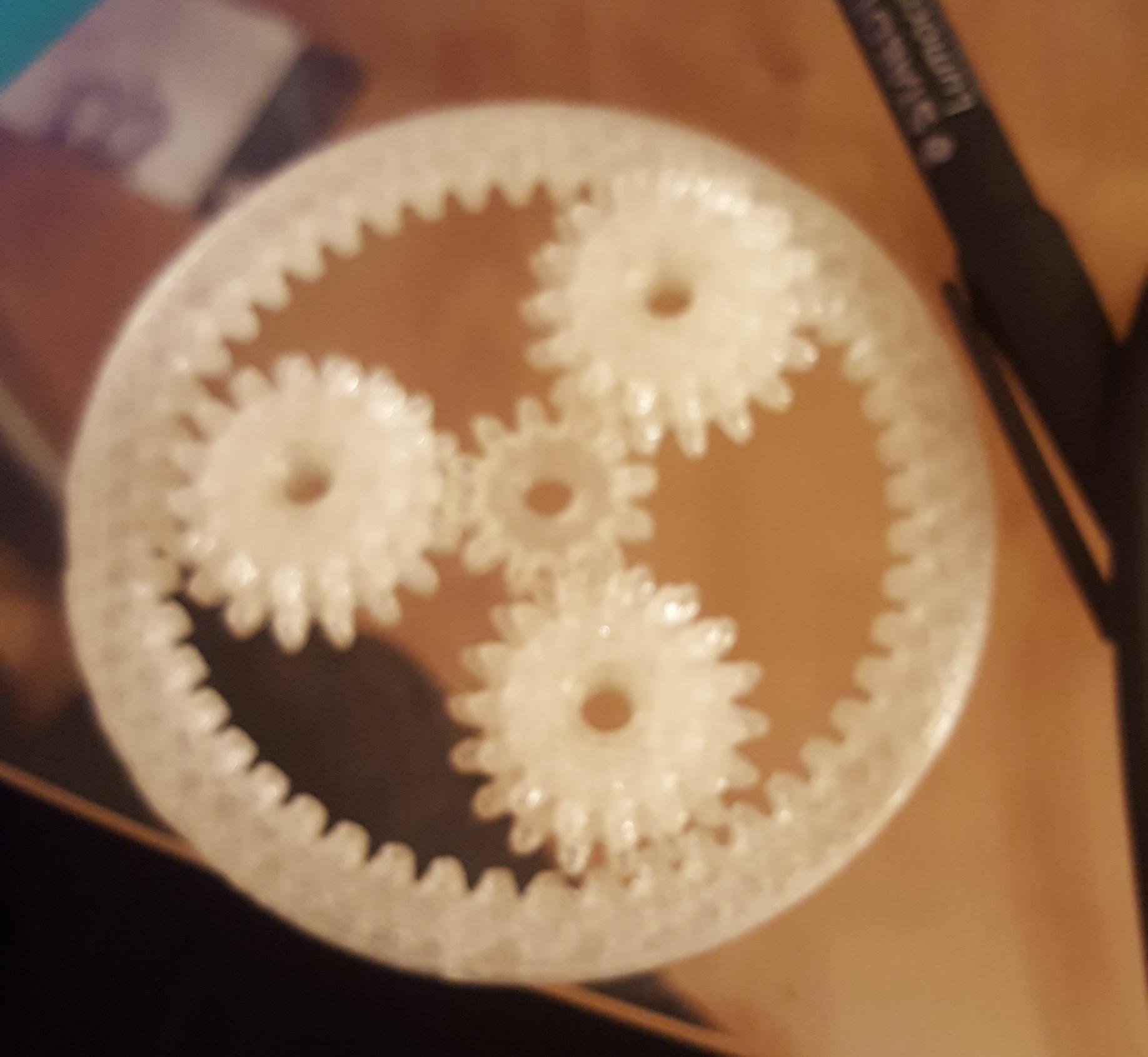
First I printed some experimental planetary gear to check they would fit and mesh correctly.![]()
The two halves of the prototype gear assembly

Planetary gears
![]()
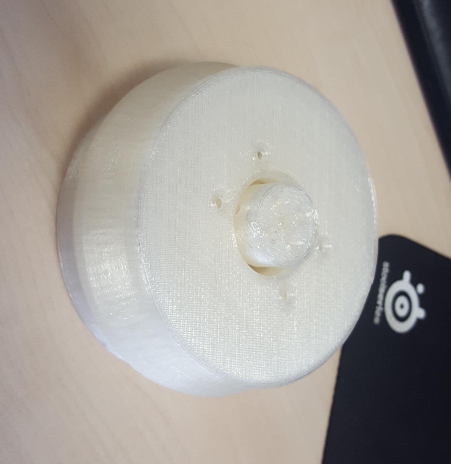
The assembled unit.
![]()
-
Driving the robot
07/21/2017 at 15:27 • 0 commentsBrushless motors have an excellent power to weight ratio, and with the advent of quadcopters and electric flight have become relatively cheap. The idea was to leverage this for DogBot. The first design was a linear actuator, with a brushless motor driving a threaded rod.
The main problem with this is that it is too slow and wouldn’t be back-drivable or compliant. This means you would need separate sensors to measure the force applied by the actuator. Linear actuators are also quite large
DogBot needs a fast response time that is suitable for reacting to sensor feedback - it has to be sufficient to enable movement for balancing on rough terrain etc.
-
Initial design
07/21/2017 at 15:24 • 0 commentsDogBot was originally going to be a hexapod, but that would have meant the increased costs of 50% more motors and electronics, in exchange for the extra functionality. Given DogBot is supposed to represent an affordable end-to-end solution, a quadruped was chosen.
The scale of the robot is such that it can move around human-scale environments autonomously: specifically the field at EMF camp to start with. Originally the aim was to get something working for EMF camp 2016, so the project overran slightly!
The legs were designed so that there is a position where the dogbot can stand at full height without the motors exerting any torque. This would have been harder to do with original hexapod design.
The project is also intended to be a learning exercise in all manner of robotics, including mechanical engineering, the capabilities of 3D printers, and custom electronic design.