 Joe
Joe-
Gratitude & Clarifications
11/10/2017 at 01:53 • 0 commentsHey Hackaday!
I've been really excited to see my project make it as far as it has in the HAD Prize ranks, and I have to tell you it has actually been really unexpected. THANK YOU to everyone who has liked, shared, and followed the Adaptive Guitar project!
I appreciate the comments and the feedback across the board, and though I admit that my entry has lacked much of any activity since I constructed my page for my official contest entry, please realize that I've spent a LOT of time on this project (>4000 hours probably), and that it's going to be a process for me to be able to take the time to break down my efforts in detail (which I WILL do, I promise - but my life has been under transition the last few months with very little time to spare).
I wanted to at least get the project out there, if not for an official HAD contest entry, at least to give the project new life and exposure to all of YOU, who I know can help me make it better and move it forward. I had no idea that the project would be so well received, and I'm reeling in anxiety over here as one of the finalists...
That said, my intention is to pick this project up full force and complete my vision for the Adaptive Guitar and many other ideas I have that extend the concept of assistive devices in musical context. I'll be blogging the details, and am sincerely and intently planning to make this project the first platform on which I become more of a contributor than a consumer here on Hackaday.
Thanks again, everybody!
Joe
-
Current Project State
09/04/2017 at 06:37 • 0 commentsThis project has been years in the making. Currently, the unit works as shown in the "Details" section on my project home page. All of the documentation is available, though I need to clean it up for sure. I've built three units, and they are production-repeatable, but I need to get the cost down and the assembly process quicker. I've had to shelf the project for the past few years because I went too far into debt with it and couldn't justify the expense.
Regardless, I'm hoping you all find this worthy of a Hackaday Prize, whose award money would be put towards moving the project the rest of the way forward!
-
Foot Controller V3
09/04/2017 at 05:33 • 0 commentsThe foot pad is really one of the biggest innovations for the project. The current version really isn't much different at it's core than the prototype, but there are some major improvements.
First, the FSR elements are fully integrated into the PCB. A typical FSR is just a layer of conductive rubber over top of a bunch of interlaced fingers. When you put pressure on the conductive rubber, it contacts the interlaced fingers underneath. The harder you press, the less resistive the connection becomes. To save money on a custom pad, I put the pattern I wanted directly onto my PCB (I used an Eagle script!), and just had to put one large piece of conductive rubber over top.
Here's a video of the 2nd Gen foot controller. It's wired, but has an integrated MCU and communicates with the control PCB over UART:
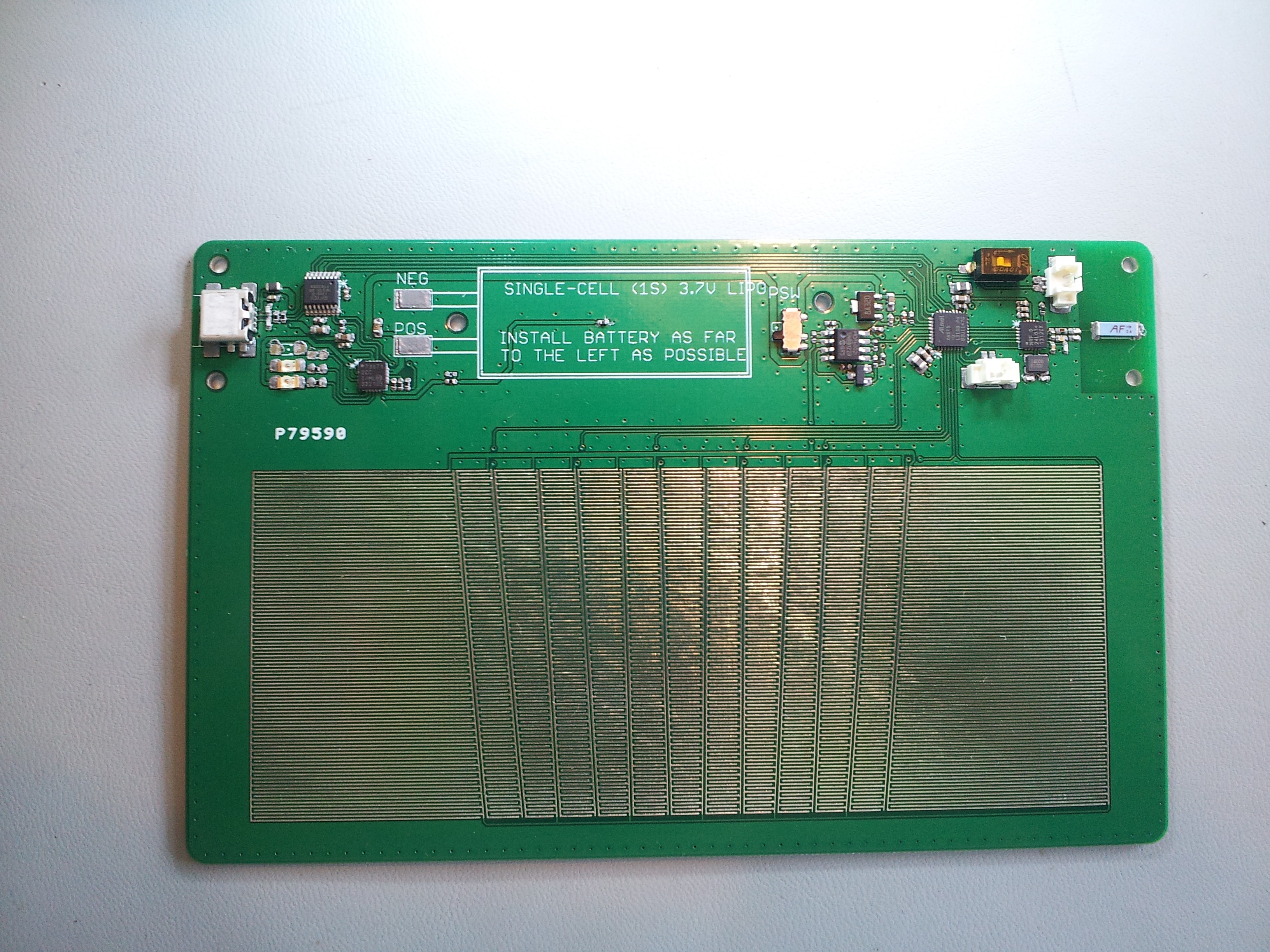
Here's the latest, Gen3 Foot Controller PCB. You can see the interlace pattern and the six "string" zones. The area between and around the string zones are linked together to form one big auxiliary FSR zone. This way, even if you aren't ready to strum the strings, the user can essentially set the dynamic level in advance. It's a feature that's not tested yet so I won't talk about it any more, but the electronics are there for when I'm ready to implement dynamics.![]()
The 3rd Gen foot controller is wireless (NRF chip on the far right), and has a rechargeable lithium-polymer battery that will last 12-14 hours. It also had indicator LEDs for charge state, low battery, and control activity. The main MCU is an ATmega, which is to the left of the Nordic RF chip.
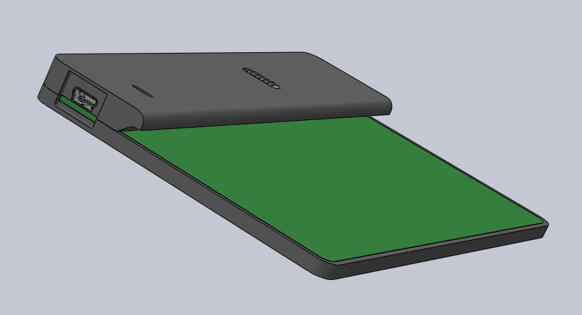
Here's the 3D model of the full assembly. The pad area actually would have the padding layer and outer contact paper layer on top, but those aren't modeled. I have a prototype, but I'm traveling at the moment and can't take a picture...
![]()
-
Production-worthy Picks
09/04/2017 at 05:32 • 0 commentsOne of the goals of the project is to take it into full production. That means picks that can be precision-replicated, and easily replaceable.
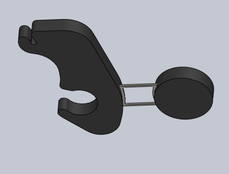
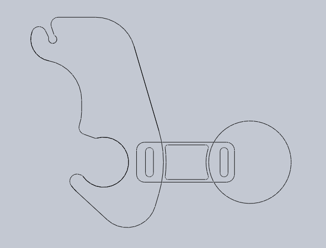
The first versions of the picks were fully captive on the pick axle, which meant you had to slide everything off of the pick bridge to replace a single pick. The latest version snaps into place on the shaft. The outline below shows the main axle snap feature (bottom left), and the control rod snap feature (top left).
![]()
I also replaced the music wire springs with custom-designed, laser-cut leaf springs. They're made of spring-tempered bronze, and will be over-molded into the production picks.
![]()
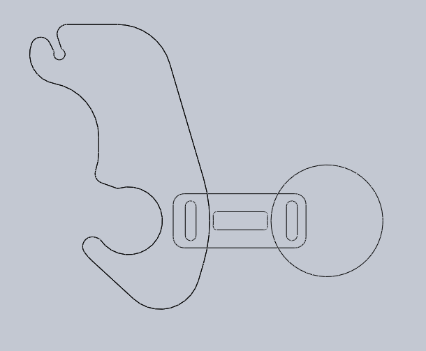
Here's a line drawing, showing how the spring is placed in the pick body:
![]()
I designed multiple variants of the leaf springs, each with different stiffnesses. Heavier gauge guitar strings get stiffer leaf springs. This way, you're low E string volume sounds the same as your high E string. The leaf below is stiffer than the one above.
![]()
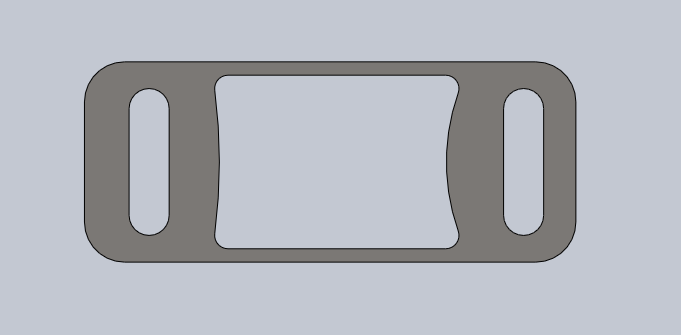
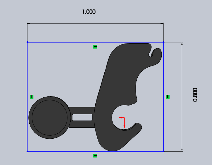
Here's the overall dimensions of a pick:
![]()
Of course, I had to try it out. I bought a desktop plastic injection molding machine from LNS technologies:
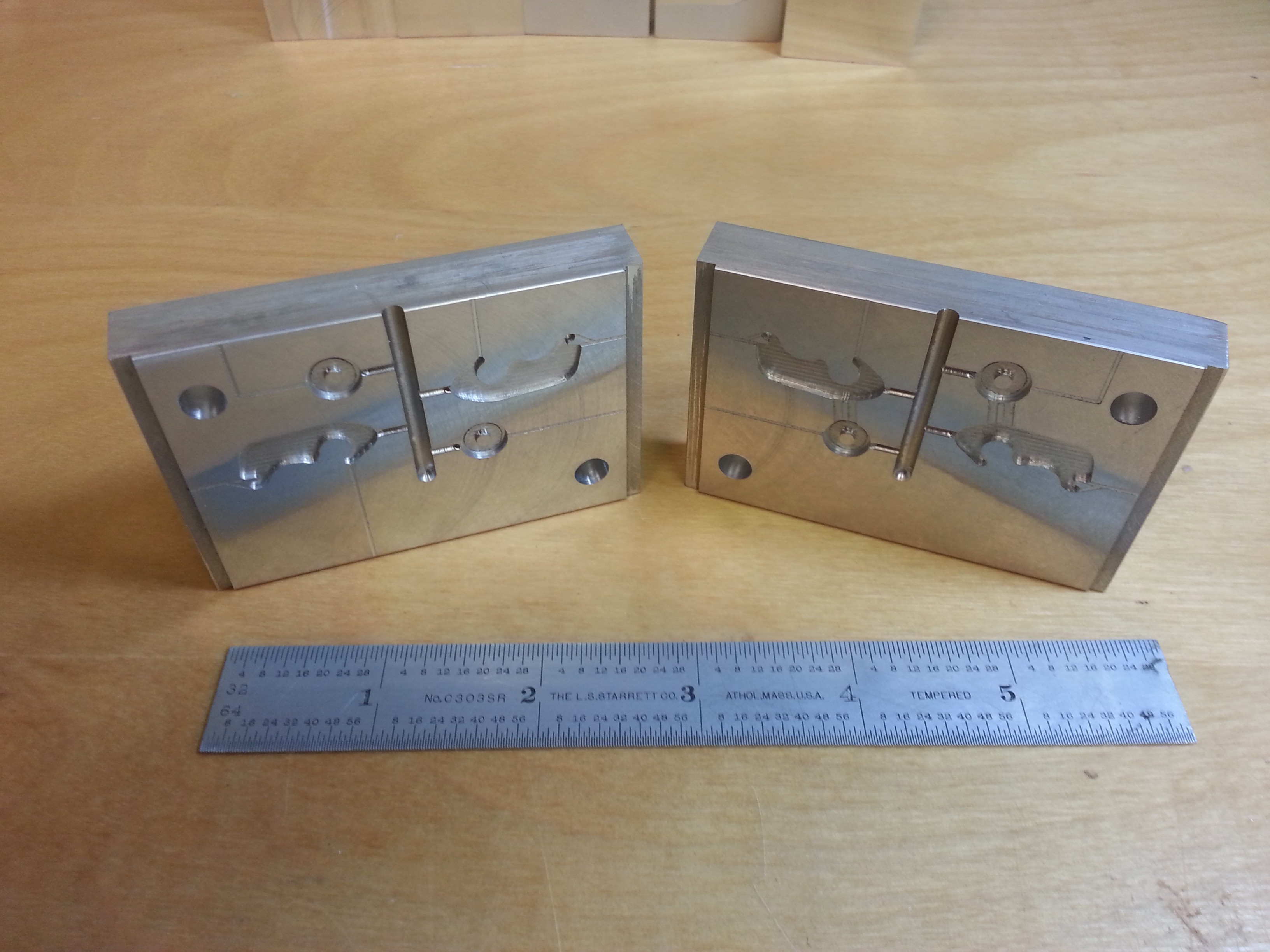
...had a mold made:
![]()
And here's the final product! These are as good as production-ready:
-
WORKING DEMO!
09/04/2017 at 05:27 • 0 commentsSo, here's a video of the first point in the Gen2 development where I get to fully demonstrate the system. I'm using an updated version of the foot controller, which is wired, and a slightly older version of the control PCB that takes wired control rather than wireless.
Nevertheless, it's the same concept, and it works!
-
The Control Board
09/04/2017 at 05:03 • 0 commentsFirst, the schematics are published in the Files section of my project page, so if you want details, go there.
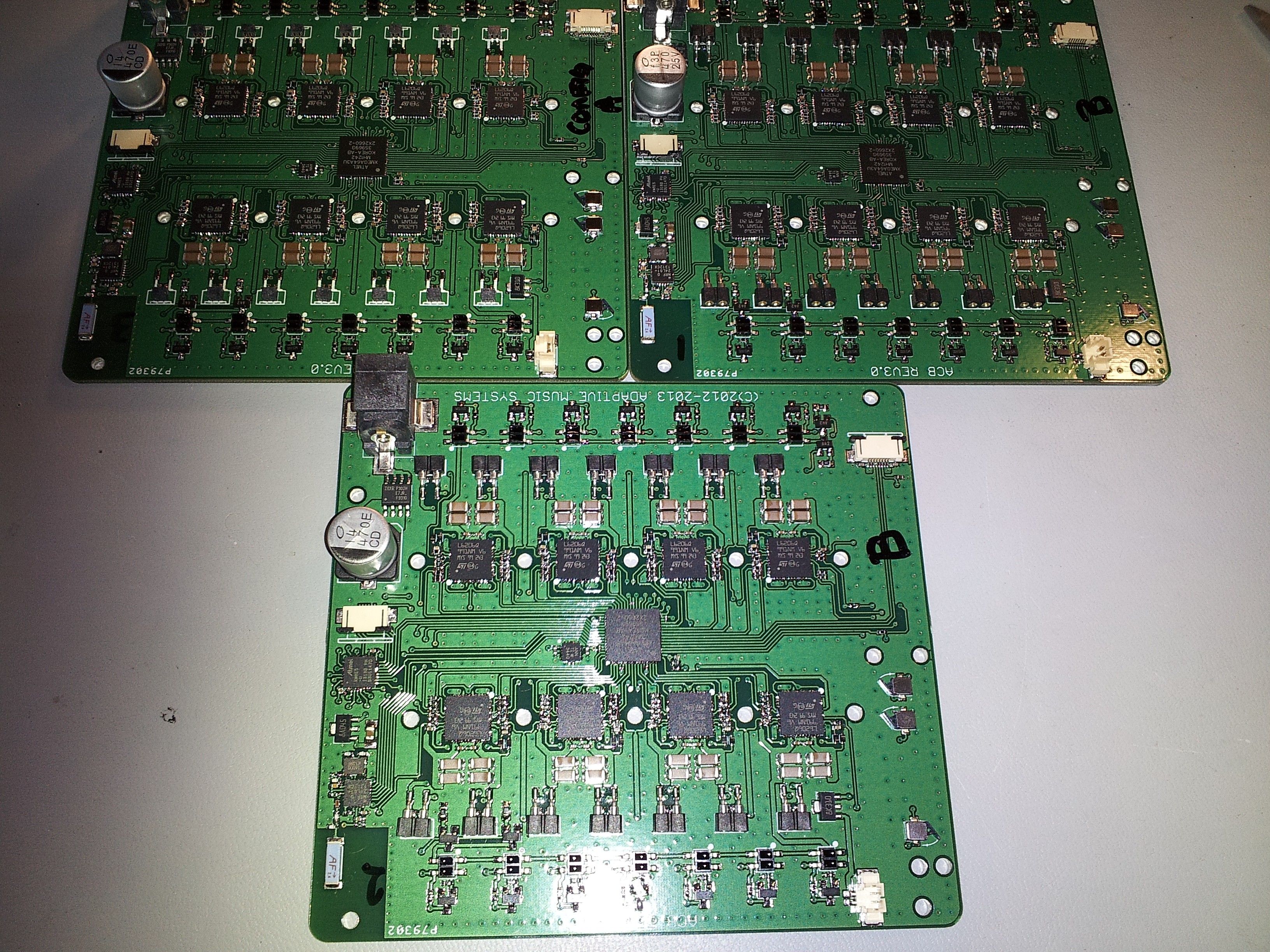
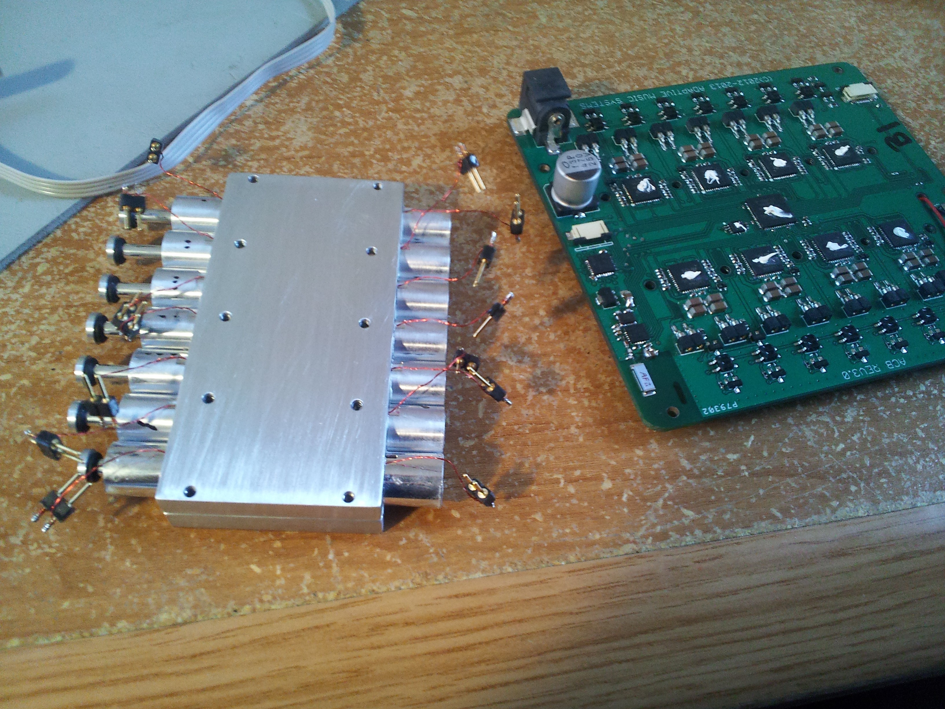
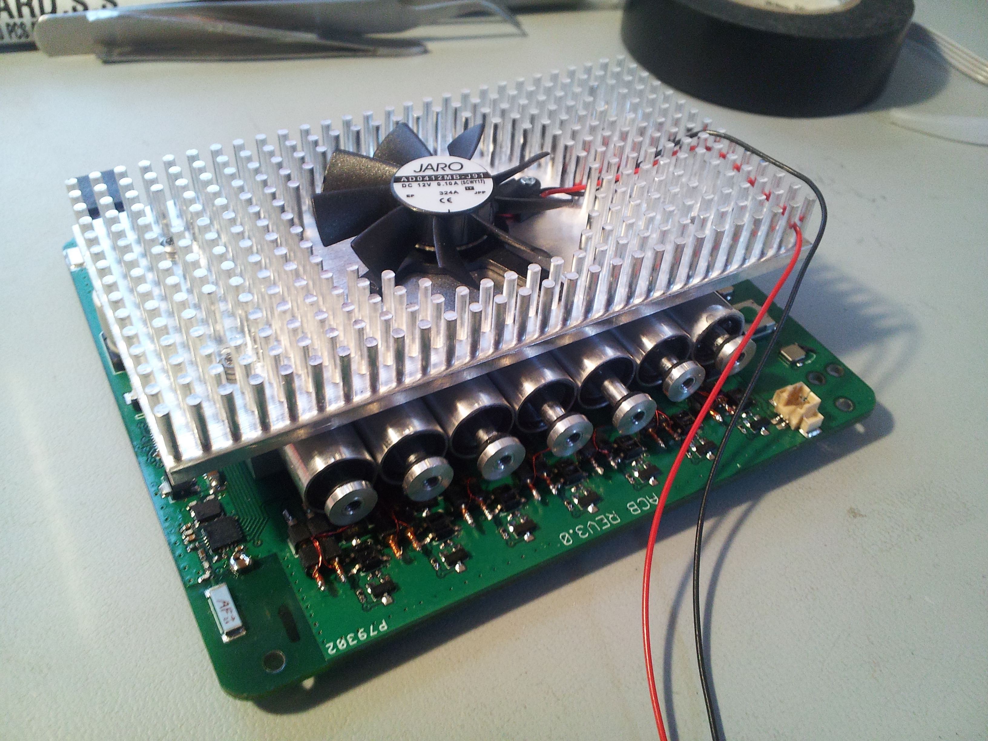
The control PCB is basically 8, dual full-bridge power controllers under control of an AVR Xmega MCU. Basically, I have 16 full-bridge circuits. I use 14 of them to control the actuators (2 per actuator x 7 actuators). I use one of the extra channels to run the heatsink fan, and the other goes to run a ball-screw linear actuator that is intended to give me dynamic control over the strumming (sorry - I'll have to get into this later, too).
![]()
Yes, I hand assembled those boards with my tweezers, a USB microscope, and an unmodified toaster oven.
The board is powered by an external battery or DC power source, and is unregulated to the h-bridges. The center chip is the main control IC, and there are 14 infrared reflection sensors along the two long edges of the boards. The reflection sensors detect the positions of the actuator plungers to close the control loop.
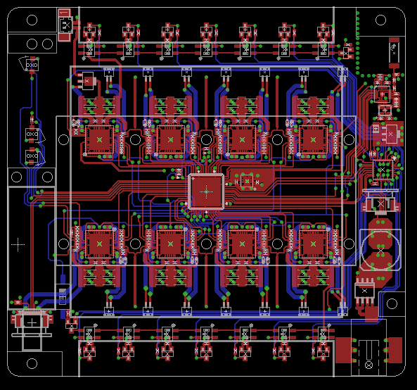
Here's the layout. It's a 4-layer board, but the power and ground layers are boring.
![]()
You may also notice at the top right is a chip antenna, which is for the Nordic NRF 2.4GHz transceiver just beneath it that gets it's commands from the latest version of the foot controller. The small IC just below that, by the FPC connector is an auxiliary MCU which runs the wireless link and relays decoded commands to the main control IC via SPI (since it's super busy otherwise).
There are a few other mystery parts on left side of the board, but they have to do with dynamics control, which isn't quite worth mentioning yet.
-
Actuator, Detailed Design
09/04/2017 at 03:08 • 0 commentsIn the last log, I determined the two basic requirements for my ideal actuator:
1) 10mm maximum width per actuator
2) Needs to apply ~6mNm of torque to the pick
The design process was lengthy, tedious, and detailed. It took me 3 weeks to arrive at an ideal design, and would probably take me two weeks that I don't have right now to write it all up. Sorry to disappoint, but I'll try to put it together in the future.
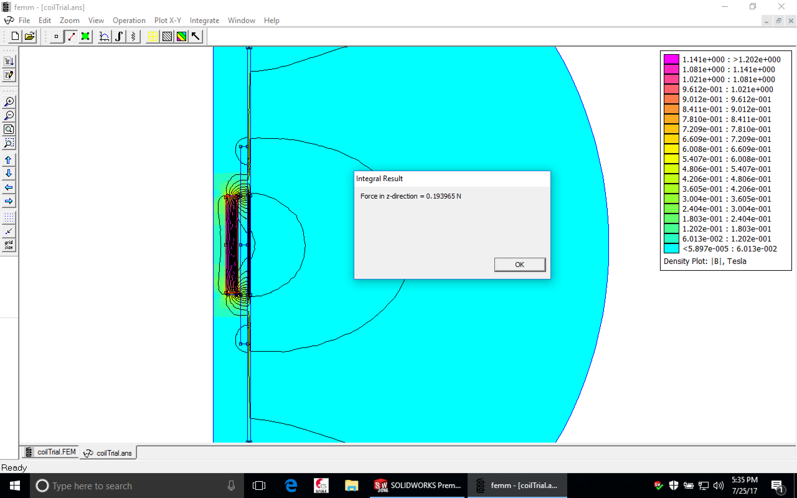
I performed my design analytics using a great free tool called FEMM (http://www.femm.info/wiki/HomePage), which performs analysis of magnetic systems. FEMM supports LUA scripting, so iterating through multiple designs was a (relative) breeze [read: took a lot of time, but it sure beats hand-calculations!]. I was able to see the force generated on the actuator along every position of my plunger magnet, as well as the fields surrounding the actuator.
![]()
First thing to do is make a prototype. I hacked together one actuator, and here's the result:
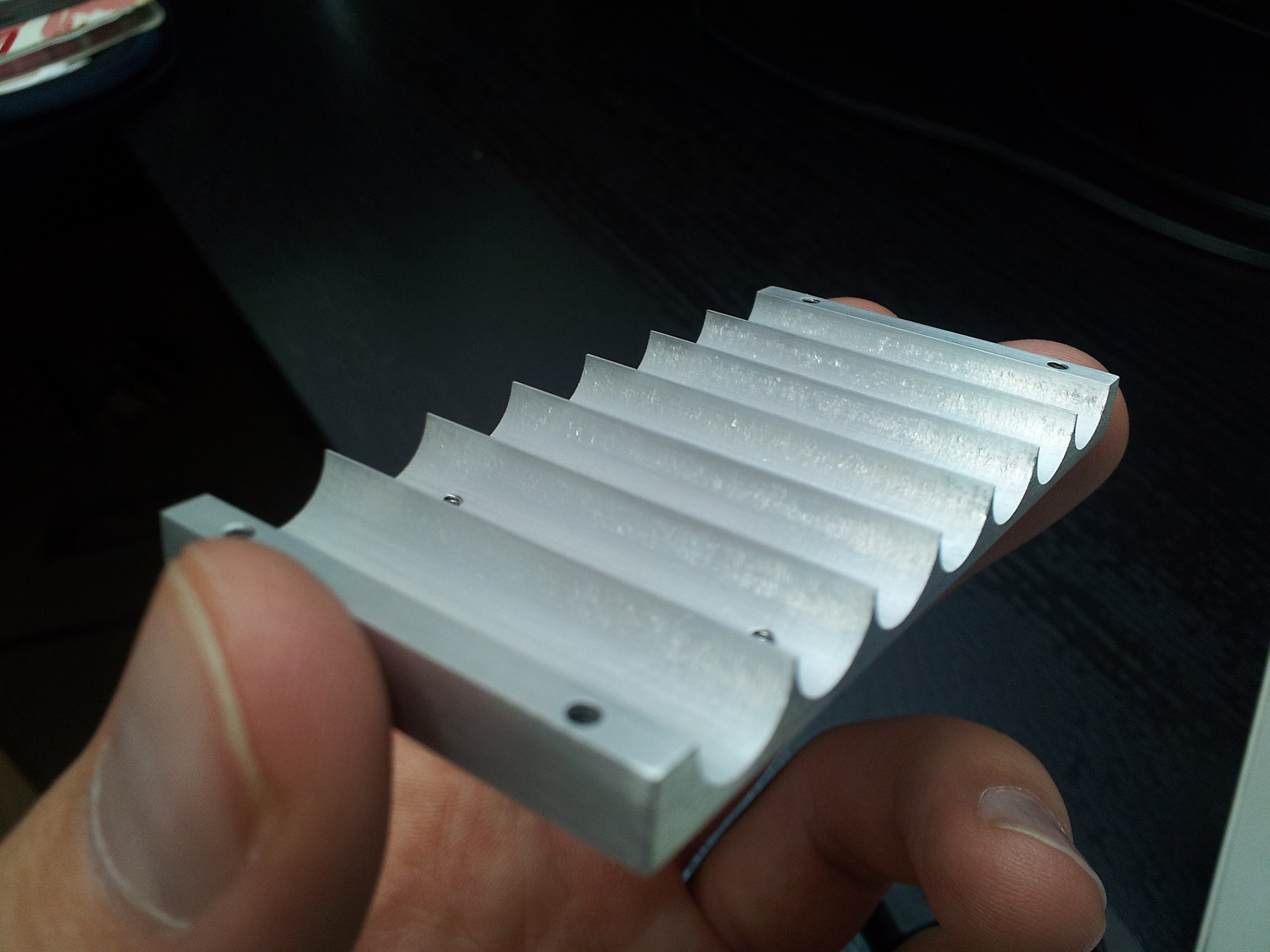
Looks good! Skipping WAY ahead:The final design starts with a two-piece (clam-shell) machined aluminum block with a channel for each actuator. Here's one half. The holes are for mounting later...
**** If you noticed there are 7 actuator slots, it's because there are 7 actuators in the design. I'll explain this later, so do your best to not let it bother you.****
![]()
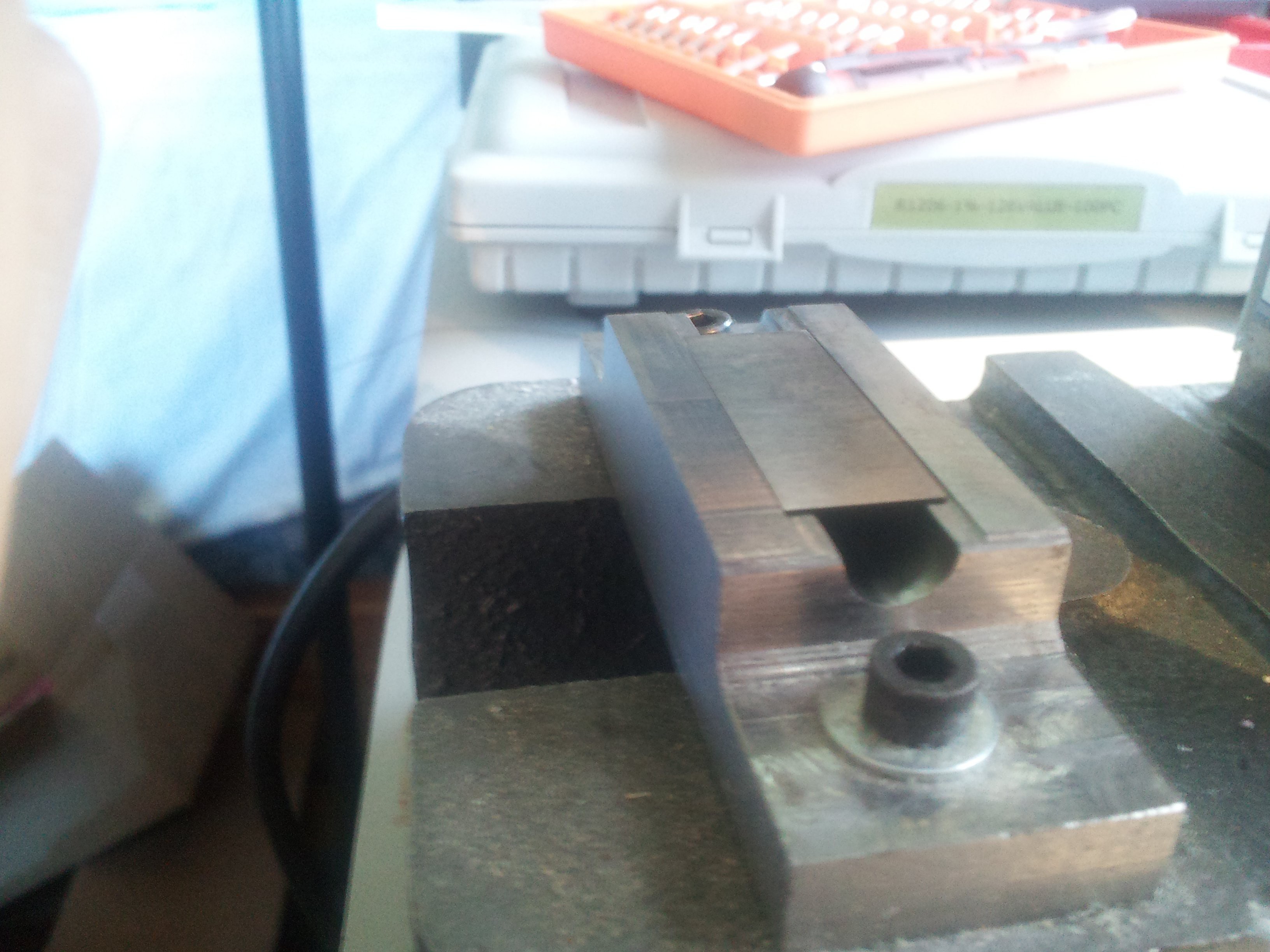
To prevent cross-interaction between plunger magnets, a 15mil layer of magnetic shielding material lines each channel. The shields were cut into rectangles with a sheer, shaped using an arbor press into a custom form and gauge pin, and then glued into place using thermally-conductive epoxy. Here's a flat piece of shield material getting ready to be pressed into shape:
![]()
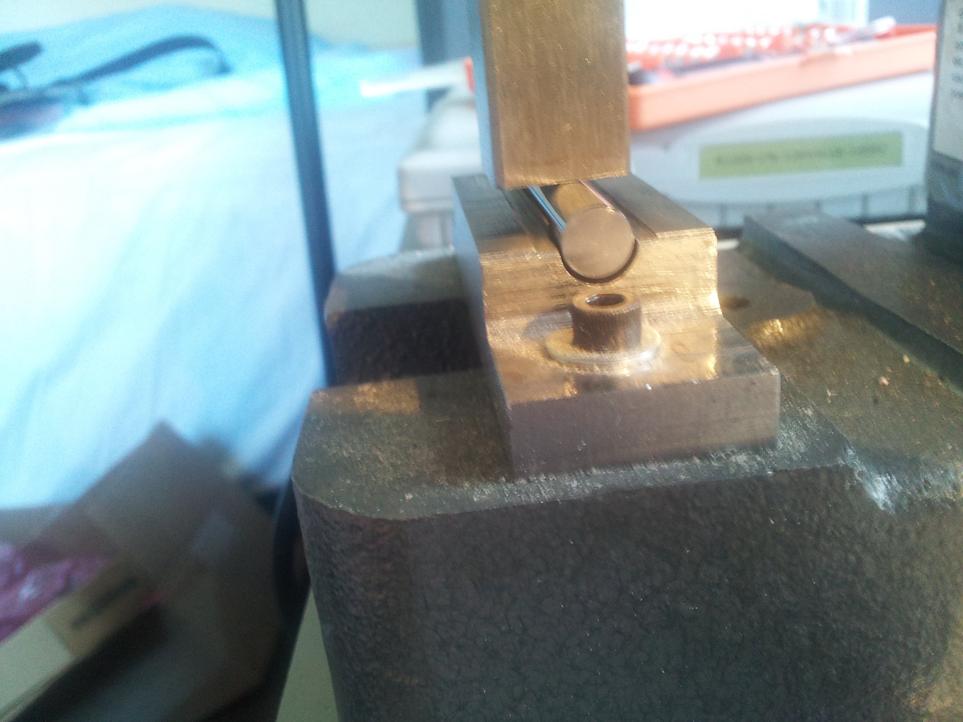
Then we press:
![]()
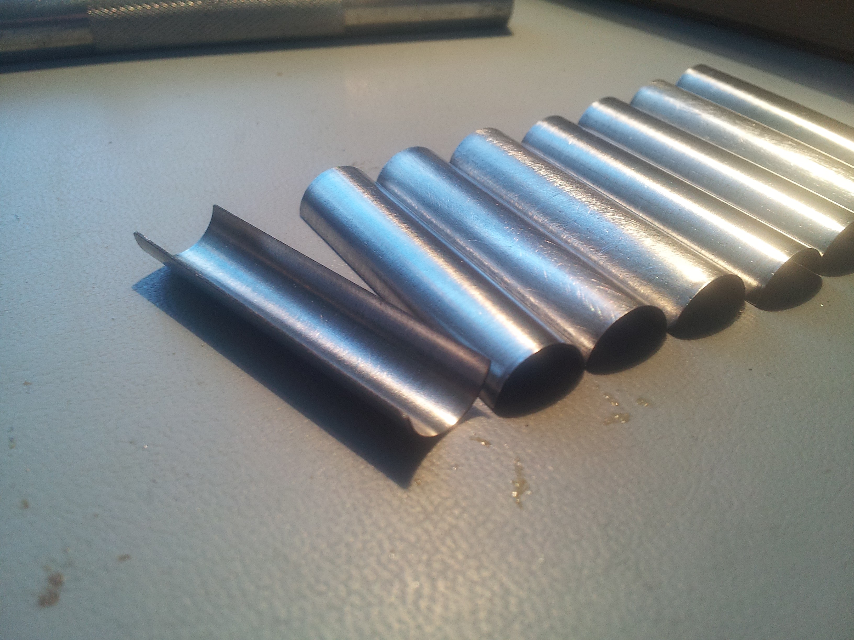
Shaped shields, ready to install:
![]()
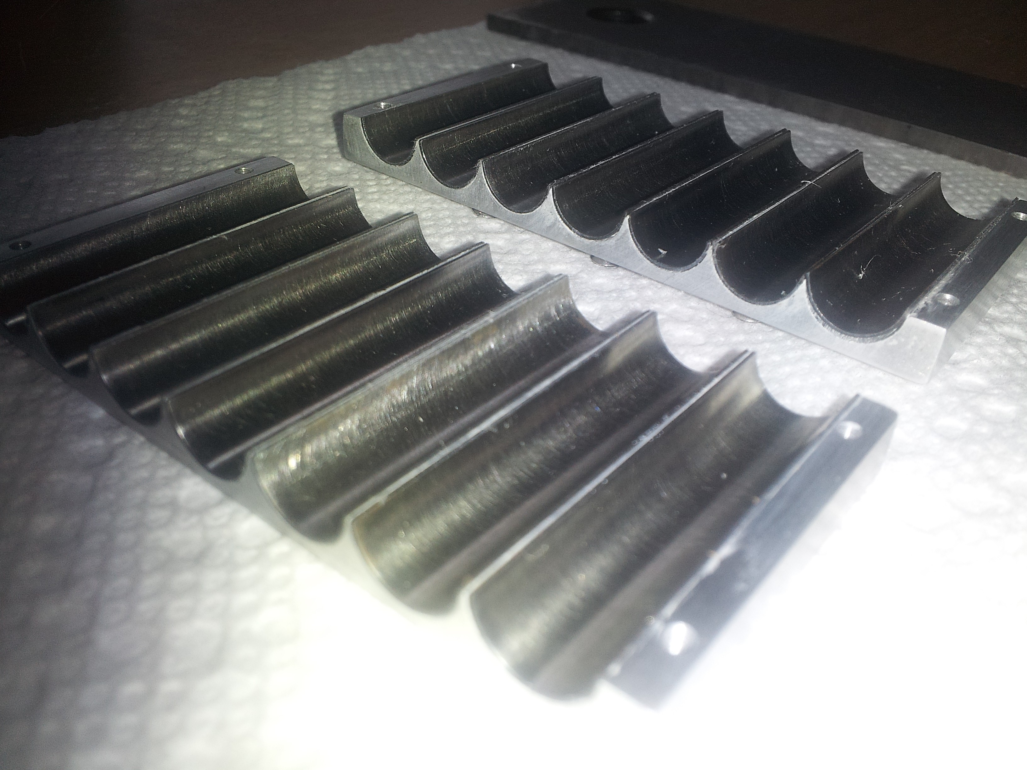
Shields placed into their channels on the two halves of the actuator block shells. A super thin layer of thermal epoxy went down first:
![]()
Gauge pins and clamps keep everything precisely in place while the epoxy cures:
![]()
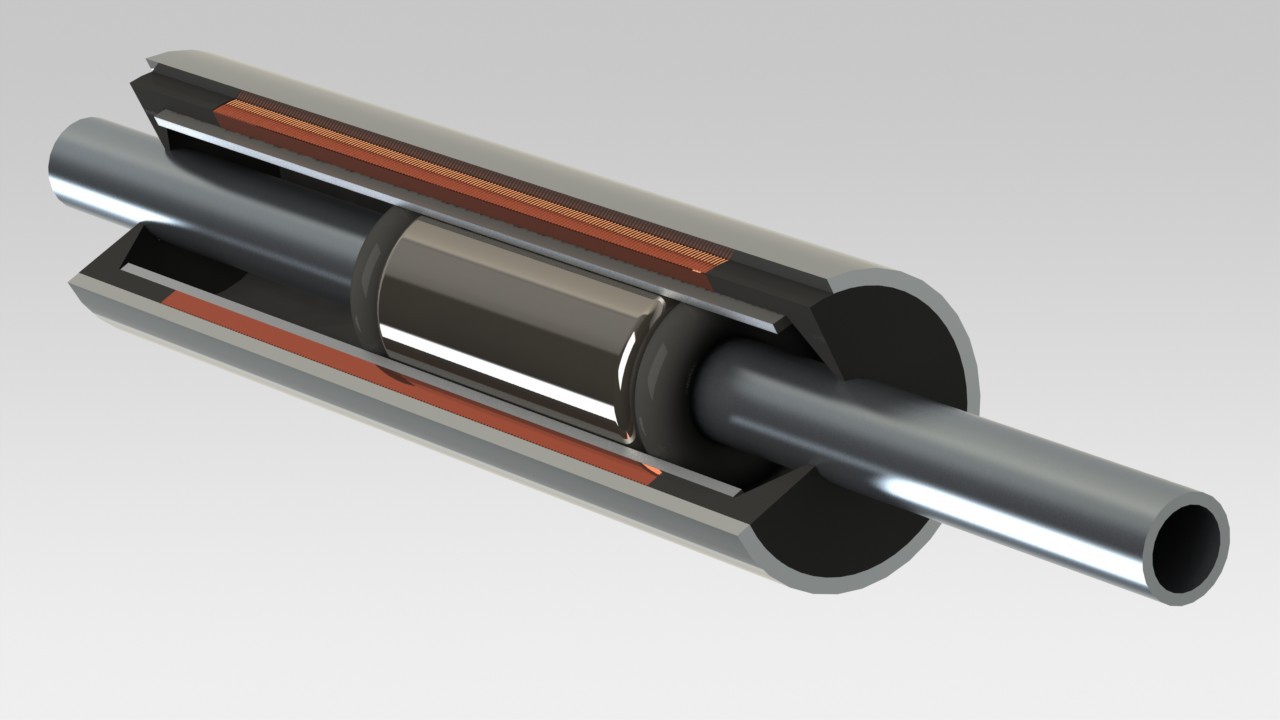
Another layer of glue, and then we place the custom ball bearing races and coils in place. The coils were made by Custom Coils, and they did a killer job. The bearing races were designed by me, and fabricated by Small Parts CNC in California. The plunger will be installed later, and will ride on rubber ball bearings that move in LINEAR channels in the bearing races. Note the wire exit channels that are milled into the bearing races:
![]()
A cutaway render showing how the bearing design works:
![]()
Another view:
![]()
The clamps come in again to make sure everything is held in place while the new epoxy sets.
![]()
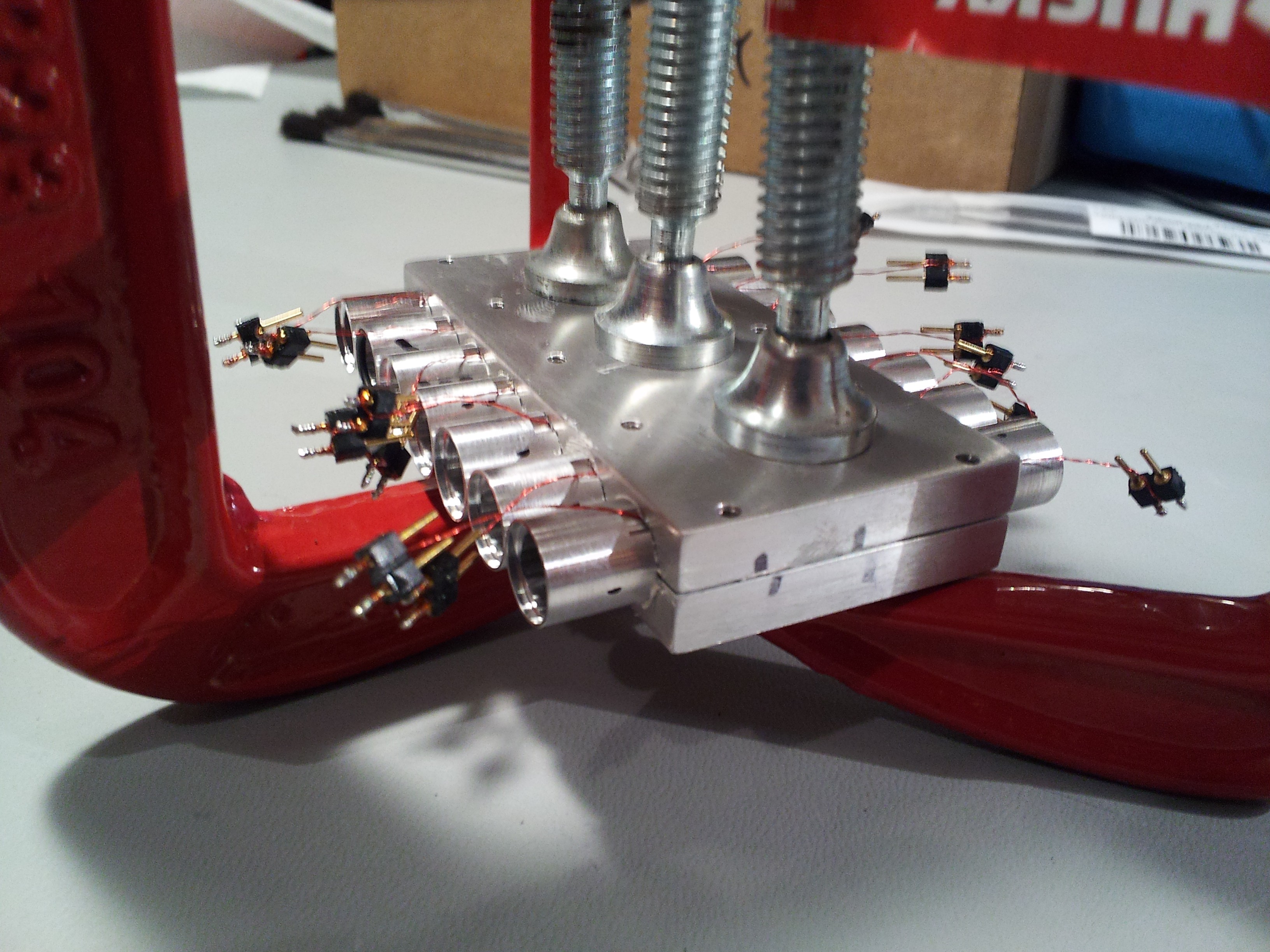
Next the plungers are inserted. The plungers are custom aluminum rods with cylindrical permanent magnets glued in place at their centers, and o-rings + press-fit caps at the ends. All custom machined to perfection. Each plunger rides on 8 rubber ball bearings inside the races.
![]()
Check out how smooth and silent the motion is!:
The actuator block gets mounted directly to the control PCB (more on that later), and acts as a heatsink for the power electronics. Thermal paste (not epoxy) goes onto the power IC's first!
![]()
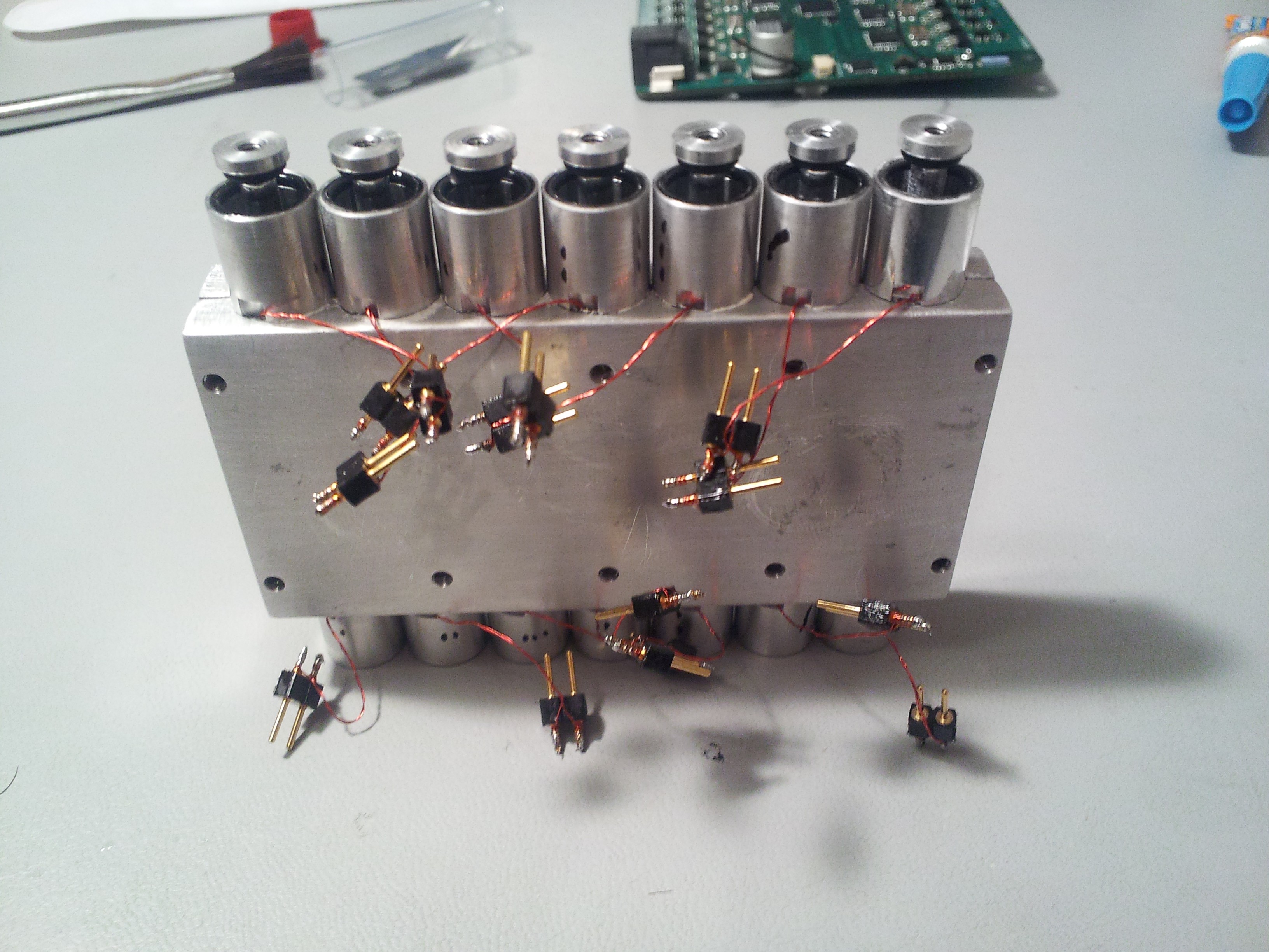
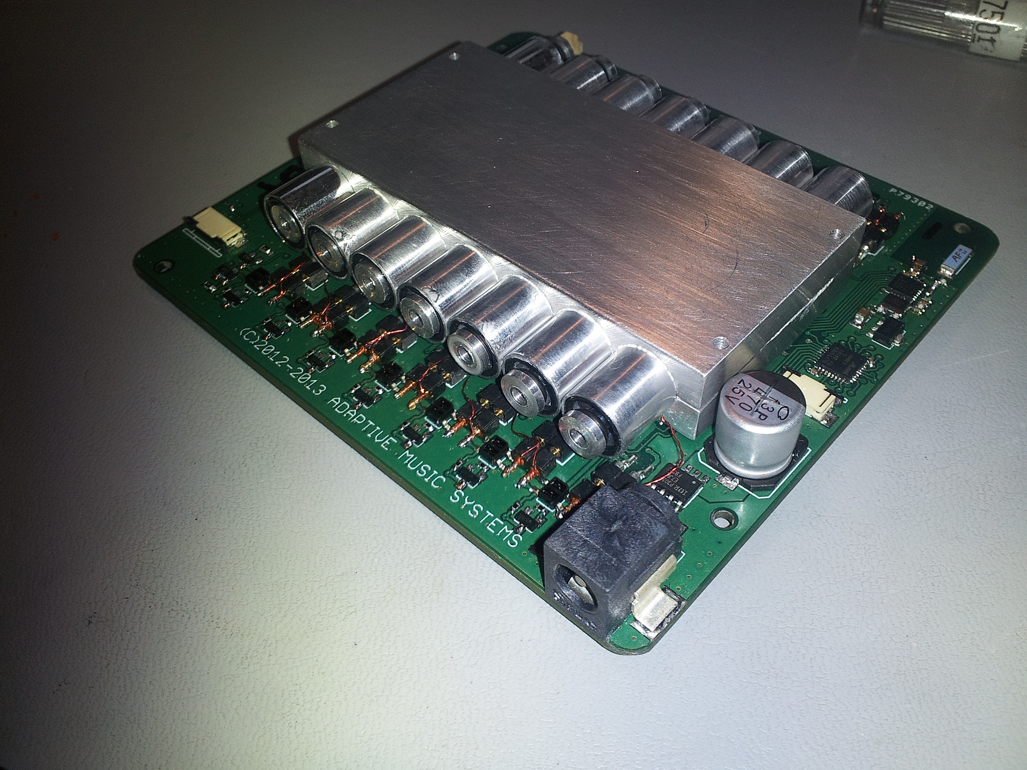
Actuator Block mounted to the control PCB, and all of the coils connected up:
![]()
A custom heatsink bolts to the aluminum block, and keeps things running cool. The fan rarely necessary, but is temperature activated and super quiet anyway.
![]()
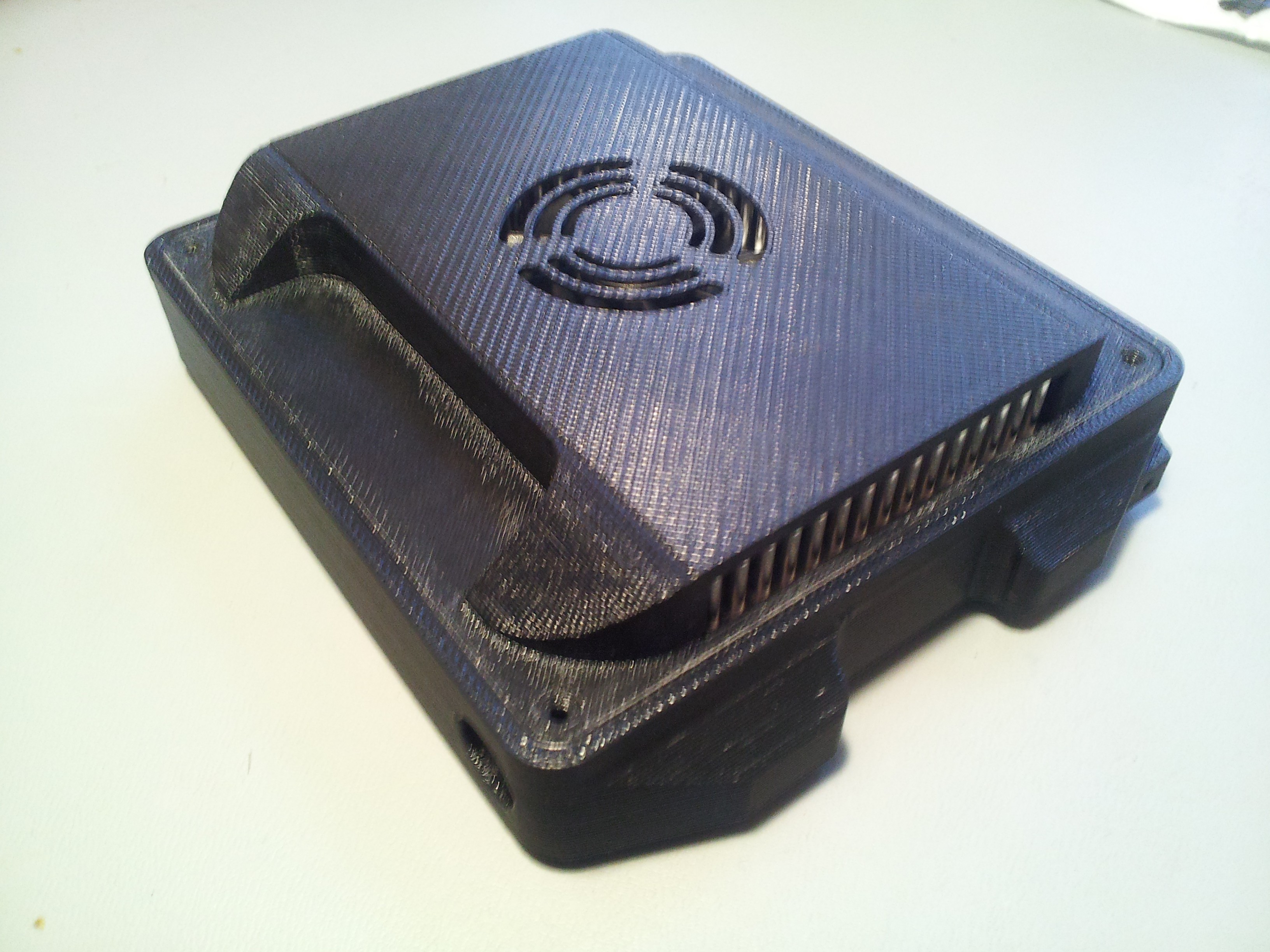
Now we throw it in the enclosure:
![]()
The whole thing weighs 10.5oz.
Here's a quick video of the system initializing / demonstrating control. There was one small glitch in the firmware that caused odd motion on one actuator, but you get the idea:
-
Actuator Requirements
09/02/2017 at 17:51 • 0 commentsSo now that I had a solid picking concept prototyped and working, the next challenge was finding suitable actuators for the job. My desire was to have each string independently actuated to allow any number of strings to be strummed at any time. This means an actuator for each string, and there were a lot of constraints that came along with that.
The ideal actuator (aim for ideal, settle for reasonable, right?):
- Fast enough to repeatedly strum the string quickly (appx 10x/sec)
- Powerful enough to overcome the force required to strum the string
- Quiet enough to not be obtrusive to the music
- Small and lightweight as possible
First, we need to figure out what kind of forces I need to generate. Since I was dealing with a pick with rotational motion, it makes sense to spec that out in units of torque. I wish I had taken a picture for this to show you, but I didn't. What I did was place the Pick Bridge in place on the guitar, which was laying down flat on a table. I connected a string to my pick, and routed the string over the edge of the table via a small pulley wheel. I then hung weights to the string until the pick was able to pick the string.
The result was 62g, and the attachment to the pick arm was about 10mm from the axis of rotation. This means I needed ~600mN * 10mm = 6 mNm of torque (or the linear equivalent).
There were basically two options: rotary, or linear actuators. Rotary solutions were either too noisy or large, and the linear options were either too slow, too large, or had too short of a throw. I considered pneumatics, but that concept carried a requirement for a compressor....no go.
I considered bringing the actuators off of the guitar, but that meant having some sort of linkage or cable system going to the guitar, which would be likely unwieldy and require oversized actuators to overcome the additional friction forces. Call me an idealist.
So I did what any typical hacker would do, and figured I'd try my hand at designing my own linear actuator- how hard can a few magnets and coils really be?
Rotary actuators were scary to me at the time, so the concept is a permanent magnet linear solenoid. It had to be bi-directional, and there's only two ways to get bi-direction motion out of a linear solenoid actuator:
- With a spring, like the setup of a typical solenoid actuator, where the electromagnet provides the push, and the spring does the pull (or visa versa), or
- With two coils, one for push, one for pull
Since I planned to strum the string with EACH motion (forward and backward), a spring'd solution would require constant power to hold the plunger in one of the positions if the pick wasn't moving. Battery life and heat considerations quickly directed me at the dual-coil configuration.
The cut-section render below shows the first concept design. It looks like there's just a single coil, but it's two, side by side.
![]()
One of my ideal design constraints was that the center to center spacing between them be the same or close enough to the spacing of the strings so that I could position each actuator in line with its corresponding pick. Measurements and research into guitar string spacing led me to an ideal spacing (/actuator diameter) of 10mm.
I had my design criteria...time to design!
-
Gen2 Pick Concept, Prototype, & Test
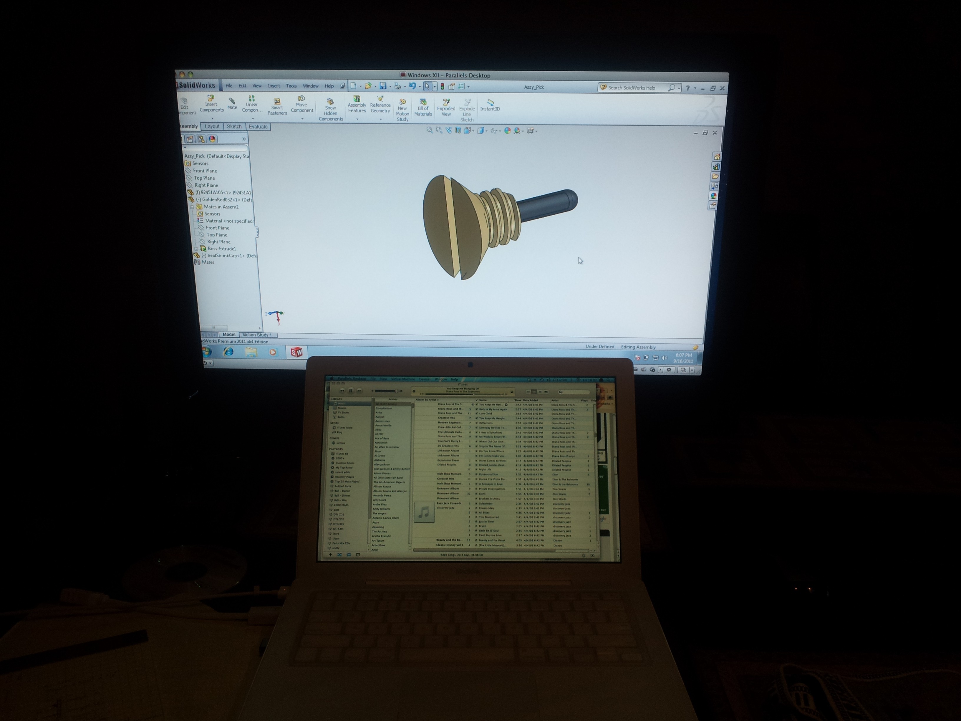
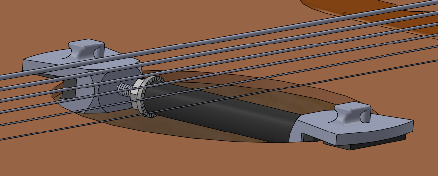
09/02/2017 at 16:36 • 0 commentsAfter seeing the shortcomings of the Gen1 design, I decided to hit the drawing board again. The main thing I realized was that the picking action cannot come from above the string, due to the fact that the string heights change as they are fretted. The only other option is to hit the string from the side if I wanted a consistent sound. This presented a new challenge, since the picks were going to need to be designed to fit between the strings. I sat in my sister's apartment in California late one night, and came up with this concept for the pick:
![]()
The concept was a flexible piece of wire with a rubber coating on the end, fixed into the end of a vented screw. Vented screws have a hollow body to allow fluids / air through, but also happened to work nicely for holding a small piece of music wire (spring steel). Here's an animation of the new concept, which shows the pick bodies I designed, as well as the Pick Retainers that would align and hold the picks on a shaft over the strings.
The idea was to put linear / solenoid actuators somewhere behind the new pick bridge, and use push/pull cables similar to those used in model aircraft to rotate the new picks forward/backward between the strings.
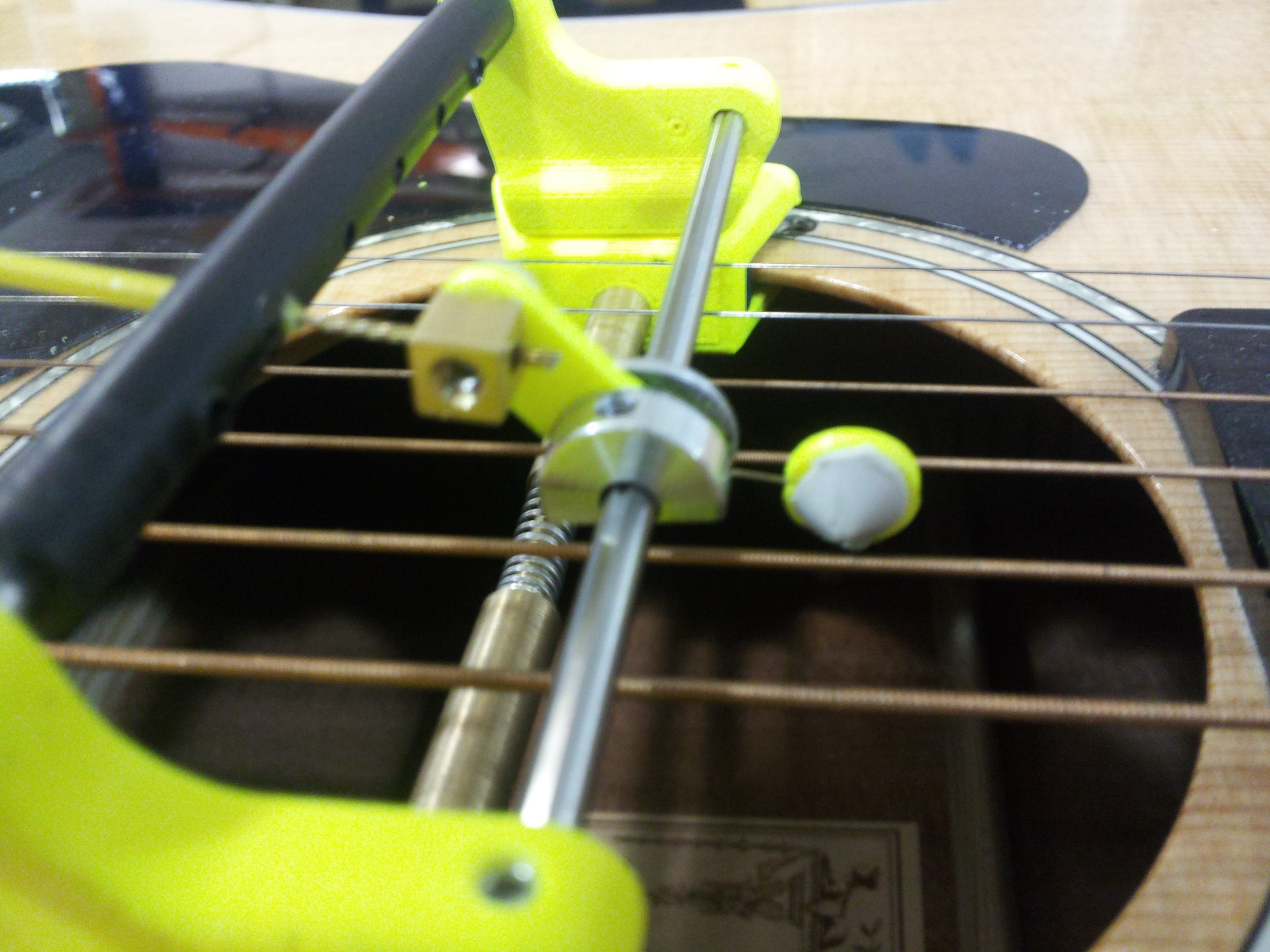
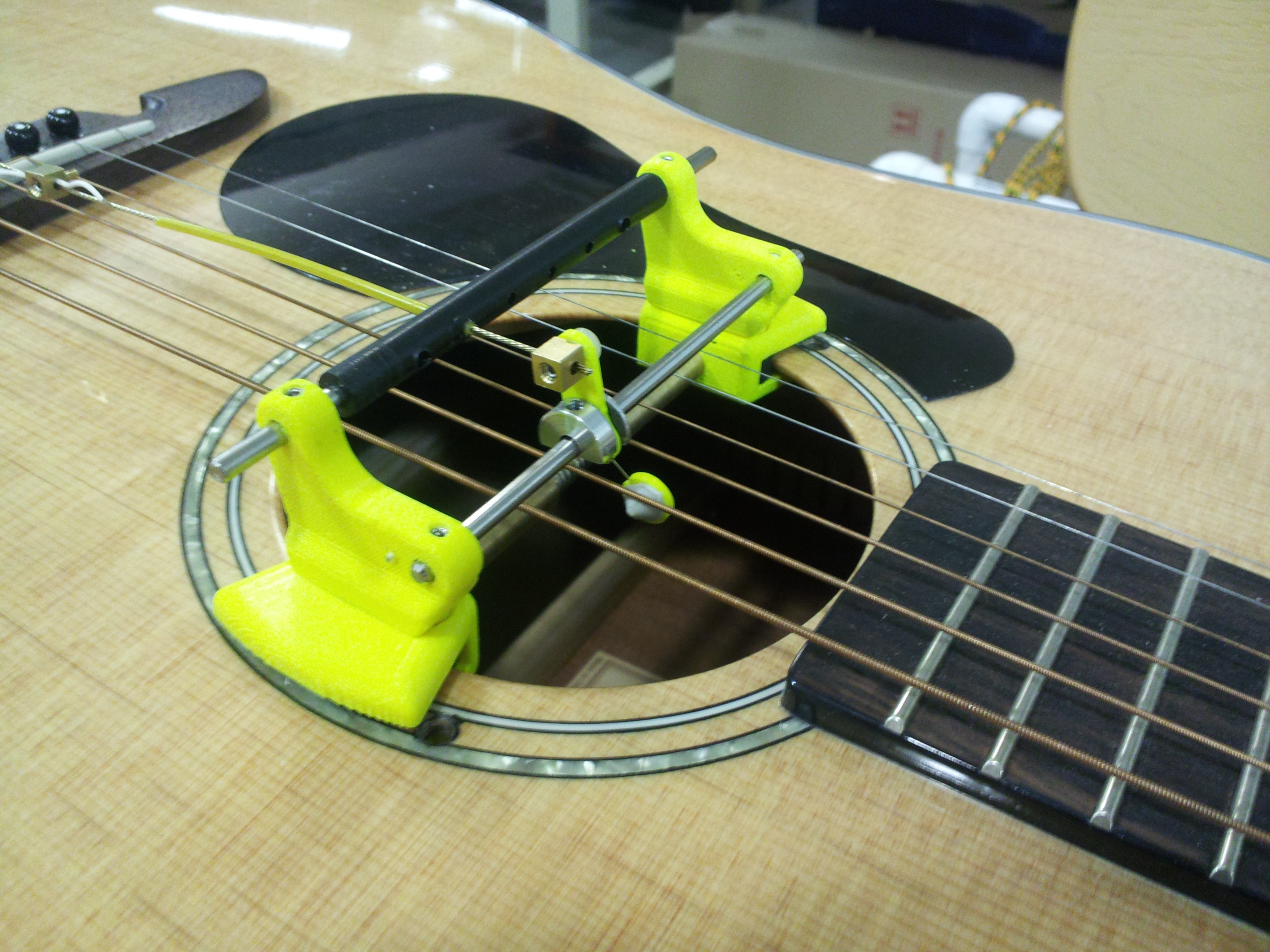
I also came up with a new mounting system, designed to be non-intrusive. It was basically a telescoping rod with a spring that would hold 3D-printed mount bases to the walls of the sound hole, which provide mounting features to hold the new Pick Bridge in place. The photo below shows an early iteration. Eventually I got smart, and made the mount magnetic - but I don't have a great picture of just that.
![]()
I also very quickly iterated the pick design through multiple prototypes / trials. The original picks were too rigid, and were SUPER sensitive to their proximity to the string; I either got full volume, or hardly sound. So I switched to rubber cones whittled out of pencil erasers to pick the strings, and put some spring steel (music wire) between the main pick body and the pick heads to give some spring to the action. Here's one of the prototype picks, showing the small spring steel wire that held the two pieces of the pick together. The pick body and head had recesses cut in to receive the spring steel, which I cut and formed myself before epoxying in place.
![]()
And here is the prototype in action. GREAT sound, and I'm super happy with it. The addition of the spring steel to the pick body design really brought the concept together. All of the plastic parts were 3D printed. I also demonstrate the new magnetic mounting system, which I'm super proud of. It really satisfies the need for this thing to be able to be used by someone with only one hand.
![]()
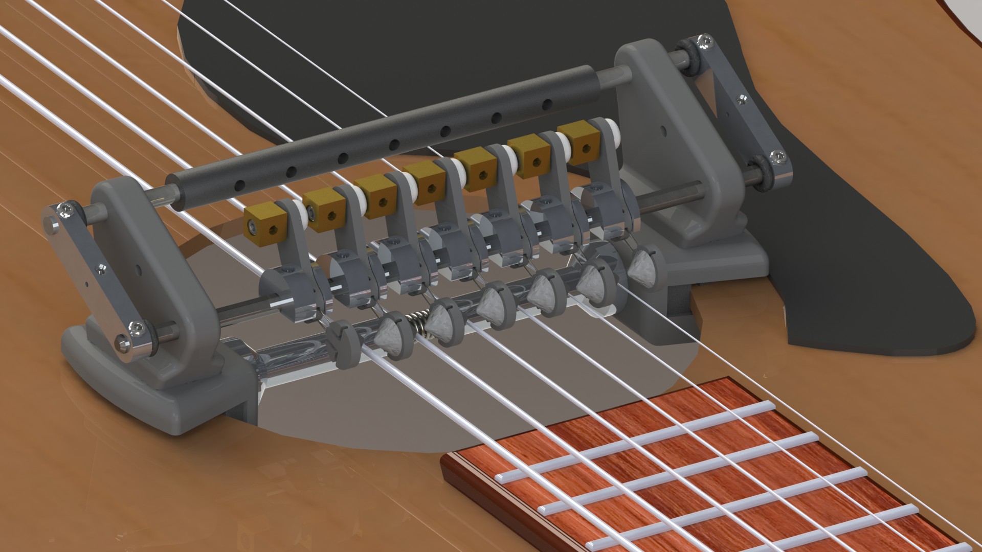
Adding the spring steel to the design also helped because I found that the larger strings needed more gusto than the smaller strings to affect the same sound. Since music wire comes in a TON of different sizes, I was able to dial in the exact amount of pick stiffness required for each string to get a nice consistent sound. The next iteration also added a second spring steel piece to help keep the pick head from pivoting. Here's a render:
![]()
-
Final Touches on Gen1
09/01/2017 at 17:55 • 0 commentsAfter landing on a successful iteration of the Picks and Pick Bridge assembly, it was time to construct the rest of the system; specifically, the part of the system I call the Motor Module.
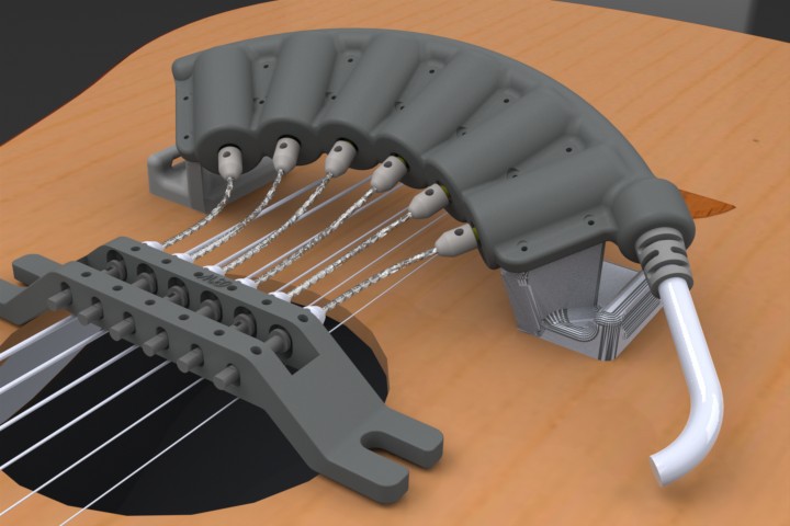
In case you didn't see my first log entry, the concept for Gen1 was to use motors to rotate picks that are held in place over the strings at the sound hole. Here's an early render (which you may have already seen):
![]()
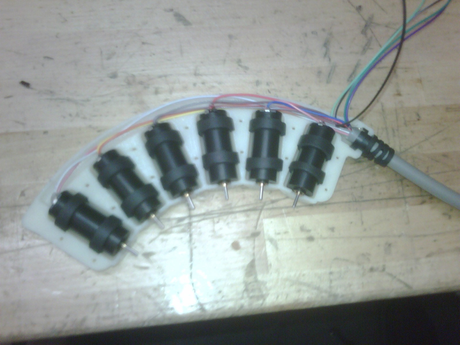
So now, I'll show you the innards of the Motor Module. The construction is pretty simple: A two-part housing, containing six brushed DC motors. Here's the Motor Module with the top half of the housing removed). The DC motors are from MicroMo, which were just set in place with some rubber isolation rings. The channel along the top was where I routed the motor power wires, which exited on the right side through a strain relief. As you can see, It's actually pretty small. The arc was diligently engineered so that the flexible shafts I used to drive the picks would fall into a natural bend.
![]()
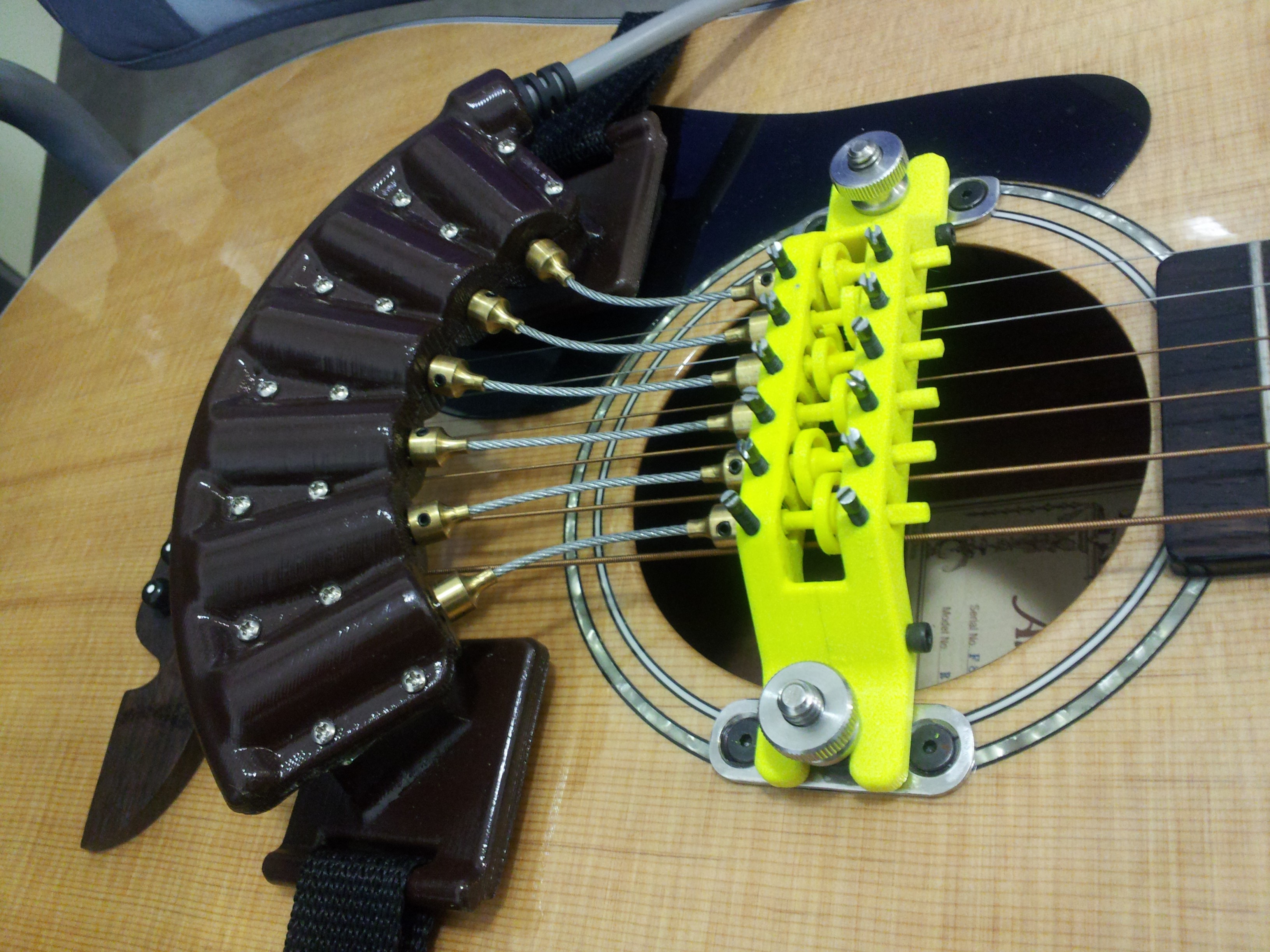
.....AAAAAND.....here's the Gen1 system all together!
![]()
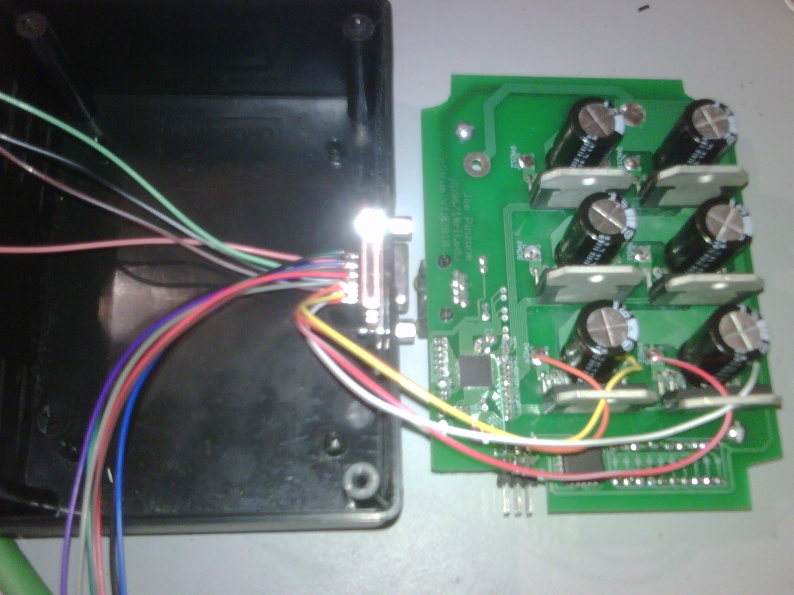
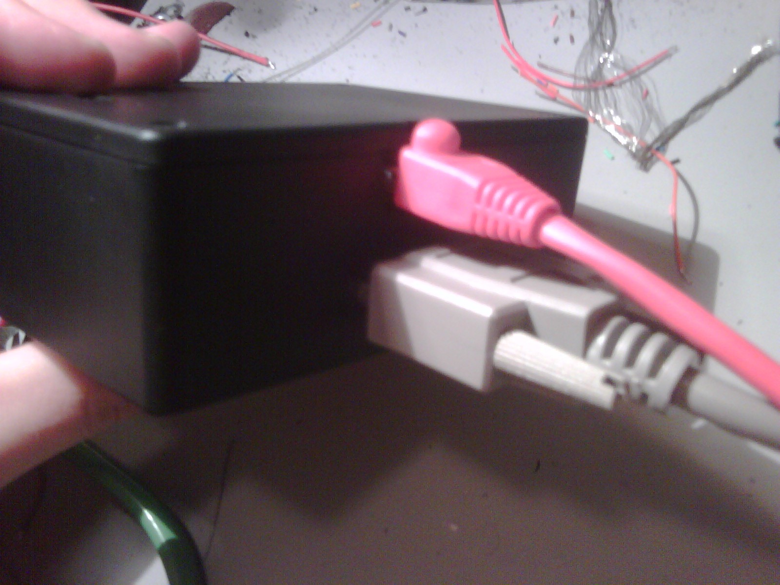
Now, what you haven't seen so far is the motor control box. The control box housed a custom PCB with an AVR MCU and six half-bridge motor drivers. The MCU took the analog inputs from the foot controller FSRs, and would control the half-bridges to rotate the motors/picks. This version used 12VDC power from a wall wart. A repurposed VGA connector was used to connect to the Motor Module, and an RJ45 connector (with blinky lights) was used to connect the foot pad.
A belt clip on the control box mounted nicely to the guitar strap while in use.
![]()
![]() Here's a quick video demo of the first tests of the foot pad + controller box:
Here's a quick video demo of the first tests of the foot pad + controller box:Unfortunately, I don't have video of this version of the system running, but it worked GREAT! It it had issues that eventually caused my friend to abandon it, though. The key issues were:
1) No encoders on the motors, so I was using time-based actuation (bad choice in retrospect). The picks naturally ended up wanting to stop touching the strings after their initial rotation, which caused an undesirable buzzing noise. Unintentional double-strumming was also an issue.
2) The flex shafts were too stiff and not balanced. the whole thing wanted to shake every time a motor spun as a result. Friction comes in many forms.
3) The picks were difficult to adjust to get the sound to be consistent. That's because as you fret a string, it gets pressed down and moves away from the pick bridge. This causes decreased strum intensity for strings that are fretted further down the fret board, and is really detrimental to making good music. After about 5-6 frets, the picks can't even contact the string.
4) She couldn't adjust or replace the pics herself without a lot of hassle, and this project was supposed to be liberating, not add more dependency on others.
Of course, I can't just abandon the project. On to Gen 2!
Adaptive Guitar
An electro-mechanical system designed to allow a disabled musician to play the guitar with one hand (and a foot).
 Here's a quick video demo of the first tests of the foot pad + controller box: