-
Update Summer 2018
08/01/2018 at 00:46 • 0 commentsI've updated it a lot. Getting it ready for the 4H County Fair. They have a decorating contest :D I've added a foot pedal so that small kids can step on it and trigger it. Last year I tried sonic ranger finder, major fail. Worked fine at home, indoors, outside anything and everything would trigger it. I added much louder speakers, and a new 7.5v regular that runs of 12v from battery (one of my design criteria is that everything run off the 12v battery, makes it portable, don't need to have power close by). Also totally reworked the lid lifting mechanism, the original worked about ~50% of the time, finally had a change the program so that the lid was open all the time. Now I use a CAM and its smooth and 100% reliable. I have uploaded video's of each of the mods through out the winter. I am very happy with the CAM solution, 100% reliable, simple, uses 3D printed parts.
I will upload new video, of the toilet working with all the updates. I need to do this final test before it's 8 day run.
-
Halloween, Ceramic glue problems
11/08/2017 at 18:11 • 0 commentsThe Captain Underpants Toilet was out for Halloween. It was a big hit with everyone who showed up. Took some explaining for the adults the kids all got it.
I added a LED light in the Bowl. I put some red shading on it so it glows red. I control the LED from the Arduino. This looks really good at night.
The new Cam system worked well. The current problem is the glue that holds the Cam follower (3D printed) to the side of the tank, keeps coming off. I got a new special professional hot glue gun with hot glue that has much higher temp. That has not solved the problem. Everything will be fine then one day the Cam follower part will be laying inside the tank not glued to the side. This is a major pain as the alignment for this part is very difficult. I'm not looking into some type of Ceramic epoxy.
-
Updates after the Fair, new Tank Lid Mechanism
09/19/2017 at 14:43 • 0 commentsUpdate after the Fair. The Fair was 9 days at least 10 hours a day. The Captain Underpants toilet ran for the entire fair. Some parts worked a lot better than other parts. The toilet bowl lid worked fantastic, it was rock solid. The Eyes worked very well, had a problem with the hot glue I mounted them with. The toilet was outside and it got very hot, the hot glue did not hold the entire time. I had to reattach the eyes at least twice. Their where two main problems, the worst was the tank lid mechanism, it basically did not work. After the first day I turned off the Tank Lid and had it in the open position so you could see the eyes.
I also had problems with the speakers. The speakers ran off 4 AAA batteries and they would only last for use under 2 hours. Around the third day I converted the speakers to run off the 5v system. It was very hard to work on anything at the fair, the heat and trying to solder anything. While this solution worked it still had issues, lot of distortion ( was meant to run off 6v not 5v) and the regulator would over heat.
I have totally redesigned the tank lid mechanism to use a CAM. I will upload all the stl files, I 3D printed all the parts. There where several versions as I tweaked the design. I'm including a video where you can see the design and how smooth the movement is now. I'm very happy with this design it will be reliable.
I'm going to upgrade the Eyes to RGB Leds. Also I'm going to drive the sound arduino off a new switch that I added instead of controlling it from the master arduino. The motors produce a lot of noise, and I have intermittent problems with the sound not being kicked off.
I'm going to put it out for halloween with all the updates and enhancements. I will upload video from that. Looking forward to being able to have the Eyes change from Green to Red then Purple.
-
Going live for 8 days
08/11/2017 at 22:28 • 0 commentsThe toilet will be on display for 8 days, outside under a tent. I'm not satisfied with the lift mechanism for the Tank lid. It is not reliable, very touchy. I'm going to change that to a CAM, machine it out of aluminum. That will limit the lift arm to a straight up and down motion. I will have to pull everything out and reposition the wiper motor. The bowl lid mechanism is rock solid.
-
Bringing it all together
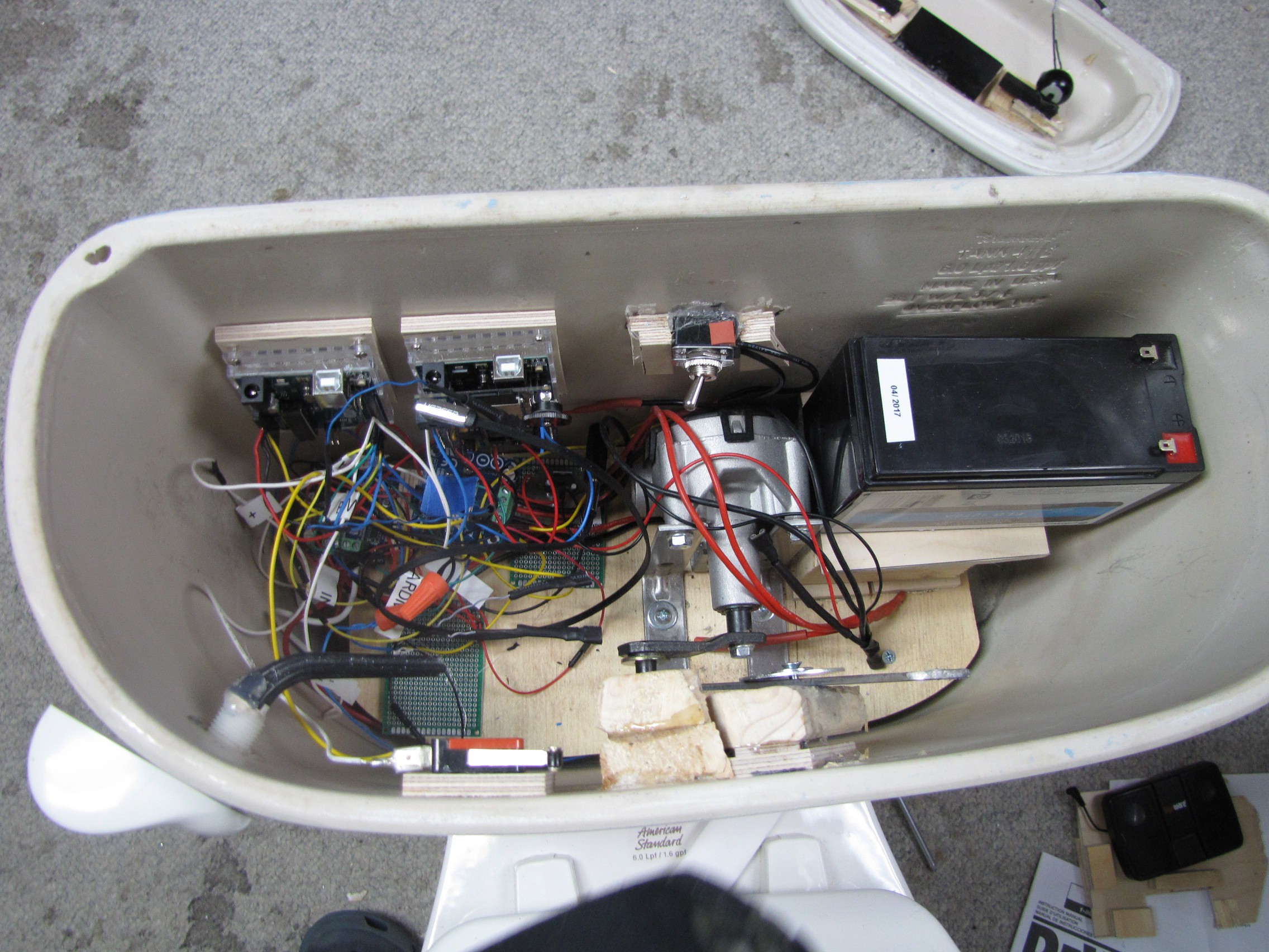
08/06/2017 at 17:56 • 0 commentsI hot glued the 12v to 5v and my Ground and 5v rail board to the bottom motor mount board. I screwed in the motor controllers to some spare wood I glued to the bottom. There are only 6 wires that need to be dealt with if I need to remove the motor mount board. Two wires go to the motor, these just unscrew from the motor controller, the other 4 wires are from the microswitches. I used #18 gauge wire connectors, these are easy to put on and take off. The biggest problem with removing the motors is I have the on/off switch hot glued to the toilet. It comes of with careful use of a flathead screw driver. I used stranded wire for the 12v wiring harness, this is flexible and easy to deal with.
I have major problems with not being able to trigger the Arduino Wave Shield from the master Arduino. In the end the problem was noise coming from the motors, the solution was to have a dedicated ground between the two arduino's and 5v.
Here are two video's of the Toilet in actions. The first is the full routine (multiple openings of the Lid), the second video the Lid only opens once and stays open for the entire routine then closes. This is going to sit under a tent during the Fair and that runs for 8 days. I will be close by most of the time. I've run it through two 3 hour test cycles, running every 4 min. There where not any problems but there where a couple of close calls, the lid arm bracket can catch on the Lid, this has the possibility of moving it so that it does not close and then could knock it off.
Full Routine
Limited Routine
-
Electronics on bench/testing
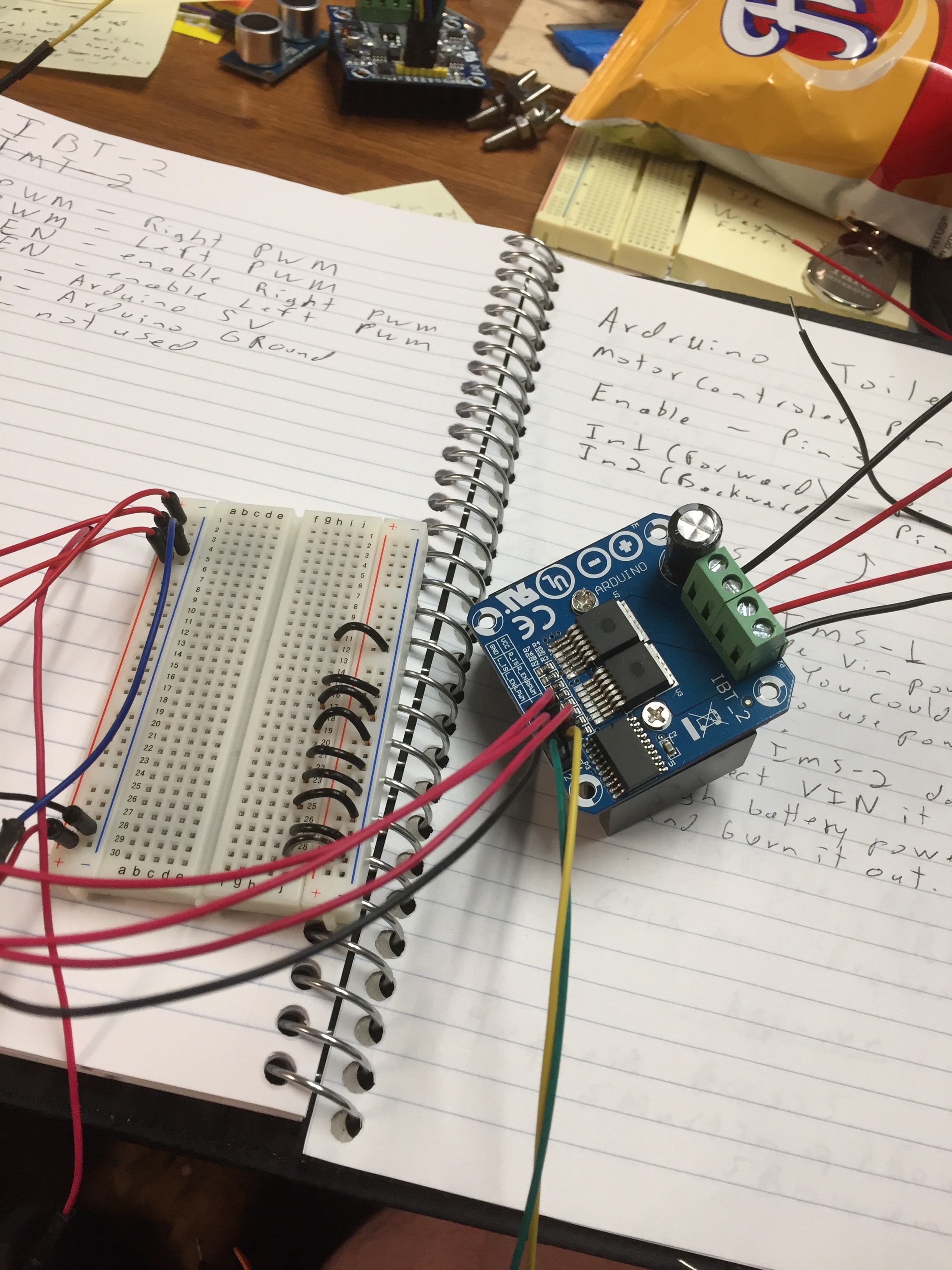
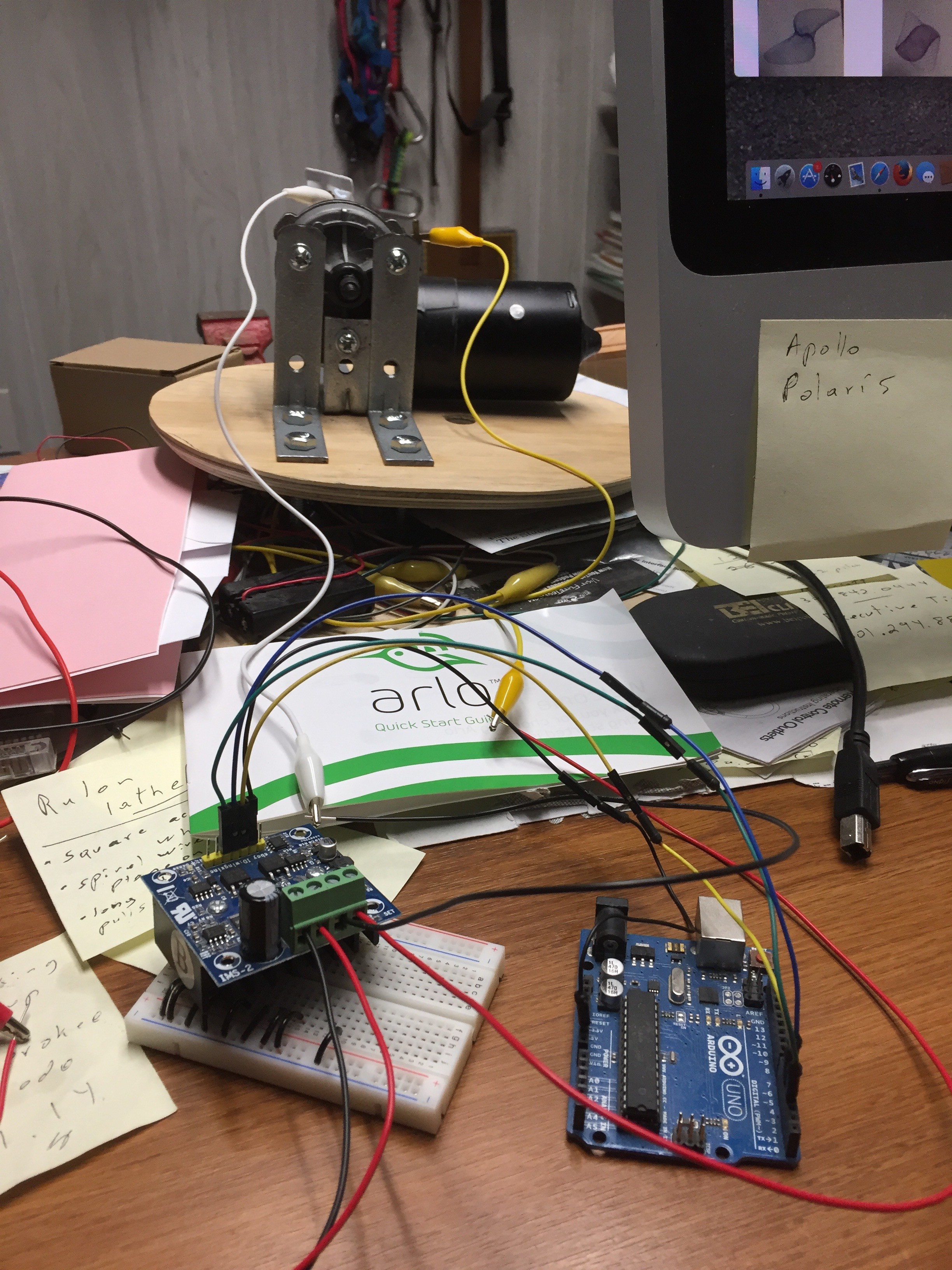
08/06/2017 at 03:13 • 0 commentsThis project used Adafruit wave shield, Sonic range sensor, two motor controllers (IBT-2 and IMS-2 more on this later), LEDs, two micro switches. My plan was to test each of these separately, I've worked with all of them in the past (except the IMS-2 motor controller), but wanted to refresh my memory.
The plan was to have a master Arduino then have it control the Arduino with the Wave shield. Their are limited pin's available with the Wave Shield.
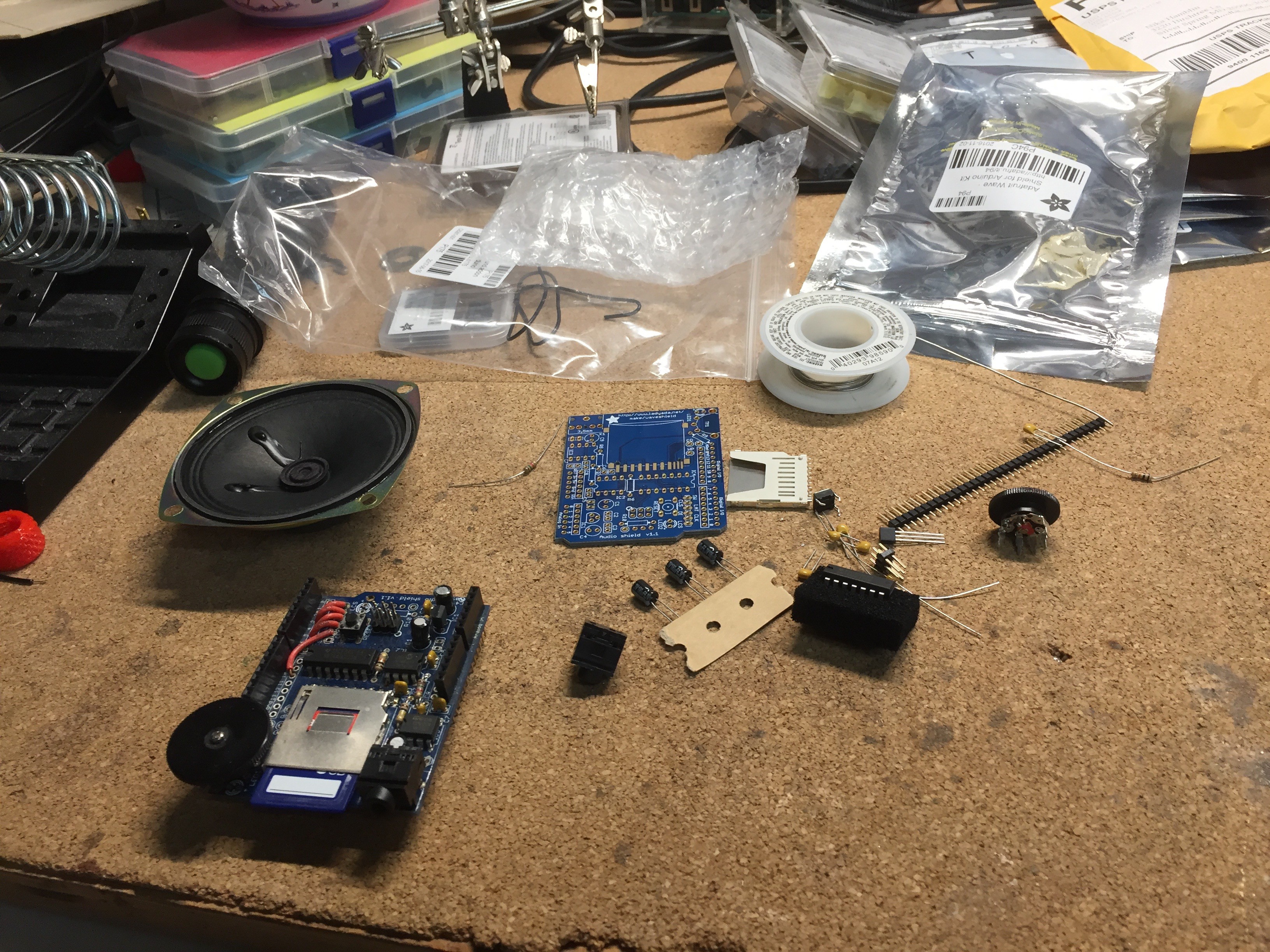
I build a Wave Shied in the past and planned on using it. I couldn't get the Wave shield working again. I suspect the problem was acidic solder flux, next time I will clean the flux off after finishing a project. I ordered a new one and with the speaker.
![]()
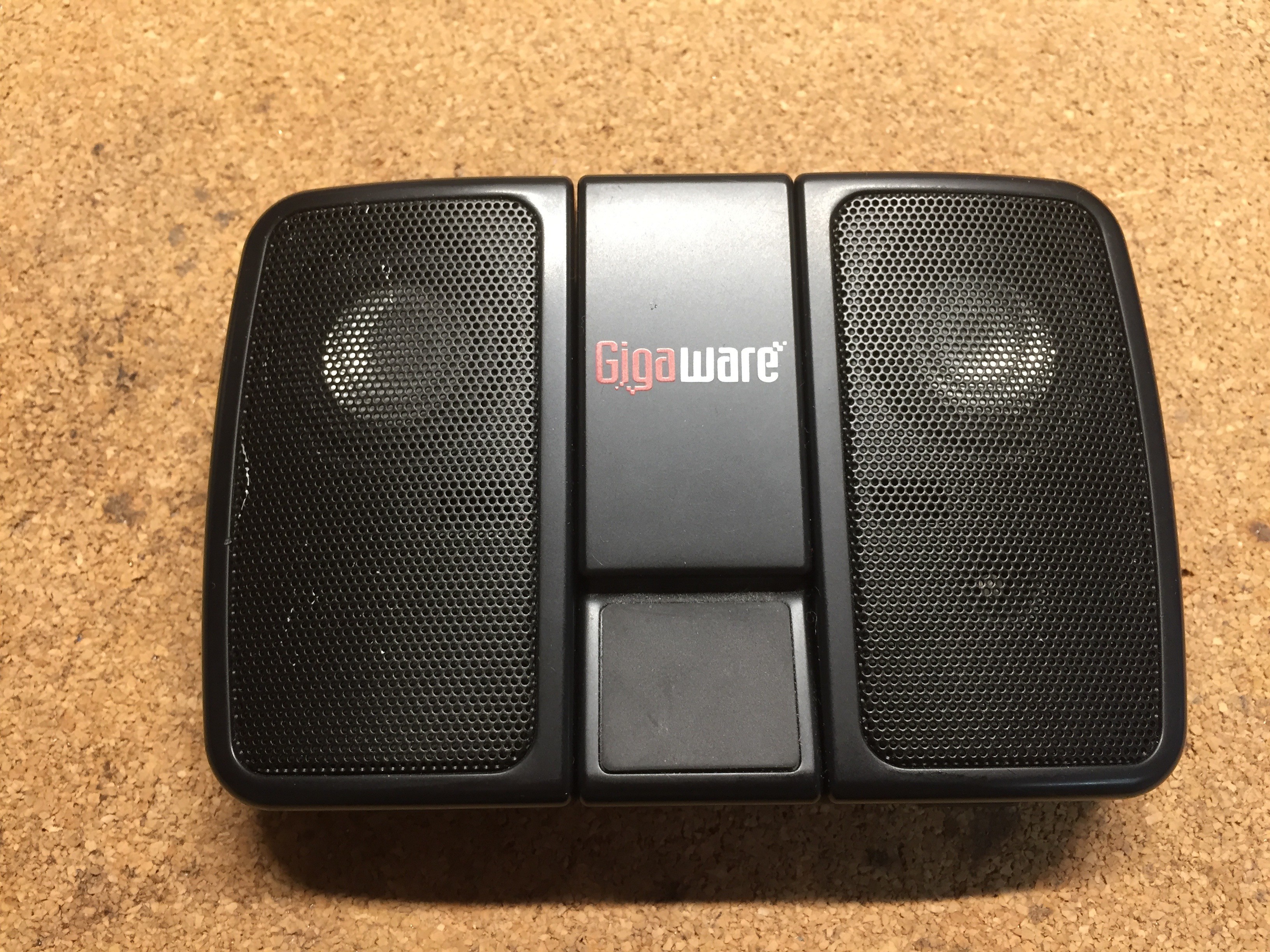
Then I purchased the Captain Underpants theme song to the movie, I also found the audio of a toilet flushing. I converted these so they would run on the Arduino. I also soldered wires for the speaker to the shield. When I tested this arrangement I was not happy with the speaker it was not very loud. I had a cheap portable speaker that I tested and the sound was much better, louder.
![]()
I then wanted to test being able to trigger the Wave Shield from the master Arduino. My plan was to simple set a Pin high. First I connected a micro switch to the wave shield arduino to use that to trigger it. I connected the switch to pin 12. Immediately had problems when the wave shield started up. After posting a question on the Adafruit forum, I got a quick answer. Pin 12 is a reserved pin used to read the memory card. I then read the spec sheet (like I should have from the start), I then used 8 to trigger. This test worked after this change. Then I went to trigger it from the master arduino. I spent an Saturday afternoon trying to get this to work unsuccessfully. I took a break came back and looked at it Sunday and released that I had not setup up a common ground between the two arduino's. Once I setup common ground the test worked.
Testing the IBT-2 motor controller was very easy and worked first time. The IMS-2 (I have the C version) was a different story. I could find very little documentation on this, everything I found was for the IMS-1. I followed the documentation for the IMS-1 setup, the test didn't work. It was right after this I released the Arduino was bricked. What I discovered is that the IMS-2 gets power from the high side automatically, when you put power to the high side you will see a LED light up on the motor controller. The IMS-1 (and IBT-2) both get power from the low side. The solution was simple do NOT connect the power to the VIN pin on the IMS-2 from the arduino. From now on I'm going to use the IBT-2 motor controller, it is very well documented.
![]()
![]()
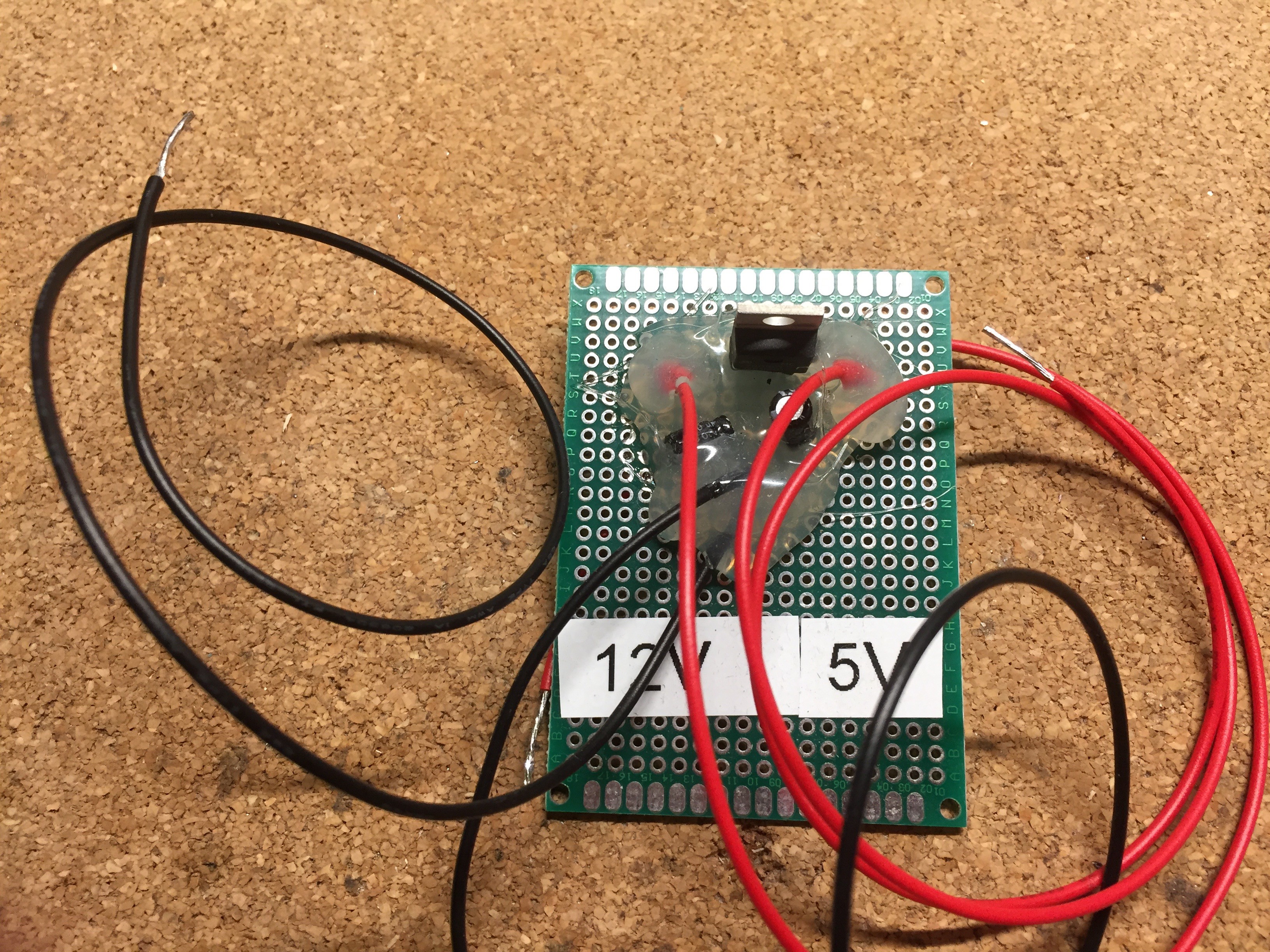
Lastly I need to work out the details of my power. I planned on run two 12v motor cycle batteries connected in Parallel. I also needed 5v power. I used a LM-7805-CT Linear Regulator and two micro capacitors on either side. This worked about extremely well, so well that I built a second one to use for another project.
![]()
-
Physical Build details
08/06/2017 at 00:33 • 0 commentsI am going to break up the project into three parts. Physical build, Arduino work bench sensors, and lastly integration of all the systems. For the Physical build I first needed to find a toilet to work with. I went to eBay, I found several around the $60 - 80 range but they where at least an hour away (probably longer). I looked on eBay for three days. Then I saw what I was looking for, one that was only about 15min away, and only cost $20. I brought that home and did a very good cleaning of it, I took the tank off the back and cleaned that area. Next I needed to work out how to attach the wiper motors. One of my design rules was I did not want to drill the toilet. I did this once on an earlier project and it is not easy drilling into porcelain.
![]()
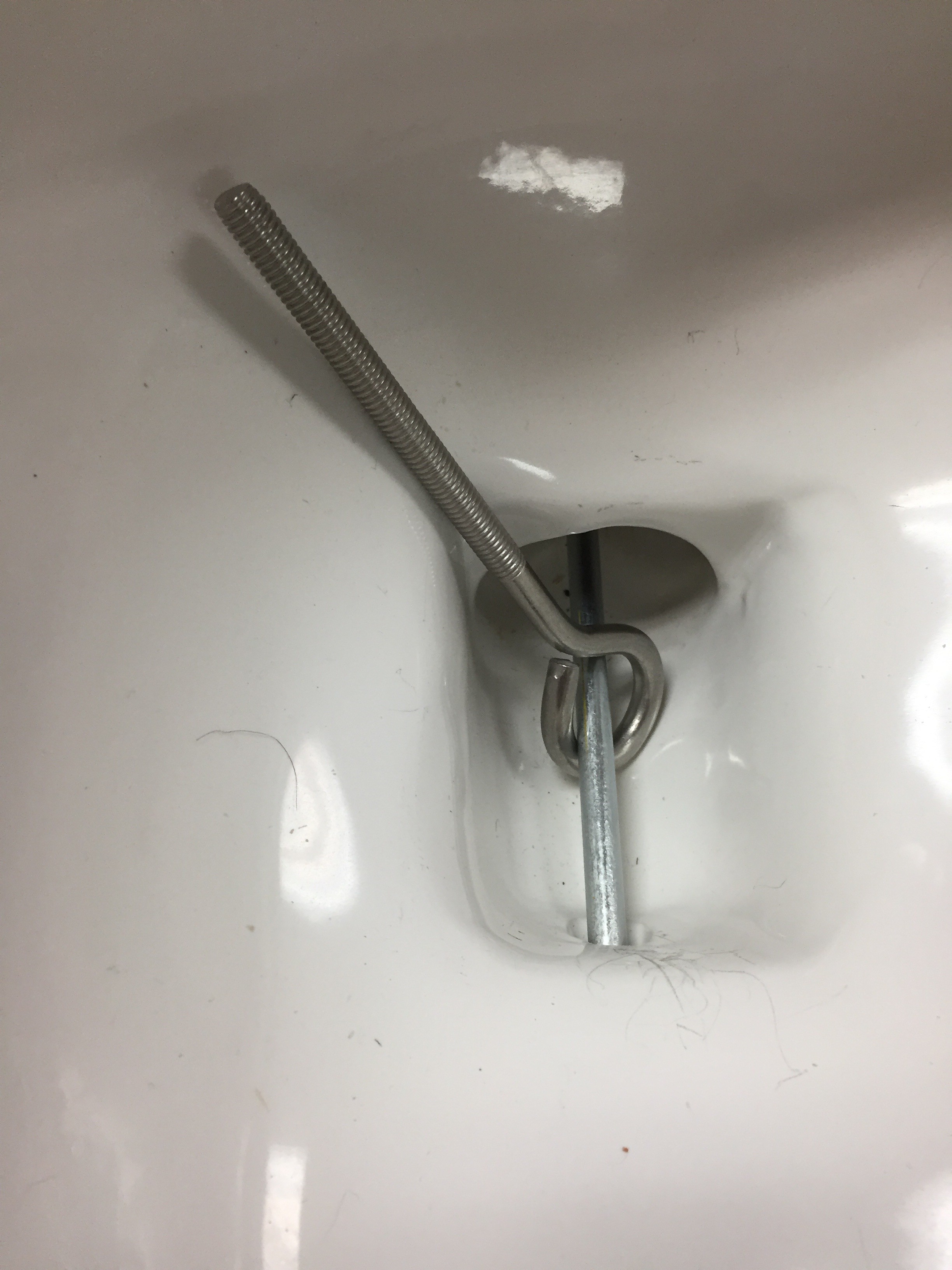
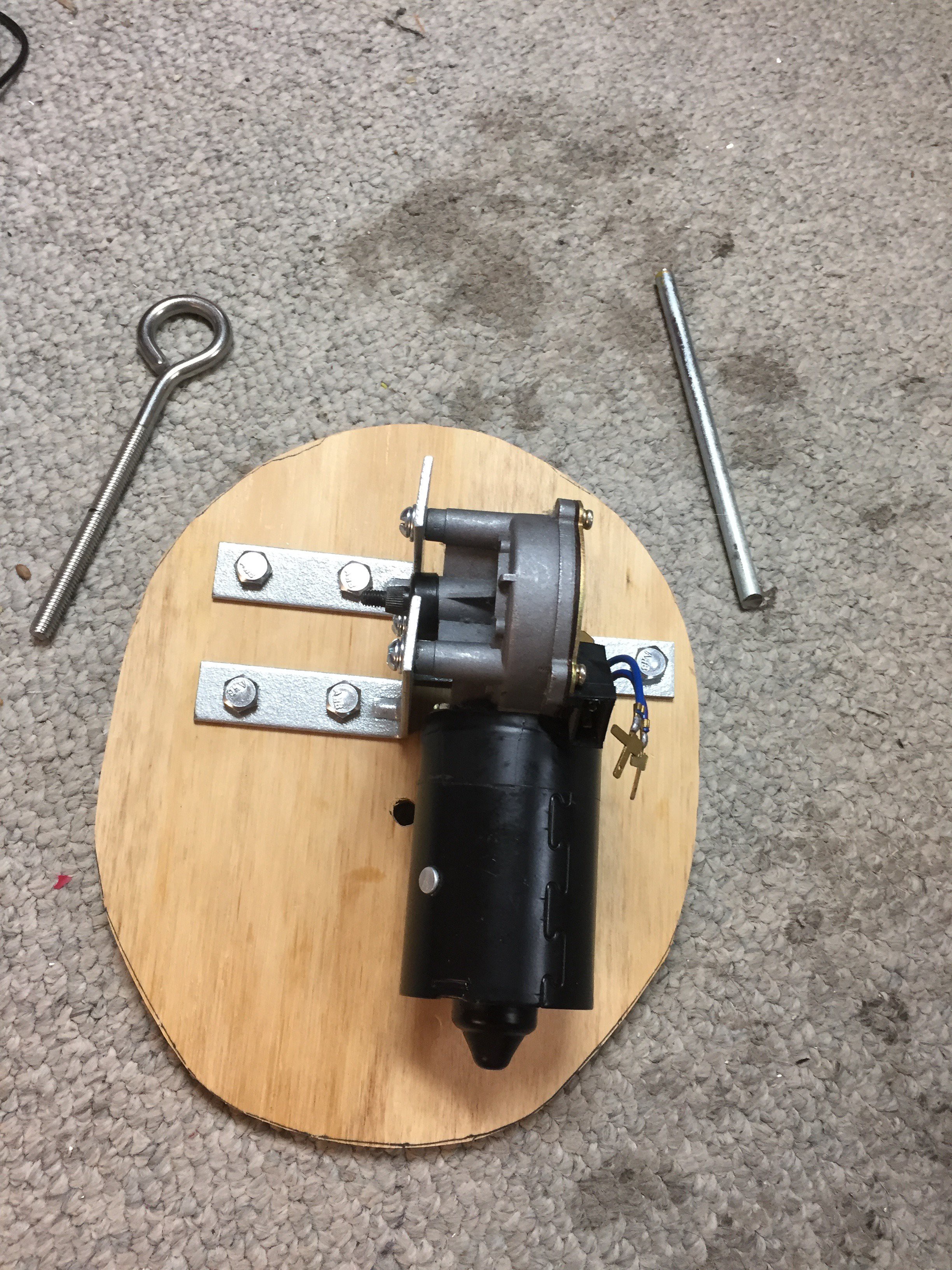
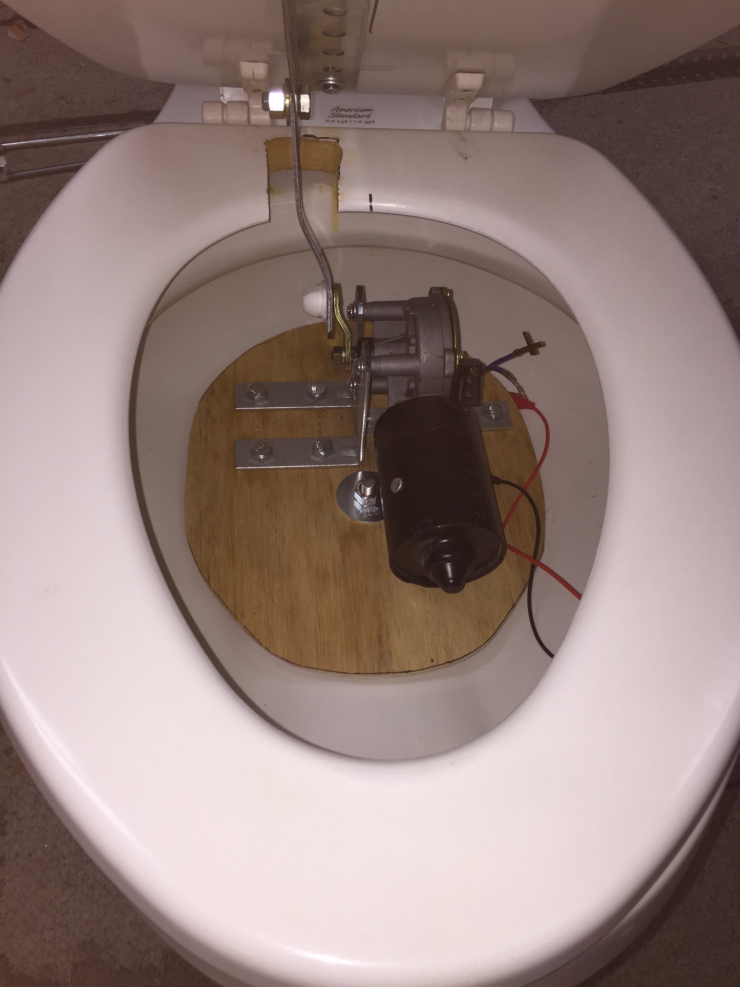
I had recently purchased a bench grinder. This came in very handy with this project. To mount the motors I purchased some 90 degree three whole brackets. I then had to drill holes to align correctly with the motor. This was a slow process, I cut off the excess bracket and used the grinder to round the edges. I used a oscillating belt sander to form the plywood mount for the bowl. This takes some time I wanted it too fit well all around so it wound not move. The mount for the bowl can easily be removed if needed. I later painted the bowl wiper motor and mount white to blend in better. I made one mistake I cut the bolt that holds the motor mount too short. I can get the nut started but it a delicate process, if it was an inch longer it would be easier to work with.
![]()
![]()
Attaching the wiper motor to the bowl lid was not that hard. I cut a piece of 1" flat bar about 9" long ( this is too long on purpose). I then drilled a 1/2 hole into one end. I went to auto zone and purchased
Dorman 49447 Windshield Wiper Linkage Bushing Assortment
I had to use an x-acto knife to cut off excess from the bushing, this held the flat steel bracket on very securely. I then cut 10" of Punched Angle zinc plate. This was perfect is had holes every inch. I spent about an hour walking up and down home depot trying to find items that I could use for my project that they where not intended for :D I attached the Angle bracket to the back side of the bowl lid with short screws making sure they did not go through to the other side. Then I noticed that the alignment was not correct the wiper motor was correct. I should have mounted the angle bracket differently than I did. I was able to put a Z bend in the bracket, I was very happy that I had a vise. I had to use hammer and care that the bend was where I needed it. Once this was done, I could test out how long the flat bar needed to be, I would hold the bowl lid up to the highest point. I then would take small cuts off the flat bar and then test fit again. Important to make sure the bowl wiper motor arm is up at the highest point while doing this. I then used the grinder to round and smooth all the edges. After drilling a 1/2" hole into the other end of the flat bar, I was able to attach the bowl wiper arm.
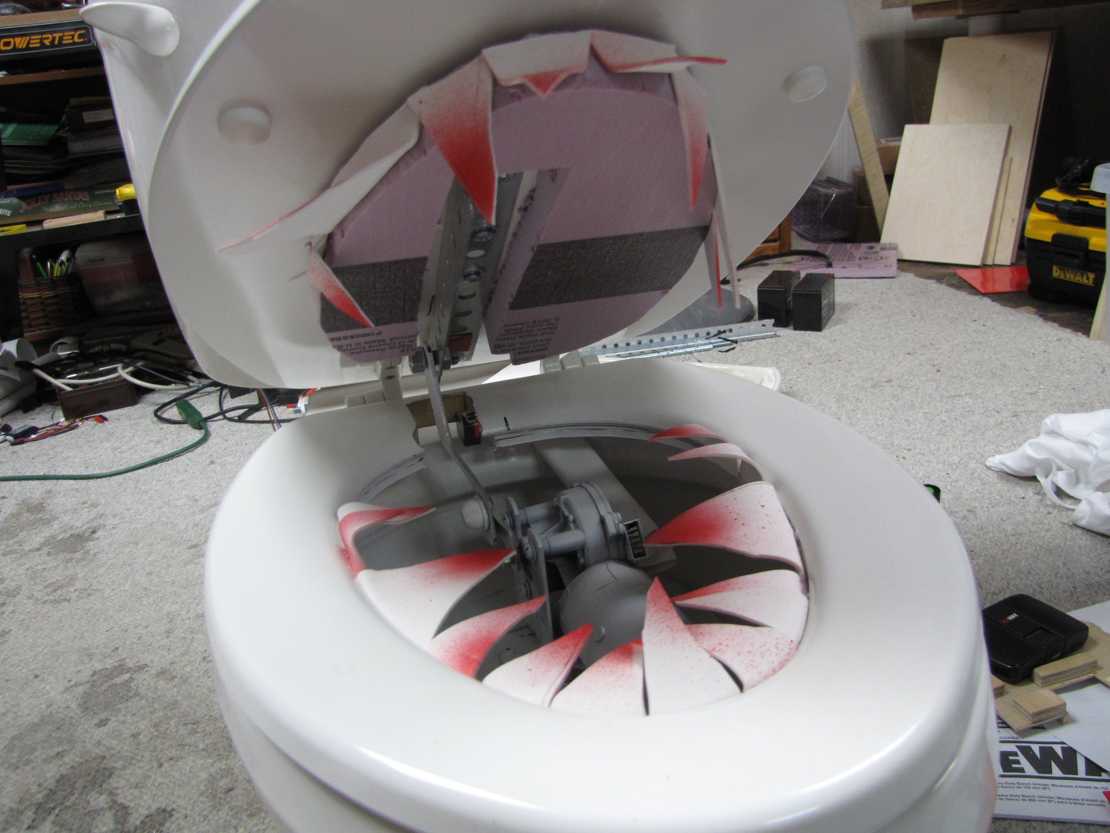
I also mounted a micro switch in the bowl seat, only the lid would move up and down. I needed the switch to let me know when the bowl lid was closed. This meant that I would have four wires that needed to be routed to the tank. I tried to route them trough the toilet, the passages are very small. In the end I went for 1 1/2 white heat shrink that I got from MicroCenter. I cut a notch in the back of the toilet seat for the microswitch. It took a bit of trail and error to get the switch into the correct position. Then I realized I can take the toilet seat off the toilet and get to the bottom of it, this made getting the correct location for the microswitch easy. Here is the bowl section completed and painted
Now on to the tank. I removed the rubber gasket that connects it to the bottom section, I then put two small 3/8 piece of plywood spacers on either side, and re-attached the tank. I wanted to have a gap so that I could route wires from the bowl into the tank.
I epoxied two five inch 2x2 diagonally to the bottom of the tank, on each side. Its important to leave room on the sides to be able to route the wires from the tank ( you don't want to pinch them).
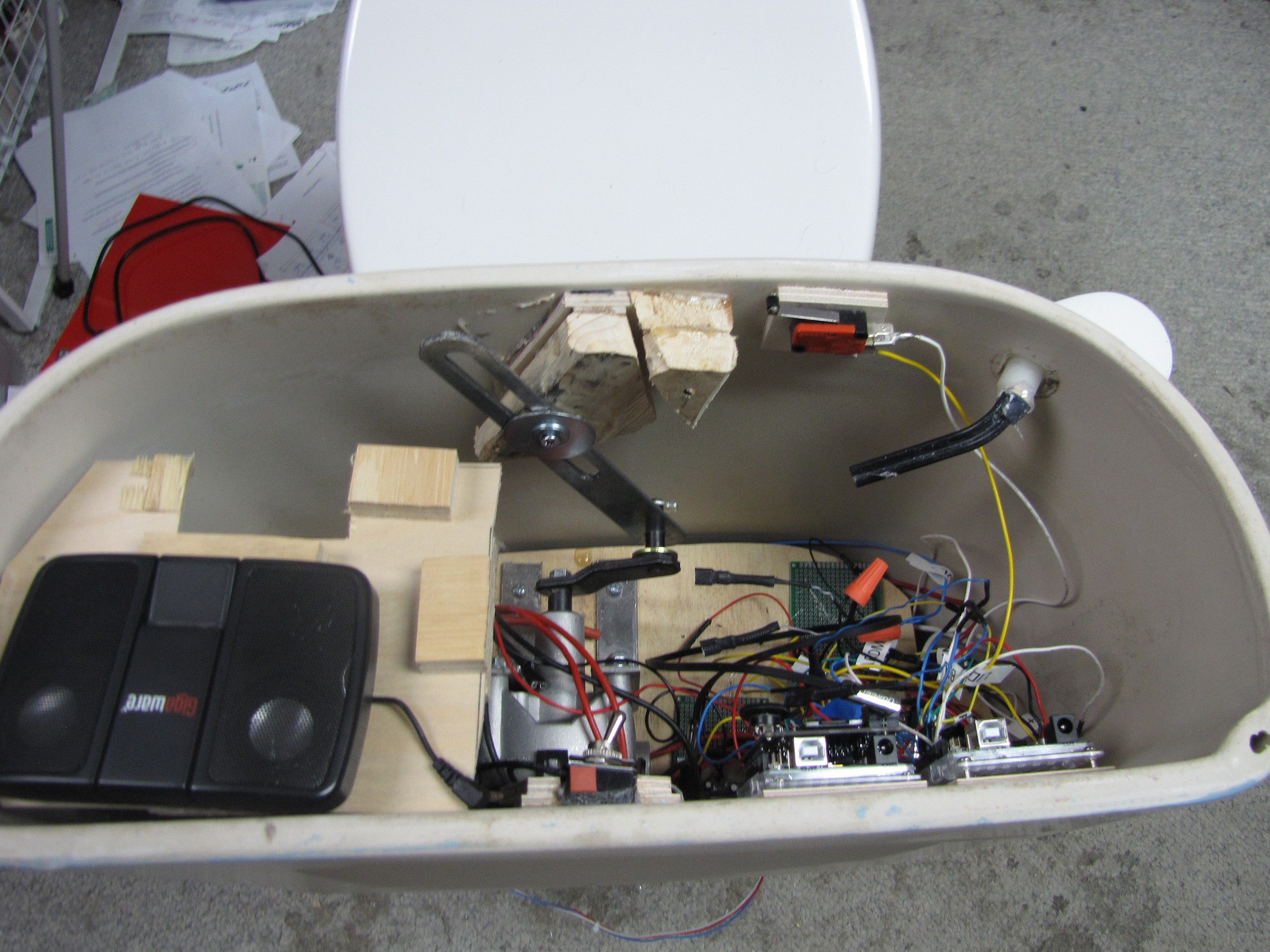
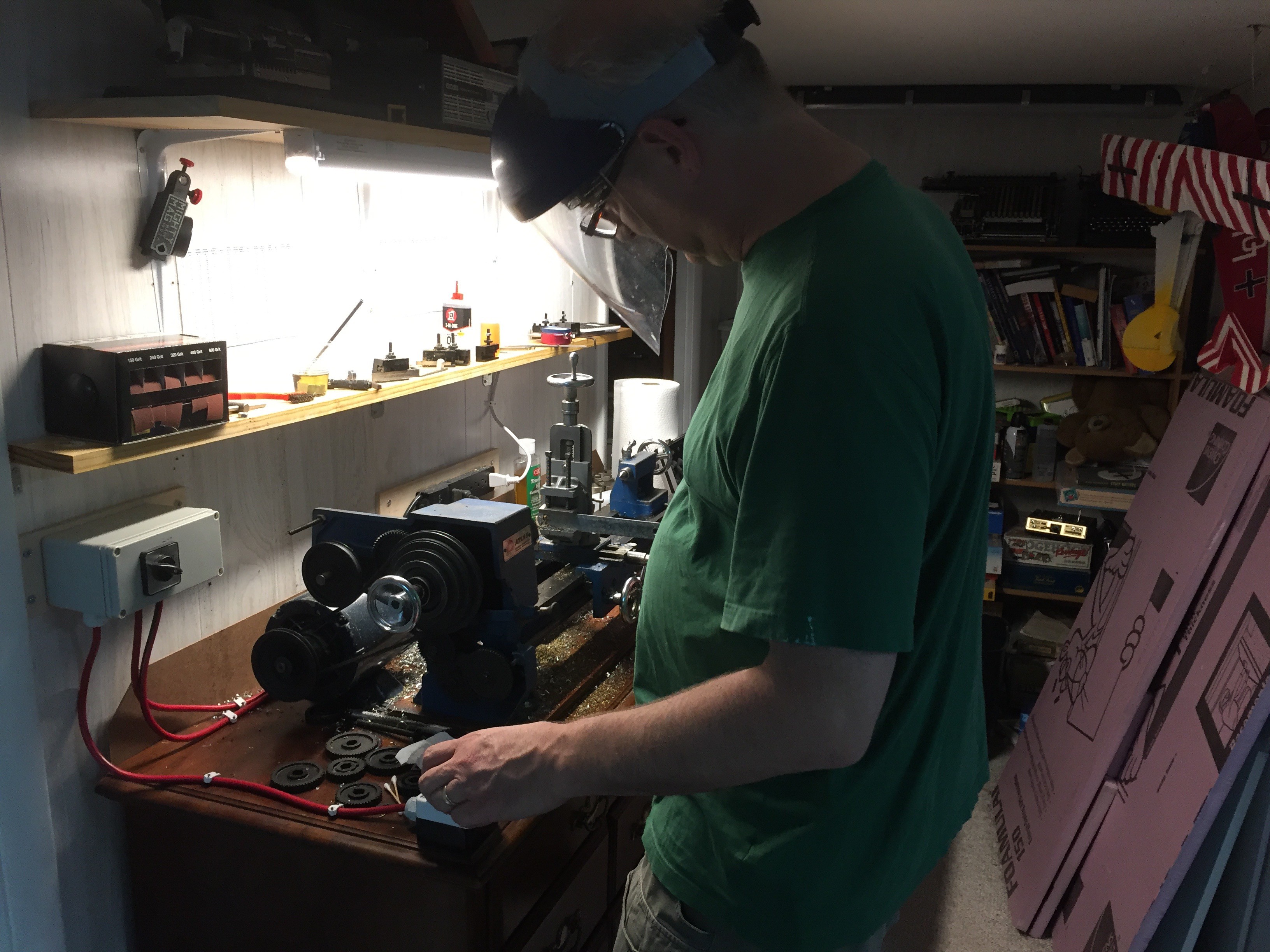
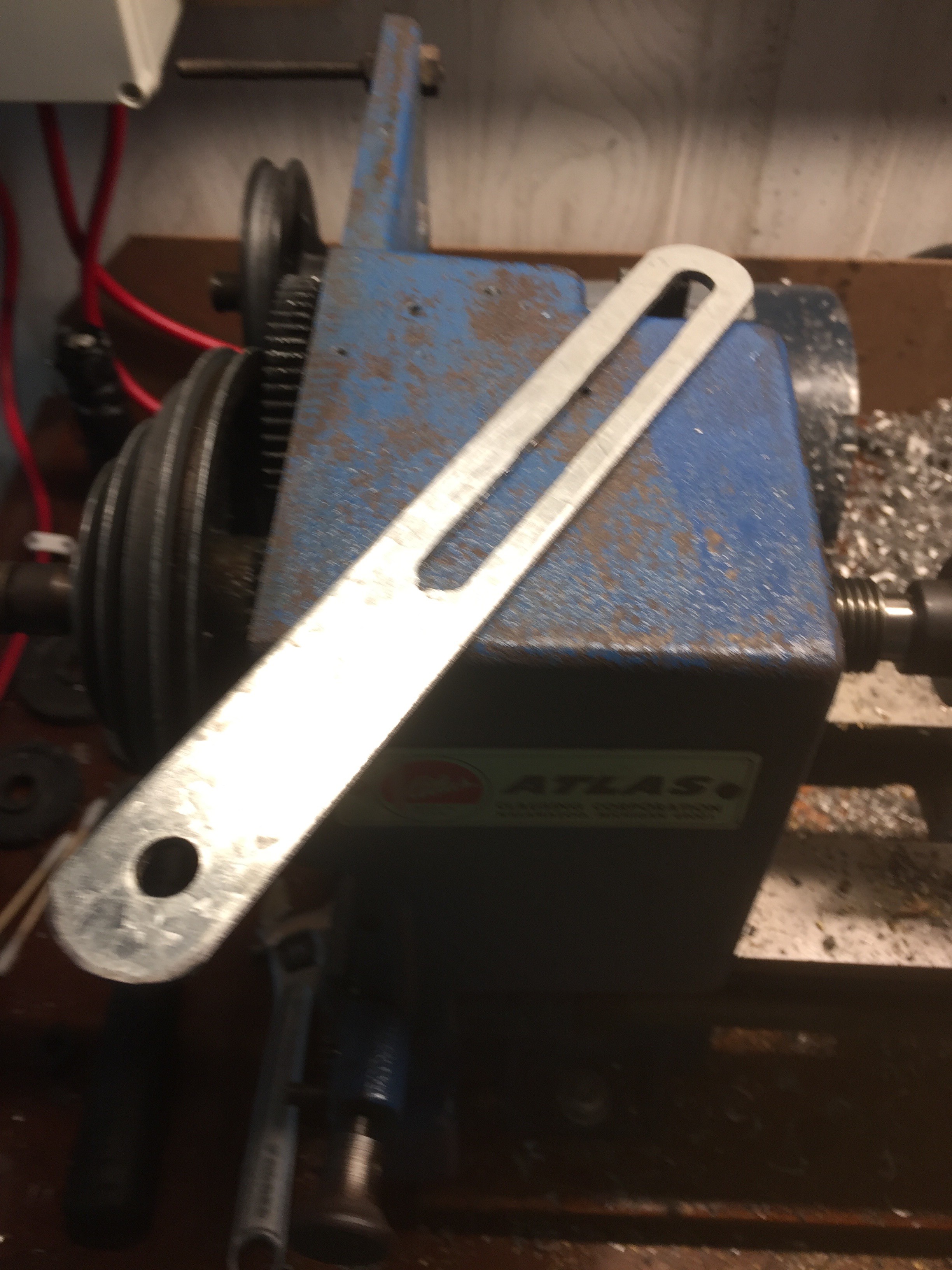
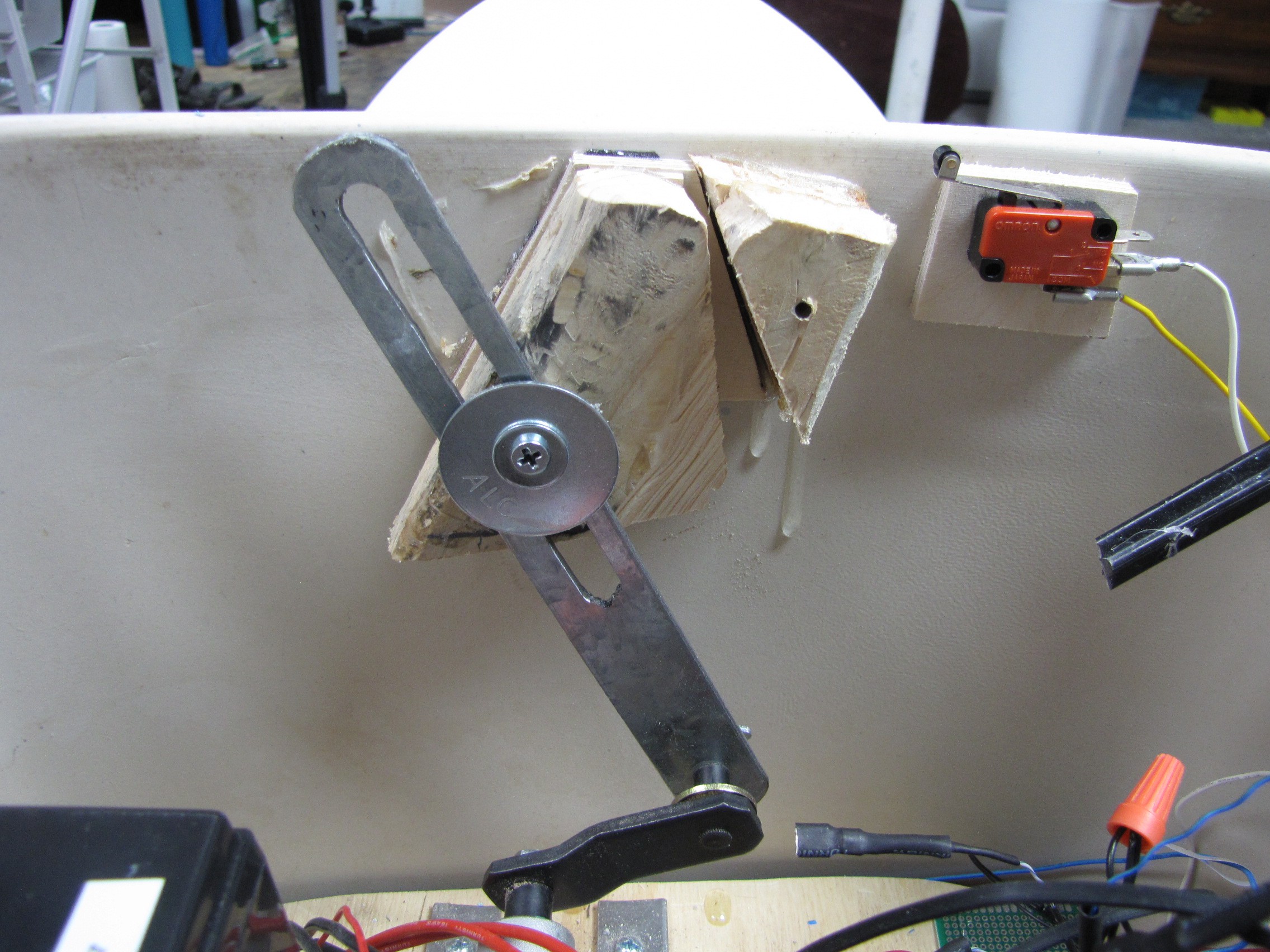
The Tank was the most DIFFICULT part of the build. The motor mounting was the same as for the bowl. The challenge came with the how to hold the arm and then lift the lid. The wiper motor had way more movement range than needed for the lid. It could easily pick up the lid and throw it off. I tried several methods to control the arm that at first seemed fine, then when testing with the lid on, I saw that their was too much travel. Cutting the arm shorter solved the range problem but create a problem with being able to control the arm. I spent several days trying to figure this out, I took a break for a day. Then I got the idea that if I milled a slot in the middle of the flat iron I could put a screw in there and I would be able to control the bracket. We recently got a table lathe with a mill attachment, this solution worked out perfectly.
![]()
![]()
![]()
When I mounted the motor on the plywood for the tank I purposely left an area that would just fit a 12v motor cycle battery laying on its side, then on the other side I would locate the Arduino's motor controllers etc. In the end I cut two pieces of 3/8 plywood that cut a little larger than an arduino foot print. I then hot glued these to the back side of the tank. I used small screws too attach the arduino's to these pieced of wood. This way I would have easy access to the arduino's. One frustrating issue was the new arduino's come with a nice clear plastic tray. I assumed the arduino was securing attached to the tray. This is not the case, I put a spot of hot glue between the tray and the arduino. Now the arduino's will stay in the tray, and if need too I can get them out of the tray.
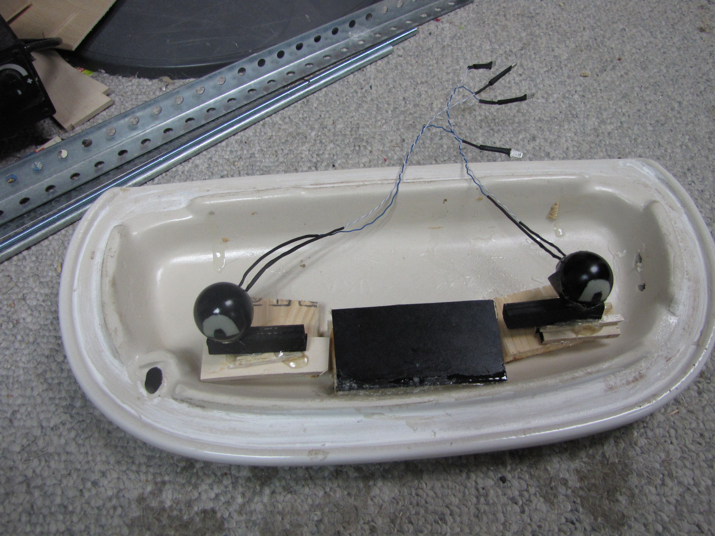
The last build part was the Eyes. I thought of several different ideas. I really wanted something that was reliable/solid and easy. I built some Ping Pong Eye decorations for halloween a couple of years ago. So I went with that. One unexpected problem was finding ping pong balls in summer, I wanted simple white ping pong balls all I could find was glow in the dark. I tried these out after painting, they did not look good. In the end I use one set from my halloween set.
I tried out mounting the eyes to the back of the tank lid. First I mounted the flat on the lid, when I tested this with the Lid up it did not look good. The eyes where looking up. I then tilted the eyes down by about 3/8 (used a square piece of balsa), this worked out very well. I then hot glued the eyes in place, this is a bit tricky since the eyes are not attached. I had to redo this a couple of times to get the look I was going for. FYI, be careful the eyes stick out and later when working on the electronics its easy to knock the eyes loose.
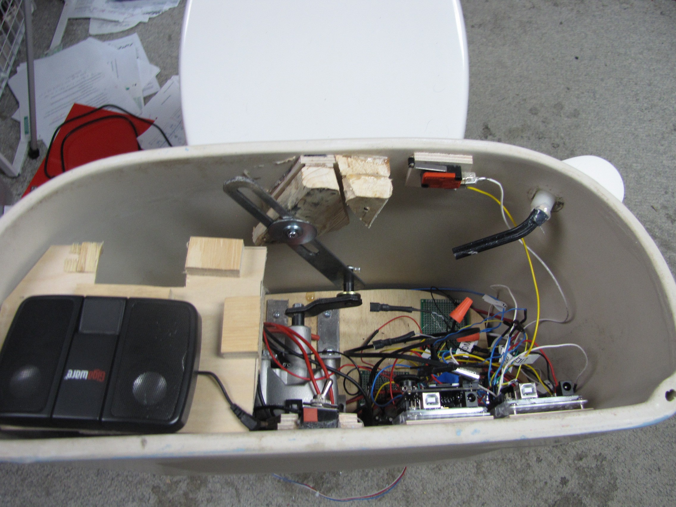
This is the final build of the tank. I built a small plywood platform for the speaker. Great care needs to be taken to keep all wires away from the motor linkages. The motor will happily grab anything and tear it apart. I learned this the hardware with a earlier set of Eyes. You can also see the microswitch in this picture for the Lid. I'm doing dead reckoning with the wiper motors, I use the switches to know when the lids are closed.
Captain Underpants Toilet
Arduino controlled Toilet using wiper motors and wave shield, range finder. Eyes made out of ping pong balls with green LEDs
