Christoph Tack
-
Validating the prototype
03/17/2018 at 21:04 • 0 commentsPrinted board assembly
Assembly is fairly easy. Be careful buying the BAT46W in the correct package. I've updated the PCB to revision /1, replacing the BAT46WJ (SOD-323) to BAT46WH (SOD-123). The -WH variant is bigger and easier to solder by hand.
Programming the board
I explained the procedure already in a previous log. To connect the programmer to your ATTINY85, you can use a Pomona SOIC-clip as shown on the image below.
Measuring interrupt frequency
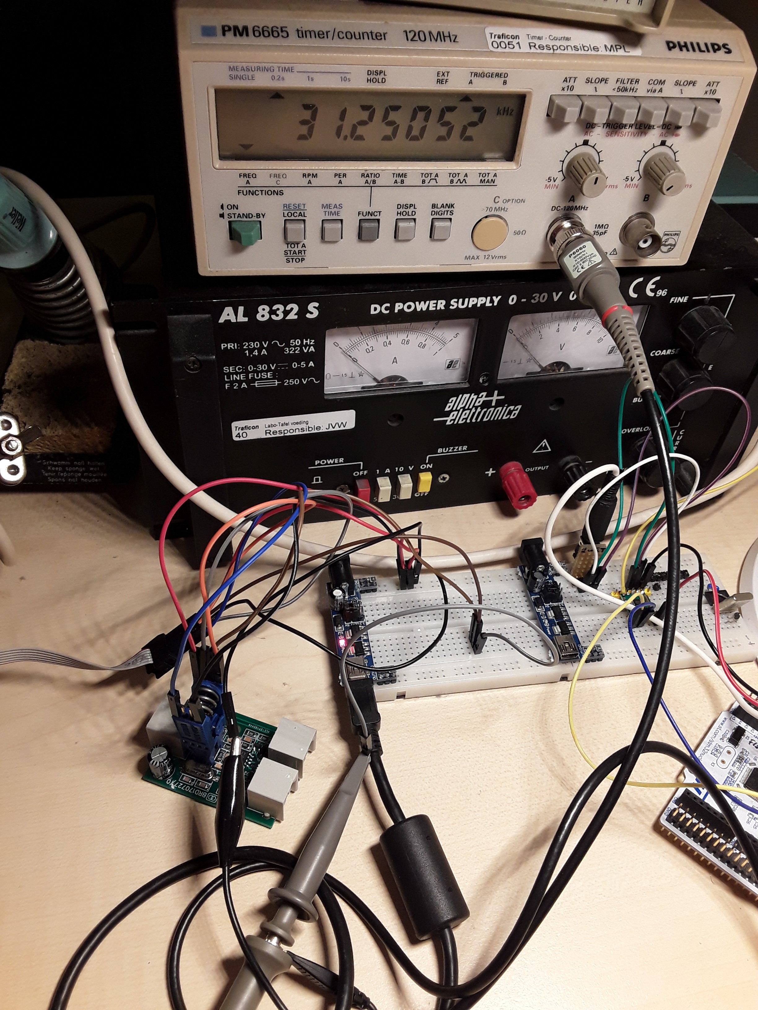
To check if the crystal has the correct load capacitors attached. A special debug firmware is loaded into the device which generates a square wave with a frequency that should be 31.250KHz.
![]()
Interrupt frequency should be 31.250KHz Adjusting DTMF-amplitude
Someone reported that the DTMF-amplitude was too large for their application. Increasing R10 from 10K to 100K and R12 from 10K to 15K fixed that.
Mounting in the housing
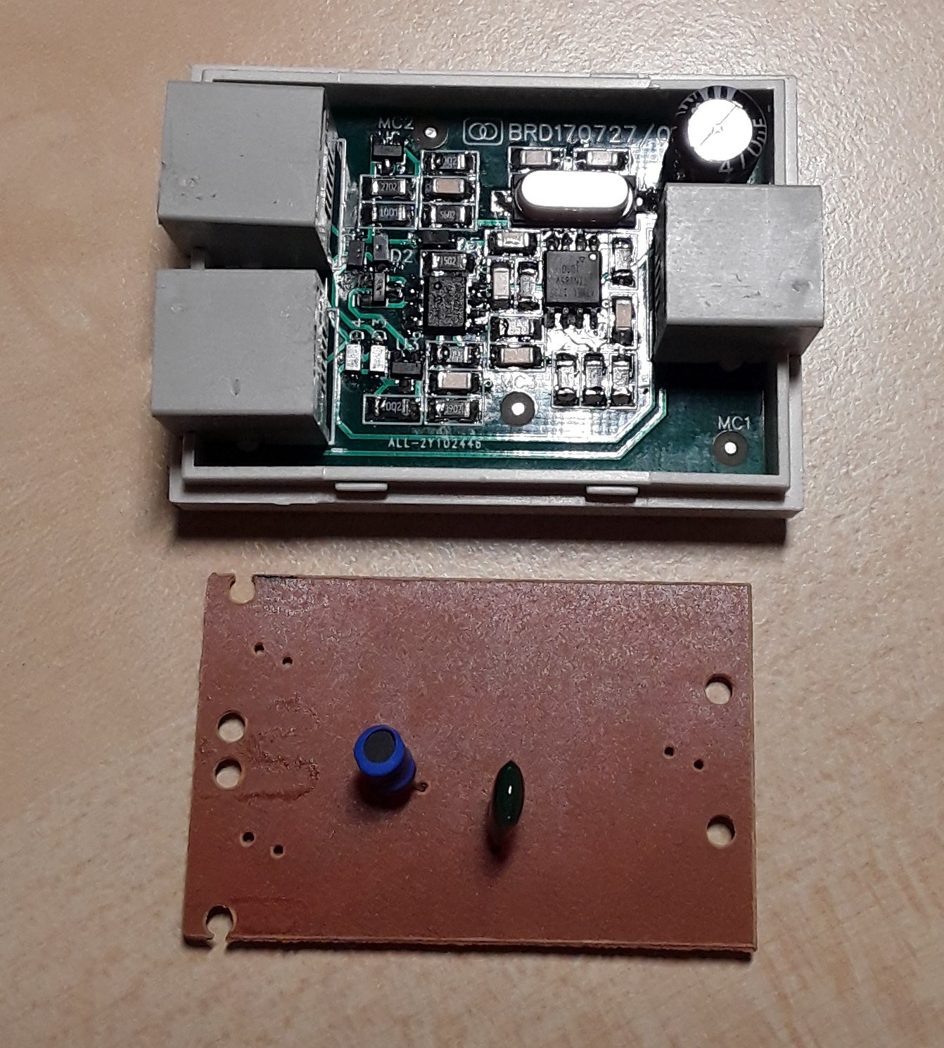
The housing originally contained an ADSL-splitter. It can be bought for a few cents from AliExpress. Its PCB has been removed. The modular jacks have been transferred to the pulse-dtmf-converter.
![]()
Pulse-dtmf-converter in its opened housing.
The PCB that was originally mounted is shown below it.Finishing up
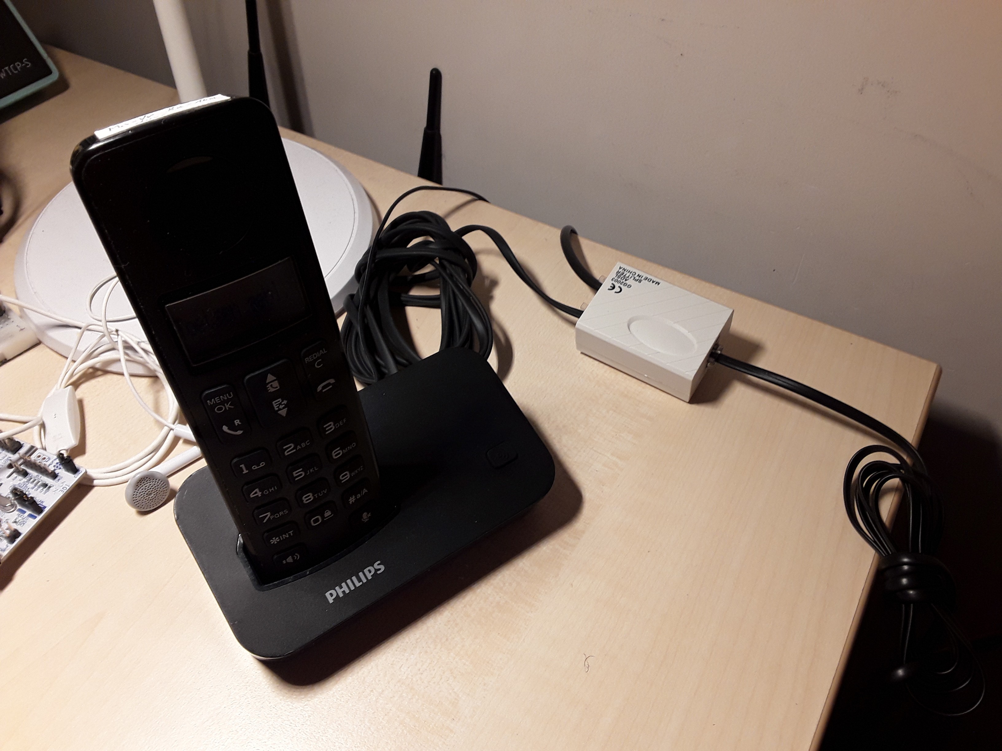
The Philps DECT-phone, which uses tone dialing is connected to the "PHONE"-port of the converter, as indicated on the bottom of the housing.
The FXS-port of the internet gateway is connected to the "MODEM"-port.
The pulse dialing phone is connected to the "LINE"-port.
![]()
Pulse-dtmf-converter in use... Making a few test calls assured me that both phones are working well.
That's all, folks.
-
Implementing sleep modes
02/06/2018 at 19:50 • 0 commentsThe nature of pulse dialing is such, that every pulse interrupts the power supply for 70ms. The pulse rate is 10pps, which means that during dialing, the MCU only gets power 30ms every 100ms. During the 70ms power gaps, the MCU has to survive on a 470µF capacitor.
Using sleep modes would allow us to choose a smaller supply voltage to reduce power consumption and to leave more headroom for the pulse dial telephone. Another option would be to decrease the elco and save cost.
Adding Sleep functionality in main loop
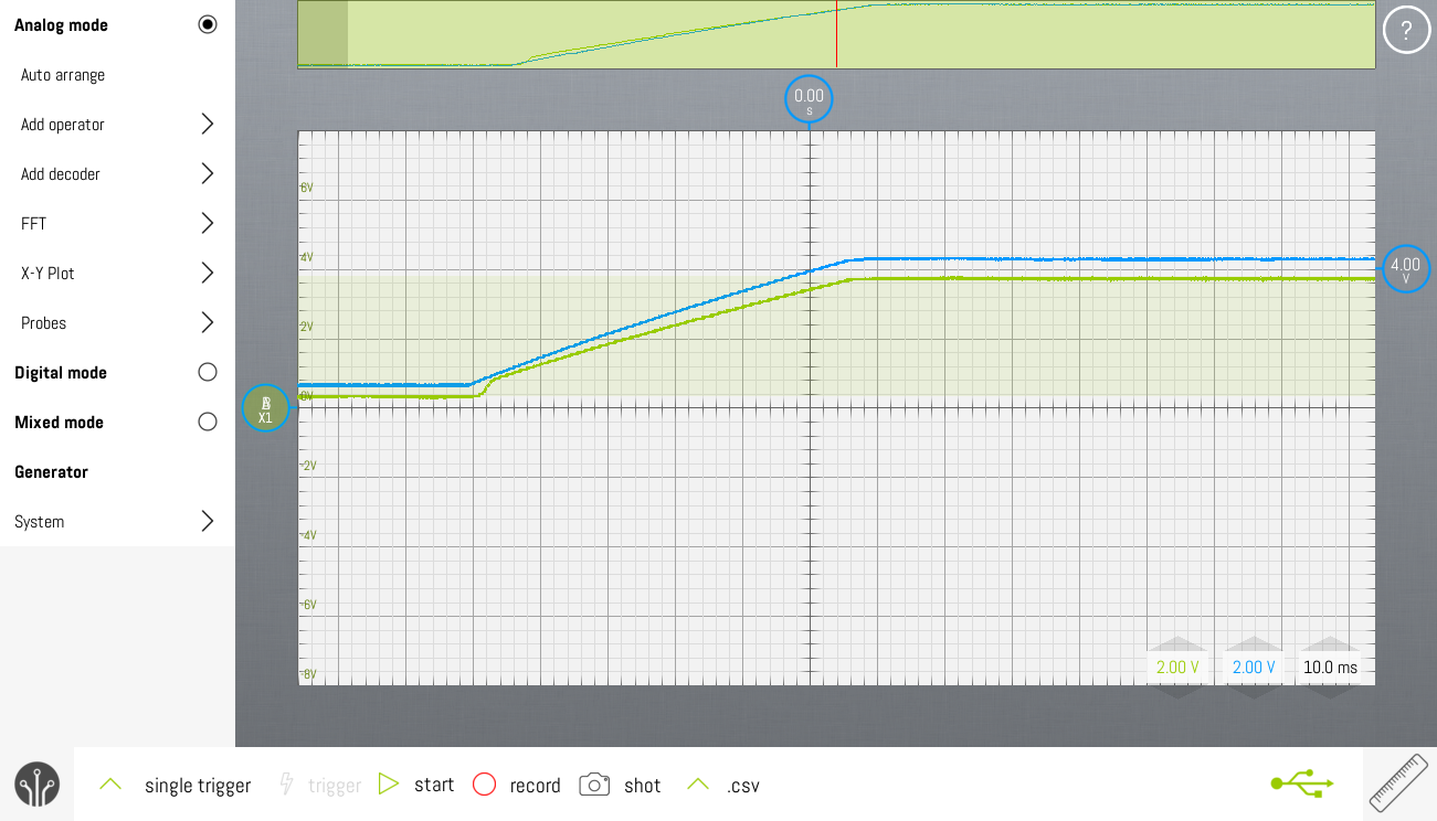
The rotary dial functionality is using Thomas Fredericks's Bounce2 library. To function properly it requires an update() function to be called regularly. By adding the update() function in the loop() function of Arduino, it's called every few tens of microseconds. No mechanical switch is that fast, so a lot of MCU cycles are wasted there. The following oscilloscope screenshots show VCC (green) and the GPIO connected to the main power entry point before the rectifying diode (blue).

MCU remains in ACTIVE mode, VCC drops down to 3.08V The solution lies in adding a sleepNow() functionality in the main loop, which forces the MCU into idle mode when there's nothing to do. In idle mode, interrupts still wake the MCU.
Timer0 interrupt is in Arduino standard set up to be called every ms. So each ms, timer0 fires, which wakes the MCU. The MCU calls the Bounce2.update() and goes to sleep again. Simple but effective.

MCU using IDLE mode, VCC drops only downto 3.57V -
Connecting to the FXS
02/03/2018 at 20:40 • 0 commentsFail...
- Connecting to the SLIC KS-0835F: everything works perfectly.
- Connecting to the FXS port of the internet gateway: FAIL
- The DTMF-converter doesn't start up reliably. It sometimes runs in bursts, as if the crystal doesn't start reliably.
- The number doesn't get dialed.
Issue 1: Startup problem
There's no reset circuitry present on the breadboard. The BOD is disabled as well.
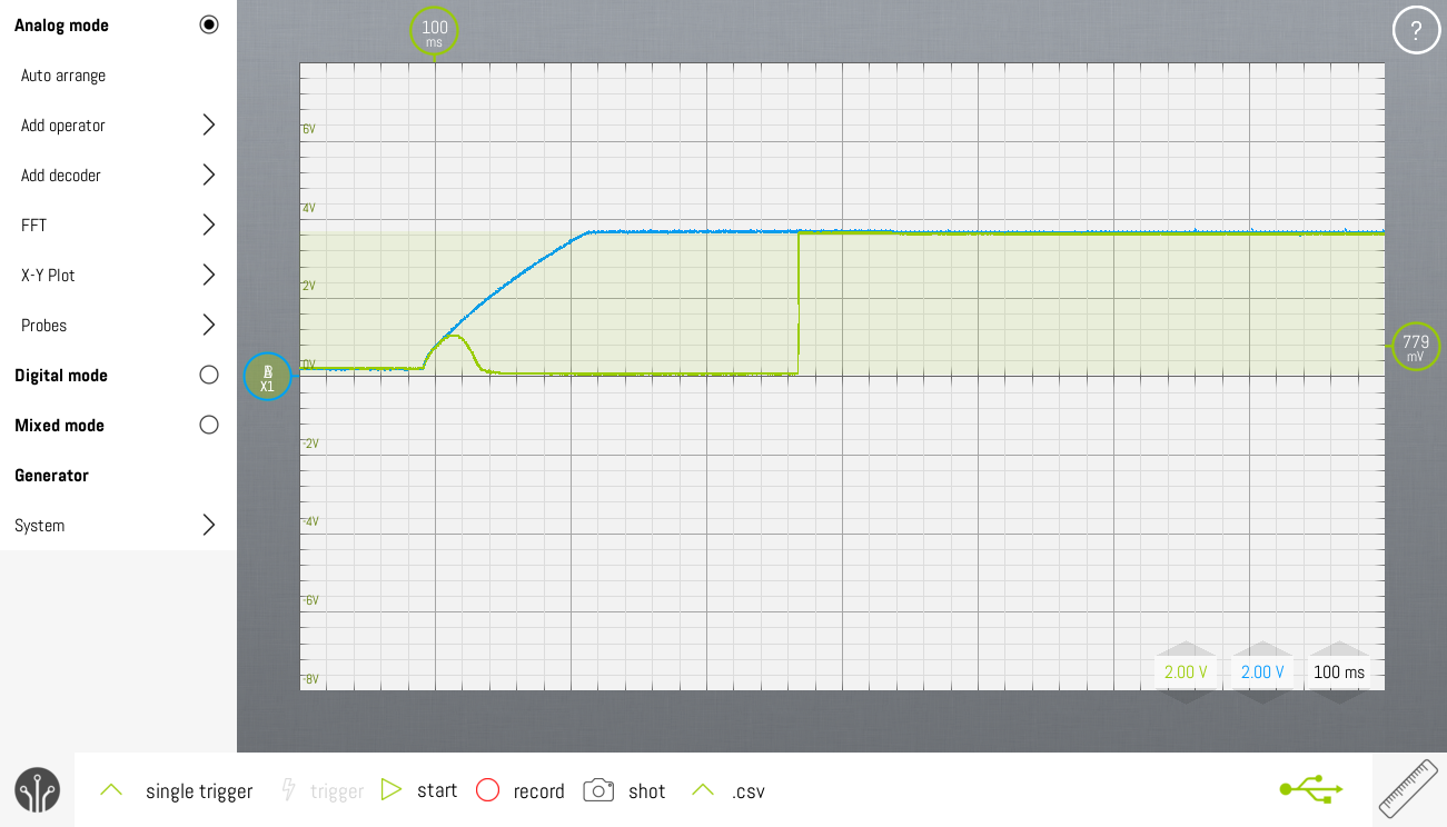
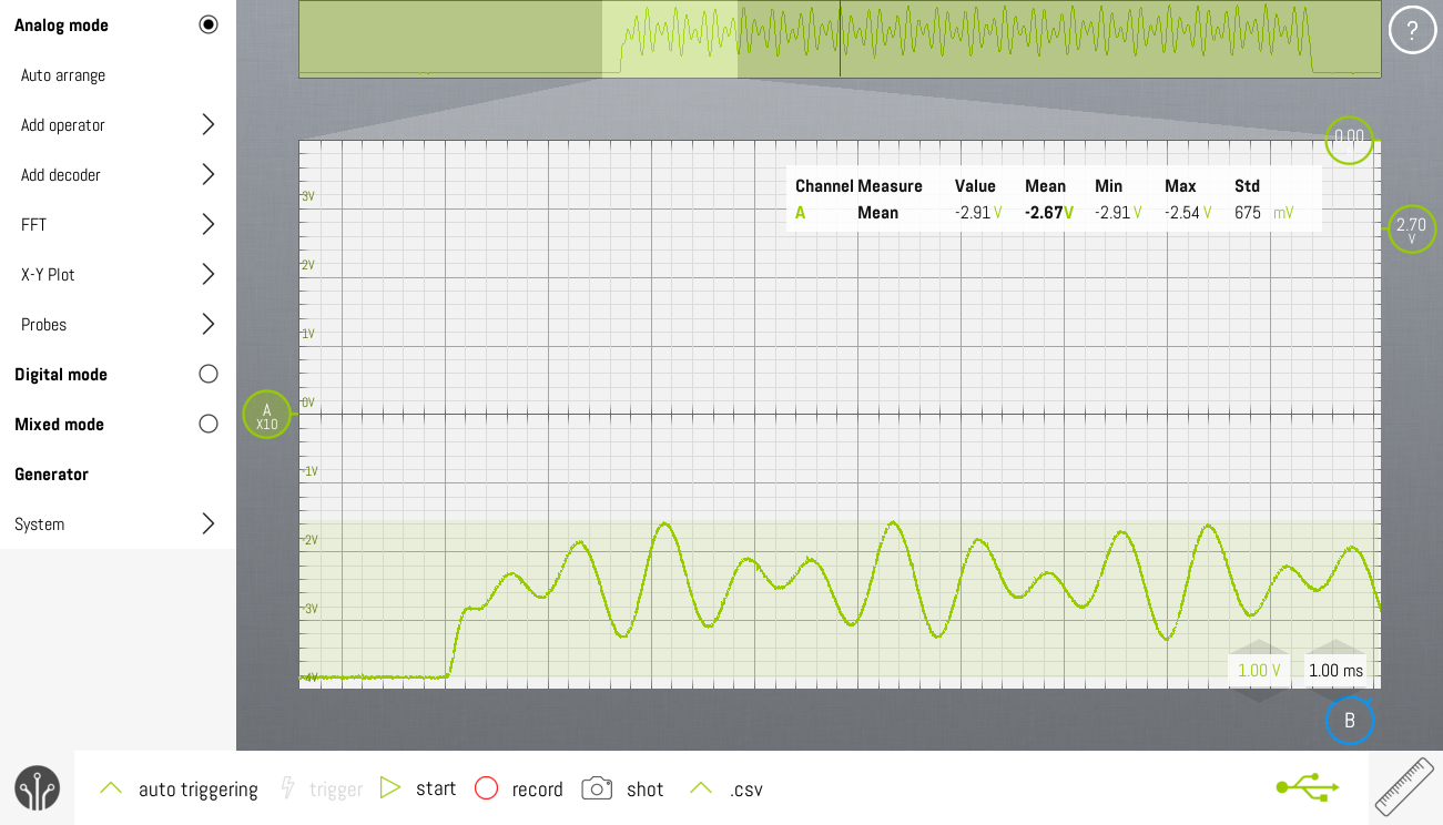
![]()
No reset controller, problems guaranteed... (blue=VCC, green=RST) The reset level (in green) follows the power supply voltage (in blue). Due to the charging of a 470µF capacitor, voltage ramp up is very slow. Nearly 60ms before full voltage is reached.
An option is to add a reset controller which has a timeout of 100ms. The reset trigger level should be 2.6V. This will avoid spurious resets during pulse dialing.
![]()
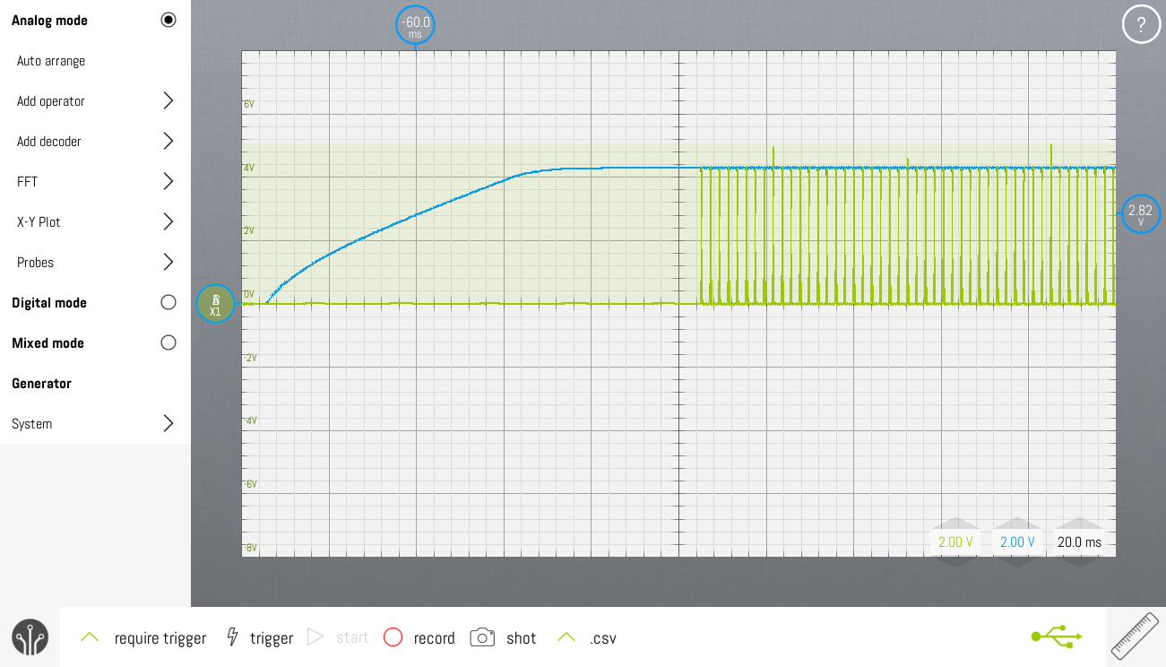
With a reset controller, the CPU starts up reliably. (blue=VCC, green=RST) An alternative approach is to use the 2.7V BOD in the attiny85.
![]()
BOD 2.7V enabled, BLUE=VCC, GREEN=DEBUG GPIO Using the BOD seems to work as reliably as the external reset controller. Using the BOD saves us four components in the BoM.
Remark:
The AVR-ISP MkII automatically generates a reset pulse at power up of the MCU. Be sure to disconnect the programmer during testing.
Issue 2: FXS doesn't recognize DTMF
This problem has two causes:
DTMF signal too weak
Connecting the Philips DECT to the SLIC again showed that the DTMF-signal that this design generates is too weak. Increasing the resistor between the reference and cathode of the bottom TLV431 to 39K solves this problem.
DTMF timing incorrect
The original idea was to generate a DTMF-digit immediately after a digit has been dialed. The DECT doesn't work that way. You form the number first. After that you "pick up" the horn, which initiates the DTMF-sequence of your formed number.
The pulse-dtmf-converter successfully dialed my cellphone when it was configured in the same way.
Finally...SUCCESS
-
Programming the Attiny85
01/29/2018 at 19:59 • 0 commentsArduino
The attiny85 is not supported on Arduino by default. Download the library from github and install it.
Programming connections
Signal ATTINY85 AVRISP mkII MISO 6 1 VCC 8 2 SCK 7 3 MOSI 5 4 RST 1 5 GND 4 6 Programming instructions
- In the Arduino IDE make sure the following is set:
- Tools -> Board : "ATTiny25/45/85"
- Timer 1 Clock : "CPU"
- Chip : "ATtiny85"
- Clock : "8MHz (external)"
- B.O.D. : "B.O.D. Enabled (2.7V)"
- LTO : "disabled"
- Set the type of your programmer : "AVRISP mkII"
Burn the bootloader
Burn the bootloader (which is empty) to make sure fuse settings are correct.
Luckily, the arduino toolchain sets the correct fuse values. Using the Engbedded Atmel AVR® Fuse Calculator, you can check the fuse settings:
-U lfuse:w:0xff:m -U hfuse:w:0xd5:m -U efuse:w:0xff:mUpload the application
Be sure to write the bootloader first. Otherwise, the device will run at 1/8 of the desired CPU frequency.
Verifying CPU clock frequency
The internal RC-oscillator is not accurate enough to generate DTMF correctly over large temperature and voltage specs. For development purposes, a 12MHz oscillator can be connected to pin 2 of the Attiny85. Oscillators are quite power hungry. So, for rotary dial testing, in which the power supply is cut off during dialing, it should be powered from a separate 5V supply.
An 8MHz external clock would is a better choice. The attiny85V is not specified to work at 12MHz. When the supply voltage drops below 4V the MCU behaves inpredictably. With an 8MHz clock, the attiny85V has a much wider supply voltage range.
The MCU frequency can be checked with a timer/counter. A digital oscilloscope that only samples at 100Ms/s will not yield reliable results.
Verifying DTMF frequencies
The first step is to check the interrupt frequency, which is our PWM-frequency. This looked ok using the PM6665. It's more reliable to measure if OCR1A is forced to a fixed value so that a fixed duty cycle is being generated.
Next step is to verify the DTMF frequency. This signal can be measured at the non-inverting input of the opamp in the current source configuration. By leaving out one of the two frequencies of the DTMF signal, allows for easier measurement of the frequency of the restored waveform.
A final test was to generate the same DTMF-sequence as had been done before using the ProTrinket3V
The result can be heard here.
Decoding using multimon shows that the generated DTMF-tones are correct.
ctack@ctack-X550LD:~$ multimon -a DTMF -t wav DTMF_0123456789.wav multimod (C) 1996/1997 by Tom Sailer HB9JNX/AE4WA available demodulators: POCSAG512 POCSAG1200 POCSAG2400 EAS AFSK1200 AFSK2400 AFSK2400_2 HAPN4800 FSK9600 DTMF ZVEI CCIR SCOPE Enabled demodulators: DTMF sox WARN sox: Option `-s' is deprecated, use `-e signed-integer' instead. sox WARN sox: Option `-2' is deprecated, use `-b 16' instead. DTMF: 0 DTMF: 1 DTMF: 2 DTMF: 3 DTMF: 4 DTMF: 5 DTMF: 6 DTMF: 7 DTMF: 8 DTMF: 9 sox WARN rate: rate clipped 2830 samples; decrease volume? sox WARN dither: dither clipped 2441 samples; decrease volume? - In the Arduino IDE make sure the following is set:
-
Verification of the generated DTMF
01/20/2018 at 14:27 • 0 commentsThe SLIC has an audio output. Let's hook that up to the mic input of the laptop. As wikipedia shows, there are different pinouts standards for a TRRS 3.5mm audio jack. In other words, there's no standard pinout. Use a DMM to find out what pinout your laptop is using. My Acer has the following pinout:
- Tip = Left out
- Ring1 = Right out
- Ring2 = GND
- Sleeve = Mic in
In Ubuntu Linux, 5s of audio can easily be recorded by:
arecord -d 5 DTMF_0123456789.wav
To play back the file:
aplay DTMF_0123456789.wav
The microphone level might need some tuning.
Decode the DTMF-audio with:
multimon -a DTMF -t wav DTMF_0123456789.wav
multimod  (C) 1996/1997 by Tom Sailer HB9JNX/AE4WA
available demodulators: POCSAG512 POCSAG1200 POCSAG2400 EAS AFSK1200 AFSK2400 AFSK2400_2 HAPN4800 FSK9600 DTMF ZVEI CCIR SCOPE
Enabled demodulators: DTMF
sox WARN sox: Option `-s' is deprecated, use `-e signed-integer' instead.
sox WARN sox: Option `-2' is deprecated, use `-b 16' instead.
DTMF: 0
DTMF: 1
DTMF: 2
DTMF: 3
DTMF: 4
DTMF: 5
DTMF: 6
DTMF: 7
DTMF: 8
DTMF: 9
Decoding works perfectly.
Alternative DTMF decoders
- MT8870 DTMF Audio Decoder LCD 1602 Display Module for Fixed telephone mobile phone keypad Key value shows smart home
- wholesale 1pcs MT8870 DTMF Voice decoding module phone module
- You could also download a DTMF decoder for your smartphone from Google Play.
-
Realization of coupling DTMF to telephone line
01/18/2018 at 20:41 • 2 commentsSchematic explanation
Warning: This schematic is not a definitive version. Only the DTMF-generator has been implemented. There are no provisions yet for detection of pulses during dialing.
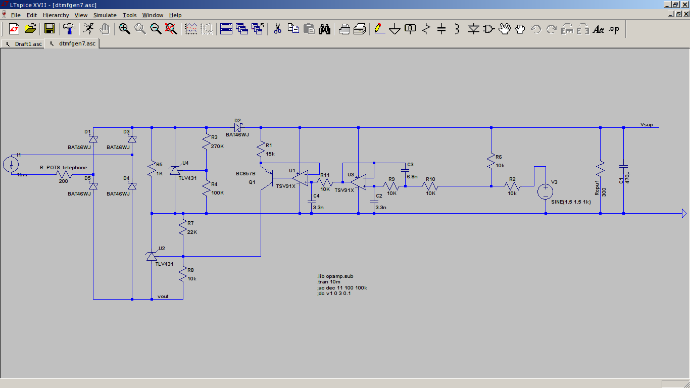
![]()
The schematic above couples DTMF to the telephone line.
- The current source on the left is the SLIC that sources 15mA to 30mA current.
- The R_POTS_telephone is the internal resistance of the off-hook telephone. You can see that the DTMF-generator is in series with the telephone line. When the telephone is on-hook, the telephone resistance is very high, so there's no loop current. This circuit doesn't consume power when the telephone is on-hook.
- The diode bridge rectifies the loop current, making this circuit insensitive to line polarity or line reversal.
- R5 not needed for generating DTMF, only during pulse dialing.
- U4, R3, R4 function as an adjustable zener. The "zener voltage" is set to 4.6V. This is the source of the supply voltage of the DTMF generator. So no matter what the loop current is, the zener behavior will limit the supply voltage to about 4.6V.
- D2 & C1 are not needed for generating DTMF. They keep the MCU going when the telephone is in pulse dialing mode. When these pulses are being generated, loop current is interrupted and the supply voltage of the DTMF-generator would collapse.
- Rcpu1 simulates the behavior of the MCU, drawing 10mA at 3V.
- You probably recognize U2, R7, R8 as an adjustable zener again. These three components couple the DTMF to the telephone line. We can modulate the U2-zener voltage, and hence modulate the total voltage over our DTMF-generator. This voltage is one-on-one transferred to the audio output of the SLIC. The drawback of this solution is that it adds about 2V to total voltage over the DTMF-generator.
- U1, R1, Q1 is a current source. By varying the current into U2, it's "zener" voltage will vary linearly.
- U3 with surrounding caps and resistors: An active low pass filter, desiged with Nuhertz Filterfree. For audio frequencies as used in this design, active filters are the way to go. Passive filters are either ineffective with RC or require very large inductors with LC realizations.
- R6, R2: Voltage shift and divider for the input signal to avoid exceeding the CM-range of the opamp.
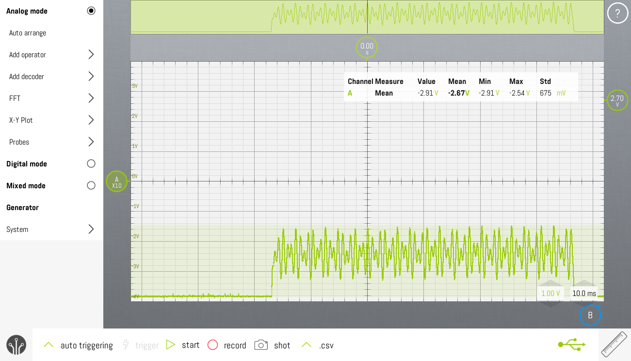
Measurements
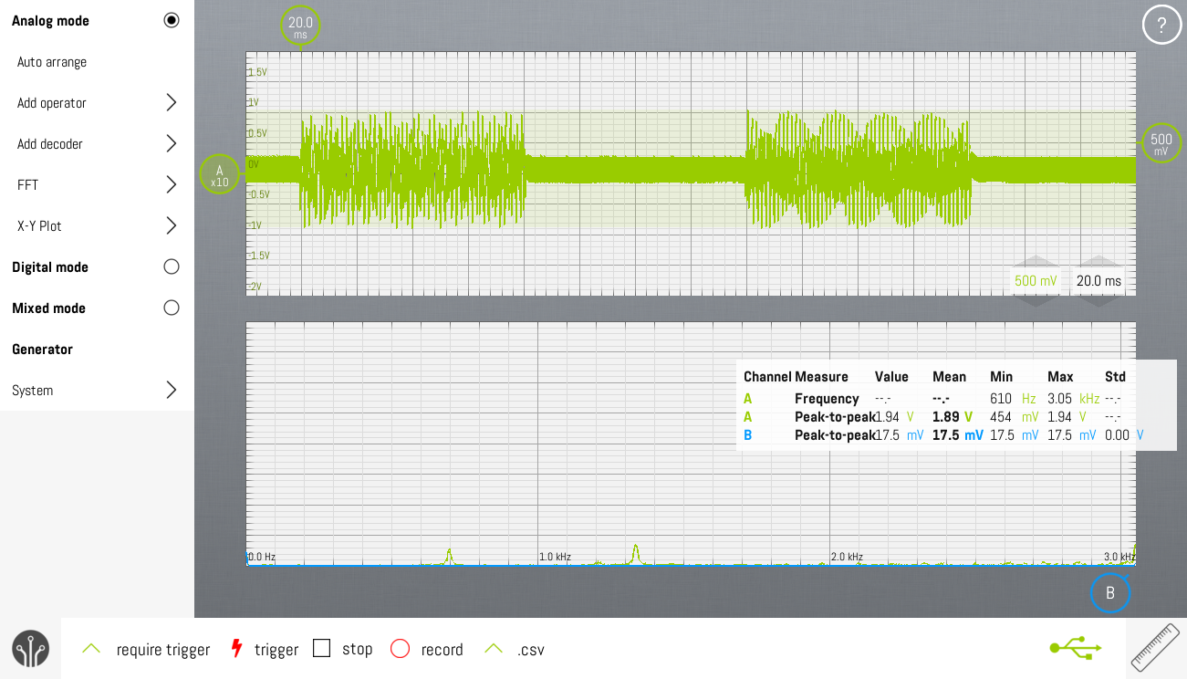
The measurements show the voltage at the audio output of the SLIC. As you can see, most of the HF-noise has been removed and there's no noticeable deformation of the DTMF-waveform.
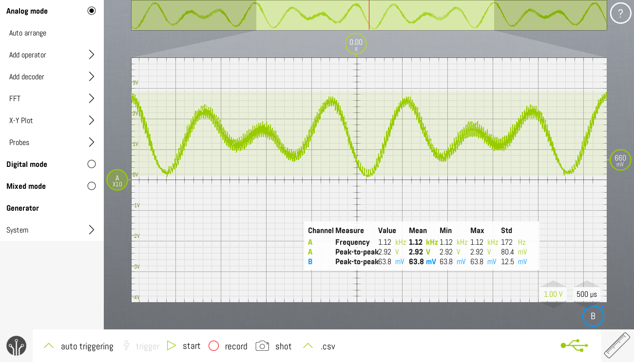
![]()
DTMF-pulse on SLIC's audio output ![]()
Zooming in on DTMF-signal on the SLIC's audio output
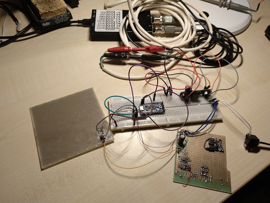
Picture of the current setupThere's not so much to see really. The breadboard contains the Adafruit Protrinket 3V and the SLIC. The 1.27mm-protoboard on the left has the opamp circuit on it. The 2.54mm-protoboard on the bottom right contains the TLV431 circuits. On the right, you can see the RJ11-connection to the telephone.
![]()
-
Direct Digital Synthesis
01/05/2018 at 21:07 • 0 commentsDTMF will be generated using Direct Digital Synthesis (DDS)
The first implementation will be done with Adafruit ProTrinket 3V, which runs at 12MHz. The final implementation will use some ATTiny at 8MHz.
DDS tuning equation where
- fo = output frequency
- M = phase accumulator
- fc = clock frequency
- n = bitwidth of phase accumulator
Frequency resolution
So the frequency resolution is :
The allowable frequency tolerance for the DTMF frequencies is ±1,5 %. This is maximum 10.4Hz for 697Hz, which is the lowest DTMF tone.
For 12MHz, fast PWM, the interrupt frequency is 47KHz, phase accumulator is 16-bit. The frequency resolution is (12MHz / 256) / 65536 = 0.7Hz. This is more than enough. Also for 8MHz system, the frequency resolution of the DDS is sufficient for this application.
Minimum clock frequency
There is also an upper limit to the frequency that can be generated. Practically:
For DTMF, the maximum frequency is 1633Hz, so fc, which is the frequency of the timer interrupt, should be at least 4.9KHz.
Comparison of PWM-modes for generating DDS
Below you can find two screenshots that show the difference between fast-PWM and phase-correct-PWM on the Adafruit ProTrinket 3V. Clearly, the phase correct PWM will need much more filtering to get a clean output signal. That's because the interrupt frequency in fast-PWM-mode is twice the interrupt frequency of the phase-correct-PWM mode.
The low pass filter used in all the screenshots is just a simple first order RC-filter: 330ohm with 100nF. These were just some parts lying around on my desk. The cutoff frequency is 4.8KHz.

697Hz DDS, 16bit tuning word, phase-correct PWM, 8bit sine table 
697Hz DDS, 16bit tuning word, fast-PWM, 8bit sine table Sine table
To avoid the time consuming operation of calculating a sine wave in real time, the values are precalculated and stored in flash.
The original implementation of which you can see screenshots above had a sine table with 256 values. To save space in flash, this has been reduced to 128 values. There's no noticeable difference in the output.
The pwm resolution of timer2 in the AVRMEGA is 8bit. The original sine table was normalized to 8bit, i.e. the sine values were in the range [0..255]. For application in DTMF, two sine waves must be added. The 8bit sine wave values will overflow. To prevent this, the sine table has been normalized to 7bit, i.e. [0..127].
Final output
![]()
Waveform of DDS output while generating '0' (941 + 1336 Hz) -
Measurements on commercial hardware
12/24/2017 at 19:31 • 0 commentsTest environment
As the design process will require measurements and manipulations on a potential high voltage telephone line, we can make it easy for ourselves by making a complete test setup on our test table. You probably don't want to destroy the SLIC in your VOIP Box, so we'll be using a separate SLIC-module.
The Silvertel AG1171 is a very simple to use SLIC-module. It might be hard to get as a hobbyist. The R-Tone KS0835F is fully compatible and available from the usual Chinese channels.
Modular jack RJ11
Info can be found on Wikipedia:
- pin 3 : RED : RING : -
- pin 4 : GREEN : TIP : +
So much for the standard, the Bbox2 VOIP-gateway uses reverse polarity.
Connecting the SLIC
For the KS0835F this becomes:
- pin 1 : RING = RJ11, pin 3
- pin 2 : TIP = RJ11, pin 4
- pin 3 : F/R = +5V ( reverse mode : ring positive with respect to tip). The drawing on the KS0835F datasheet is correct, the describing text is wrong.
- pin 4 : RM = GND (no ringing needed)
- pin 7 : VX = Audio out, decoupled with 220nF to oscilloscope to get rid of the 5VDC-offset
- pin 9 : GND
- pin 10 : +5VDC (100nF + 470µF close to pin 9&10 to get rid of the noise on pin 7). If you only supply with 3V3, the loop current will be considerably smaller, even to that agree that the ProTrinket3V refuses to boot.
Let's do some basic measurements first on this slic.
- On hook voltage : TIP=50V, RING=0V
- Off hook voltage
- 330ohm resistor : RING=16.7V, TIP=7.0V => 29mA loop current
- 220ohm resistor : RING=13.4V, TIP=7.0V => 29mA loop current
- Connecting resistor from RING to GND
- 220ohm resistor : RING=6.93V, TIP=0.1V => 31mA
- 330ohm resistor : RING=10.11V, TIP=0.1V => 32.6mA
- The RING-pin internally has a current source connected to it. The TIP-pin seems to have a 7V-zener like functionality.
- Ring-trip detection circuitry is built in on the RING-pin. Connecting a 3.8Kohm resistor causes the SHK-pin to come up (13mA?). There is some hysteresis to turn if off again.
Injecting audio in the SLIC
Differential mode input impedance
Our signal will be injected as a differential voltage to the SLIC. An audio transformer is used to converted the single ended test signal to a balanced signal. This signal is then AC-coupled to TIP-RING. By inserting an 22Kohm sense resistor, we can measure the input impedance of the SLIC. It appears to be close to 15Kohm. This impedance is constant to at least 22KHz.
Transresistance
The SLIC provides constant current to the load and measures the voltage over that load. The way to inject data is to modulate the load. The question is how much do we need to vary the load to get a certain output voltage?
Measurements have shown that a 30mA current change in the loop leads to a 1V change in the audio output.
Audio output
The audio output voltage is the simply the difference of the TIP and RING voltage, transferred to a 5VDC-offset.
Measuring DTMF signals of a Philips D200 DECT-base station
Let's see what COTS-devices output when they're generating DTMF-signals. In order to do that, we connect the Philips D200 DECT-base station to the SLIC's tip&ring. The oscilloscope is connected to the audio out of the SLIC.
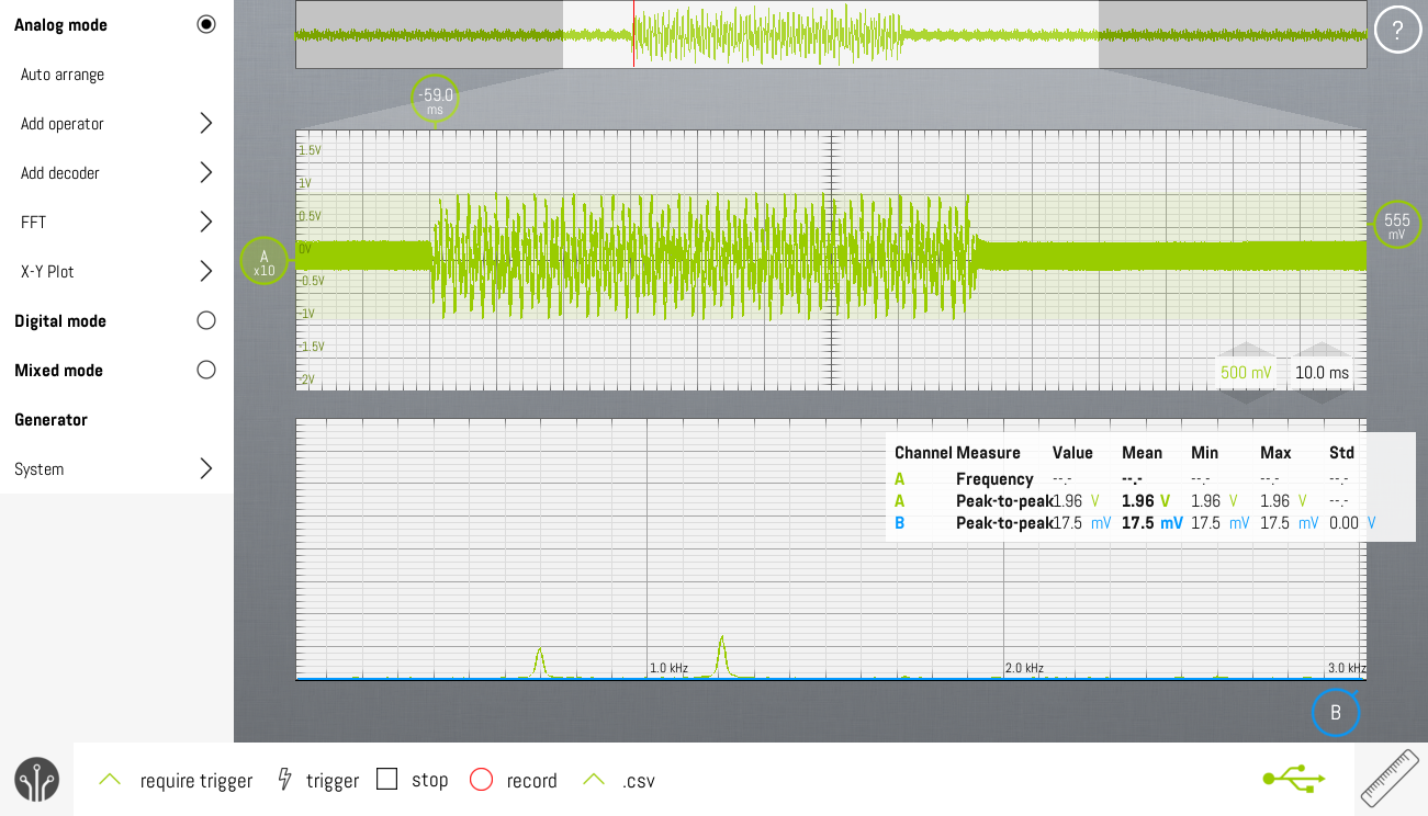
![]()
The screenshot shows a screen capture of the SLIC's audio out, while the Philips D200 is dialing "1". The FFT-shows energy on 700Hz (actually 697Hz) and 1200Hz (actually 1209Hz).
- Signal amplitude : 1.8Vpp
- Tone duration : 80ms
![]()
This screenshot is measured on the same signal. This time, the phone is dialing "12".
- Pause duration : 80ms
The SLIC audio conversion relative gain is 0dB, so it doesn't change the amplitude of the audio on the telephone line.
The Philips D200 generates it's DTMF which complies to the standard.
Bbox2 VOIP Box FXS-port measurements
Measurements done with POTS connected.
- On-hook voltage: 47.2V
- Off-hook voltage: 10.0V
-
Coupling audio to telephone line
12/23/2017 at 19:20 • 0 commentsThe trouble with telephone lines is they carry relatively small audio signals and high voltage ringing signals. If the circuitry is placed in parallel with the telephone line, it has to deal with the ringing voltage. At the same time, the circuit must be low-Z enough to inject audio signals.
The alternative option chosen here is to design circuitry that sits in series with the telephone line. The advantages are:
- No current consumption on hook.
- Easy way to feed electronics using a zener diode (only off-hook and in between DTMF-bursts).
- High ringing voltage is no longer an issue. The maximum voltage over the circuit is limited by the zener diode.
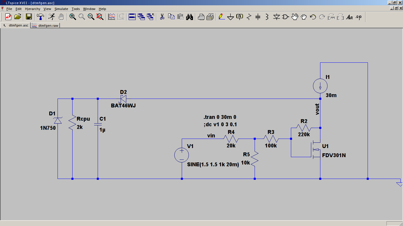
![]()
The SLIC provides a 30mA current loop, that's I1.
U1 is the variable load, modulated by the DTMF-source, U1. When the horn goes off-hook, the connected telephone closes the loop with a 300ohm resistor. The current through the loop will rise to 30mA. This causes the voltage over D1 to rise to 4.7V. The MCU will startup. U1 will start sinking considerable current. The rest of the current will be used to power the electronics. The DC-bias current through U1 can be set with R2 and R3. Check that during DTMF-transmitting, the output voltage (VOUT) doesn't exceed the zener voltage. The zener will limit the VOUT and distort the signal.
When transmitting DTMF, R4 and R5 set the amplitude of the DTMF-signal voltage on the current loop.
4.7nF caps will be added in parallel with R5 and to the base of U1 to filter the HF-noise of the PWM-output of the MCU.
Pulse to Tone Converter
Converts pulse dialing of your POTS telephone to DTMF dialing allowing you to use it with your VOIP's FXS-port.