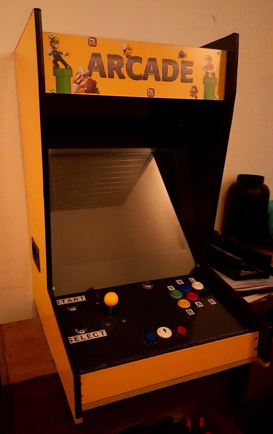
Arcade cabinet with Raspberry pi 2 B + Porta PI (RetroPie + Emulationstation).
The control panel is detachable and can be hooked up to any HDMI tv.
I designed the whole thing in Google SketchUp and made it out of 12mm MDF.
Inside the control panel is a Raspberry Pi B, an amplifier and a power cord which is connected to a switch on the outside. The pi, amplifier and screen are powered from that power cord.
The software will always be a work in progress, right now i have the following emulators running perfectly : SNES, NES, Gameboy Advance, Gameboy (Color) and Atari2600, other emulators work aswell but i don't want all of them.
I kept track of the costs and there's about 350 euro of materials in there, i spared no expense but tried to keep it as cheap as possible. Ultimatly it costs me a bit more since i made a few mistakes along the way.
Now that i have a good color printer, i finally decided to make a fancy new marquee image. I made the image in GIMP a while back, i tried to match the yellow of the arcade cabinet and it came out very nice.
I would like to light up the marquee, but it doesn't look good with printed photo-paper. For it to light up nicely i really need a high quality image on some kind of plastic i think, i'm not sure and i'm probably not gonna try.
I want some decals on the sides too, but i need to buy some good sticker paper for that. Will happen soon!
Here is a rough overview of what i did to get it al working, some steps are more detailed than others, i will try to share as much as i can.
1. Download the porta pi image (google it), this is a pre-configured pack of retropie and emulationstation and has a bunch of emulators installed.
2. Mount it on a SD card using Win32 Disk Imager.
3. Edit the GPIO mapping (See step 2).
4. Place your roms on a USB stick and transfer them to your Raspberry Pi and place them in the correct folders inside /home/pi/RetroPie/roms(for examle, place your GBA games inside /home/pi/RetroPie/roms/GBA).
5. For the GBA emulator to work you need to download a BIOS and place it on your pi, see step 3for detailed instructions.
6. Getting the startup splash screen to work (see step 4).
2
Step 2
Edit GPIO mapping :
1. Open retrogame config file :
CD /home/pi/Retrogame
sudo nano retrogame.c
2. Scroll down until you see the input array.
3. For a 1-player arcade machine you need to remove the player 2 inputs for it to work.
4. Edit the GPIO pin numbers for player 1 arcording to your wiring.
I am guessing that you had to cut some of the inner part of the 'T' mould to get it around those tight radius’s? or did flex enough? I was going to use 'T' mould at one stage but I didn't want to make the larger radius's that I expected it would need.
Exactly, i used a pair of nippers to cut out a V at the point where it bends. Be carefull when using an exacto knife instead of nippers, it"s quite easy to accedentally cut the whole thing in half. For large radius i would cut out multiple V's in a row.
What did you do for the edges of the MDF? I built one about 4 years ago but I didn't do anything for the edges and it looked awful.