 zakqwy
-
Making Izhikevich Neurons Fast on the STM32
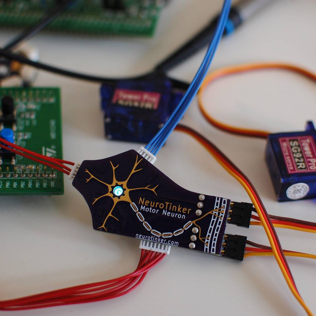
07/09/2017 at 05:29 • 1 commentMost of this post is going to be down in the embedded software nitty-gritty, but I think I'll start you off with a little video. Here's a neurobyte board on my bench emulating a "chattering" neuron:
Having written and verified an integer-based model of the neuron (as I've described in my previous post), I now need to check that it's still accurate on actual hardware and see that it can run at an acceptable speed. To do this, I split my code into a main loop, and a library that does all of the neuron work, then wrote a second main file to setup all of the hardware peripherals and run a timing loop on the microcontroller:
#include <libopencm3/stm32/rcc.h>
#include <libopencm3/stm32/gpio.h>

#include "./izhi.h"

#define FLOATPIN GPIO1
#define FIXEDPIN GPIO3

int main(void) {
    rcc_periph_clock_enable(RCC_GPIOA);
    rcc_periph_clock_enable(RCC_GPIOB);
    gpio_mode_setup(GPIOA, GPIO_MODE_OUTPUT, GPIO_PUPD_NONE, GPIO15);
    gpio_mode_setup(GPIOB, GPIO_MODE_OUTPUT, GPIO_PUPD_NONE, GPIO5);
    gpio_clear(GPIOA, GPIO15);
    gpio_clear(GPIOB, GPIO5);
    fneuron_t spiky_f;
    ineuron_t spiky_i;
    RS_f(&spiky_f);
    RS_i(&spiky_i);
    for (int i = 0; i < 5000; i++) {
        if (i < 100) {
            step_f(&spiky_f, 0, 0.1);
            step_i(&spiky_i, 0, 10);
        } else {
            gpio_set(GPIOA, GPIO15);
            step_f(&spiky_f, 10, 0.1);
            gpio_clear(GPIOA, GPIO15);

            gpio_set(GPIOB, GPIO5);
            step_i(&spiky_i, 10 * spiky_i.scale, 10);
            gpio_clear(GPIOB, GPIO5);
        }
    }
}
I also added a simple Makefile to keep track of the build details:
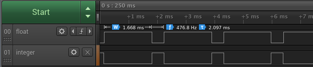
ARM_PREFIX = arm-none-eabi-
OPENCM3_DIR = ./libopencm3

CC = gcc
LD = gcc
RM = rm
OBJCOPY = objcopy

ARM_ARCH_FLAGS = -mthumb -mcpu=cortex-m0plus -msoft-float

ARM_CFLAGS = -I$(OPENCM3_DIR)/include -DSTM32L0 $(ARM_ARCH_FLAGS)
#ARM_CFLAGS += -fno-common -ffunction-sections -fdata-sections
ARM_LDLIBS = -lopencm3_stm32l0
ARM_LDSCRIPT = $(OPENCM3_DIR)/lib/stm32/l0/stm32l0xx8.ld
ARM_LDFLAGS = -L$(OPENCM3_DIR)/lib --static -nostartfiles -T$(ARM_LDSCRIPT)
ARM_LDFLAGS += $(ARM_ARCH_FLAGS)

host:
	$(CC) izhi.c host.c -o host.o

stm:
	$(ARM_PREFIX)$(CC) $(ARM_CFLAGS) -c izhi.c -o izhi.o
	$(ARM_PREFIX)$(CC) $(ARM_CFLAGS) -c stm.c -o stm.o
	$(ARM_PREFIX)$(LD) $(ARM_LDFLAGS) izhi.o stm.o $(ARM_LDLIBS) -o stm.elf
	$(ARM_PREFIX)$(OBJCOPY) -Obinary stm.elf stm.bin
	$(ARM_PREFIX)$(OBJCOPY) -Oihex stm.elf stm.hex

clean:
	$(RM) *.o *.elf *.map *.bin
With the code running on the native hardware, I fired up by trusty Saleae Logic analyzer to watch pins A15 and B5 to see the timing of my `step_f` and `step_i` loops, respectively.
![]()
![]()
It looks like the fixed-point implementation runs 4x faster at ~0.4ms per loop, vs. ~1.67ms for the floating-point version. This surprised me, I actually expected the floating-point one to be much much worse! As a quick check, I re-compiled with `typedef int16_t fixed_t;` to see if 16 bit integers gave any improvement (I expected not, but especially with performance issues it's important to test one's assumptions), and the integer runtime went down to about 0.32ms per `step_i` loop. Of course, the behaviour would be completely incorrect because of the integer overflow I was struggling with when trying to develop a 16bit version, but it's good to have the datapoint that it looks like a series of 16bit operations takes about 80% as long as a matching series of 32bit operations.
For completeness, I checked the two most obvious compiler optimization settings: `-Os` (optimize for size with speedups that tend not to increase size) and `-O3` (optimize for speed). These led to floating and fixed point loop times of 1.54ms/0.4ms and 1.6ms/0.37ms, so not really huge gains to be had there. This time I'm not surprised; the work being done is pretty straightforward and maps pretty easily to assembly code.
So how fast do I need to get going? Well Zach didn't exactly give me a spec to hit, but in his log on implementing this for v07 he says he needs to update the LEDs every 30us and has the model calculations broken up in to 7 steps of no more than 29us each (there's also steps for reading input dendrites, calculating the value I'm passing as `synapse`, and translating the neuron state into a colour value for the LEDs). To match this I'll aim for less than 200us to run through the neuron model.
The first improvement is the easiest: when the STM32L0 used on the board I have reboots, it starts up with a 2MHz internal clock, but the chip can run up to 16MHz (actually, 32MHz, but the board I have doesn't have an external oscillator, so I'm limited to 16MHz). When I switched over to that oscillator, the simple `step_i` loop went down to 52us (plus an additional 0.8us spent turning the pin I'm using for timing on and off). Oh well that's right inside the 200us I just mentioned, so the smart thing to do would be to try to split the code inside `step_i` into two or three parts of roughly equal runtime and call it a day. But I'm pretty sure there's some easy wins to be had so I'll just go for those.
To jog your memory, here's how the `step_i` call looks right now:
typedef int32_t fixed_t;
#define SQRT_FSCALE 1000
#define FSCALE (SQRT_FSCALE * SQRT_FSCALE)

typedef struct {
    // using 1/a, 1/b because a and b are small fractions
    fixed_t a_inv, b_inv, c, d;
    fixed_t potential, recovery;
} ineuron_t;

static void RS_i(ineuron_t *neuron) {
    neuron->a_inv = 50;
    neuron->b_inv = 5;
    neuron->c = -65 * FSCALE;
    neuron->d = 2 * FSCALE;
    neuron->potential = neuron->recovery = 0;
}

static void step_i(ineuron_t *neuron, fixed_t synapse, fixed_t fracms) {
    // step a neuron by 1/fracms milliseconds. synapse input must be scaled
    //  before being passed to this function.
    if (neuron->potential >= 30 * FSCALE) {
        neuron->potential = neuron->c;
        neuron->recovery += neuron->d;
        return;
    }
    fixed_t v = neuron->potential;
    fixed_t u = neuron->recovery;
    fixed_t partial = (v / SQRT_FSCALE) /  5;
    neuron->potential = v + (partial * partial + 5 * v  + 140 * FSCALE
                             - u + synapse) / fracms;
    neuron->recovery = u + ((v / neuron->b_inv - u) / neuron->a_inv) / fracms;
    return;
}
When Zach had to speed up the math on the AVR, he changed all the multiplications and divisons to use powers of two, so that he could just use shift operations. The STM32 has a one-cycle integer multiplier, so I'll start off by attacking division operations. The easiest one is the `/ fracms` that I use twice per loop to step the model by timesteps shorter than a millisecond. Instead of having the function work with arbitrary fractions of a millisecond, I've reworked it so that the fraction needs to be a power of two (it will step by 2**(-fracms) milliseconds), and just used a simple shift instead of the divide.
Just this change has brought me down to 37us per loop! This is almost down to being able to run the full model every time the LED timing needs to be updated, so I'm going to press harder still. Even though the datasheet claims this chip has a single-cycle multiplier, I'd feel better seeing proof of the fact. Yes, datasheets have lied to me in the past so I will fact-check them when it's easy to do so. An easy place to start is a multiplication by a constant, so I changed the `v * 5` component to `(v + (v << 2))`, and now this runs at 37.4us per loop, worse than before. I changed it back, and I'm not going to try to eliminate any more multiplications.
Looking for my next target, the divisions by `neuron->a_inv` and `neuron->b_inv` would be hard to turn into shift operations (or even groups of shifts and adds) because they are elements of the model and I will want to keep the model as general as I can support. This leaves me the calculation of `partial` to work on.
`FSCALE` is completely implementation-dependent, and `1000` is conveniently close to `1024 == (2 ** 10)`. So changing `SQRT_FSCALE` to 1024 and replacing `(v / SQRT_FSCALE)` with `(v >> 10)` bought me... exactly no improvement. It doesn't seem right to me that I'd get 15us of speedup by removing two divides, and then no further speedup by removing a third, so I wanted to see what was happening. I added debug listings to the compiler output with the `-g` flag, and then re-compiled the original (two divides to calculate `partial`) and got an assembly listing (with the command `arm-none-eabi-objdump -S stm.hex > stm.list`) to see what the compiler was up to.
Here's the decompiled assembly for the calculation of partial:
    fixed_t partial = (v / SQRT_FSCALE) / 5;
 80002f8:   69fa        ldr r2, [r7, #28]
 80002fa:   23a0        movs    r3, #160    ; 0xa0
 80002fc:   0159        lsls    r1, r3, #5
 80002fe:   0010        movs    r0, r2
 8000300:   f000 fb86   bl  8000a10 <__aeabi_idiv>
 8000304:   0003        movs    r3, r0
 8000306:   617b        str r3, [r7, #20]
Oh, clever compiler: there's only one division (the branch at location 8000300) there. gcc recognized that I was dividing by a known constant (`SQRT_FSCALE`) and then again by another known constant (5), and combined them into a single division call to help me out. I didn't get a speedup by eliminating one of the division operations because the compiler had already gotten this calculation down to one division for me. Oh well, I guess I'll just try harder...
My next gut reaction was to add up order-of-two fractions to approximate 1/5 (eg. 1/8 + 1/16 + 1/128 + 1/256 is 0.19921875, and that's pretty close), but that started to look like a lot of partial fractions to make up the precision. Instead, I figured I could do something like
#define LOG_SQRT_FSCALE 10
#define SQRT_FSCALE (1 << LOG_SQRT_FSCALE)
fixed_t partial = ((v >> LOG_SQRT_FSCALE) * x) >> y;
where I would pick `x` and `y` to approximate overall dividing by 5. I want to make it easy to ensure I don't run into integer overflow problems again, so I'll keep `x` below `SQRT_FSCALE`:// 1024 * 5 = 5120 // log2(5120) = 12.322 (use 2**12 == 4096) // 4096 / 5 = 819.2 (use 819) fixed_t partial = ((v >> LOG_SQRT_FSCALE) * 819) >> 12;The error from replacing "divide by 5" with "multiply by 819 then divide by 4096" is about 244 parts per million, and I'm okay with that.Once again, I recompiled and ran the code and it got down to 30.2us per loop. Inspired by seeing the compiler combine divisors into one division call, I pulled `neuron->b_inv` out a level and cut down the work of calculating `neuron->recovery` to a single division, and got a huge improvement, with per-loop timing down to 17.8us! I don't know why that lopped over 12us off the loop timing when previously removing a divide would only shave 7us, but I'll take it.
//neuron->recovery = u + (((v / neuron->b_inv - u) / neuron->a_inv)
//                        >> fracms);
neuron->recovery = u + (((v - u * neuron->b_inv)
                         / (neuron->b_inv * neuron->a_inv)) >> fracms);
I'm happy with where that stands for now, removing the final division is not impossible (my first attempt would be a pre-multiply and shift-right strategy like I did when calculating `partial`) but I think it would add too much complexity when setting up the neuron properties. Just to check and see how fast getting rid of the last division would be, I did a timing run with it replaced by a hard-coded right shift and it was down to 7.2us per loop. At least I know that speed is available if I want it and want to work for it.
The last thing to do is implement constructors for the other neuron types and then compare them to floating-point implementations. The actual calculations should not be affected by the performance improvements, but it'll be good to check to make sure. To do this I created a simple gnuplot script named neuroncheck.p:
set term png size 1280,960
set output 'tmp/rs.png'
set title "RS neuron"
plot 'neurons.dat' using 1:2 title 'float' with lines, 'neurons.dat' using 1:3 title 'fixed' with lines

set output 'tmp/ib.png'
set title "IB neuron"
plot 'neurons.dat' using 1:4 title 'float' with lines, 'neurons.dat' using 1:5 title 'fixed' with lines

set output 'tmp/ch.png'
set title "CH neuron"
plot 'neurons.dat' using 1:6 title 'float' with lines, 'neurons.dat' using 1:7 title 'fixed' with lines

set output 'tmp/fs.png'
set title "FS neuron"
plot 'neurons.dat' using 1:8 title 'float' with lines, 'neurons.dat' using 1:9 title 'fixed' with lines

set output 'tmp/lts.png'
set title "LTS neuron"
plot 'neurons.dat' using 1:10 title 'float' with lines, 'neurons.dat' using 1:11 title 'fixed' with lines

set output 'tmp/rz.png'
set title "RZ neuron"
plot 'neurons.dat' using 1:12 title 'float' with lines, 'neurons.dat' using 1:13 title 'fixed' with lines

set output 'tmp/tc.png'
set title "TC neuron"
plot 'neurons.dat' using 1:14 title 'float' with lines, 'neurons.dat' using 1:15 title 'fixed' with lines
and when checking through visually it mostly looks alright:
- Most neuron outputs look like they do in the paper, and the fixed and floating point implementations don't differ by much
- The fixed point implementation looks a little slower (the neuron's reaction speed, this isn't about processing speed) than the floating point one, but not horribly so.
- My IB implementations don't agree with each other, and neither agrees with what was presented in the paper.
- My RZ implementations agree with each other, but are always firing, unlike the RZ in the paper.
The end result here is a little mixed: The obvious way to implement this model (using floating point) would have taken about 210us per loop, and I've got it down to 7.2us per loop without too drastically affecting the readability of the code. This may seem like overkill (if it only needs to update every 200us, why bother?) but this frees up a lot of space to do other things like run complex sensors, calculate spiffy lighting, or even run multiple neurons on one microcontroller. On the flip side, I'm not sure why my IB and RZ neurons aren't doing well, and this is going to require me to dig back into the paper to understand what's really going on.
Here's the final code, I expect it to roll into the main repo soon, but you can also see my work on its own, frozen in time on my github page.
// XXX Note: if you change LOG_SQRT_FSCALE, you'll need to re-check the math // XXX to confirm that it won't overflow, as well as play with those // XXX constants when calculating `partial`. #define LOG_SQRT_FSCALE 10 #define SQRT_FSCALE (1 << LOG_SQRT_FSCALE) #define FSCALE (SQRT_FSCALE * SQRT_FSCALE) static void base_i(ineuron_t *neuron) { neuron->a_inv = 50; neuron->b_inv = 5; neuron->c = -65 * FSCALE; neuron->d = 2 * FSCALE; neuron->potential = neuron->recovery = 0; neuron->scale = FSCALE; } void RS_i(ineuron_t *neuron) { base_i(neuron); neuron->d = 8 * FSCALE; } void IB_i(ineuron_t *neuron) { base_i(neuron); neuron->c = -55 * FSCALE; neuron->d = 4; } void CH_i(ineuron_t *neuron) { base_i(neuron); neuron->c = -50 * FSCALE; } void FS_i(ineuron_t *neuron) { base_i(neuron); neuron->a_inv = 10; } void LTS_i(ineuron_t *neuron) { base_i(neuron); neuron->b_inv = 4; } void RZ_i(ineuron_t *neuron) { base_i(neuron); neuron->a_inv = 10; neuron->b_inv = 4; // should be 1/0.26, we'll see if this is close enough } void TC_i(ineuron_t *neuron) { base_i(neuron); neuron->d = FSCALE / 20; neuron->b_inv = 4; } void step_i(ineuron_t *neuron, fixed_t synapse, uint8_t fracms) { // step a neuron by 2**(-fracms) milliseconds. synapse input must be scaled // before being passed to this function. if (neuron->potential >= 30 * FSCALE) { neuron->potential = neuron->c; neuron->recovery += neuron->d; return; } fixed_t v = neuron->potential; fixed_t u = neuron->recovery; //fixed_t partial = (v / SQRT_FSCALE) / 5; fixed_t partial = ((v >> LOG_SQRT_FSCALE) * 819) >> 12; neuron->potential = v + ((partial * partial + 5 * v + 140 * FSCALE - u + synapse) >> fracms); //neuron->recovery = u + (((v / neuron->b_inv - u) / neuron->a_inv) // >> fracms); neuron->recovery = u + (((v - u * neuron->b_inv) / (neuron->b_inv * neuron->a_inv)) >> fracms); return; } -
Porting the Izhikevich Behaviour to the STM32
06/17/2017 at 21:18 • 1 commentAs Zach teased on the touch slider update, there's been work happening behind the scenes to implement the Izhikevich neuron model on the newer NeuroBytes boards. Well I may as well introduce myself (hi, I'm Patrick! In the daytime I'm an Electrical Engineer, and have been attracted to help out the project here because it reminds me of Valentino Braitenberg's Vehicles, a book that helped kick-start my interest in robotics) and I figured I would keep a log during my work for any budding programmers who would want a peek into the work of an embedded software engineer.
Straight from the source, we have a model of the neuron where
v' = 0.04v**2 + 5v + 140 - u + I
u' = a(bv - u)
if v >= 30, then {v = c, u = u + d}
which I implemented in C on my host machine as
#include <stdint.h>
#include <stdio.h>

typedef float float_t;

typedef struct {
    float_t a, b, c, d;
    float_t potential, recovery;
} fneuron_t;

static void RS(fneuron_t *neuron) {
    // create a "regular spiking" floating point neuron
    neuron->a = 0.02;
    neuron->b = 0.2;
    neuron->c = -65;
    neuron->d = 2;
    neuron->potential = neuron->recovery = 0;
}

static void step_f(fneuron_t *neuron, float_t synapse, float_t ms) {
    // step a neuron through ms milliseconds with synapse input
    //   if you don't have a good reason to do otherwise, keep ms between 0.1
    //   and 1.0
    if (neuron->potential >= 30) {
        neuron->potential = neuron->c;
        neuron->recovery += neuron->d;
        return;
    }
    float_t v = neuron->potential;
    float_t u = neuron->recovery;
    neuron->potential = v + ms * (0.04 * v * v + 5 * v + 140 - u + synapse);
    neuron->recovery = u + ms * (neuron->a * (neuron->b * v - u));
    return;
}

int main(void) {
    fneuron_t spiky;
    RS(&spiky);
    for (int i = 0; i < 2000; i++) {
        if (i < 100) {
            step_f(&spiky, 0, 0.1);
        } else {
            step_f(&spiky, 10, 0.1);
        }
        printf("%f %f\n", i * 0.1, spiky.potential);
    }
}
I compile and run this with
gcc izhi.c -o izhi
./izhi > rs.dat
I use gnuplot to display this quickly, by starting it up and using the command
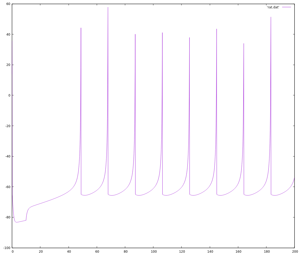
plot 'rs.dat' with lines
The output looks more or less like the outputs from the paper, at least to my eye.![]()
The next step was to implement the easiest fixed-point version I can think of, to see how well its output aligns with the floating-point version. The reason to do this is that floats mask a lot of complexity (their dynamic range protects me from rounding errors, overflow, and underflow, for example) that will become my problem to deal with when I work with fixed point arithmetic. Here is the added fixed-point math and an updated main function:
typedef int16_t fixed_t;
#define FSCALE 320

typedef struct {
    // using 1/a, 1/b because a and b are small fractions
    fixed_t a_inv, b_inv, c, d;
    fixed_t potential, recovery;
} ineuron_t;

static void RS_i(ineuron_t *neuron) {
    neuron->a_inv = 50;
    neuron->b_inv = 5;
    neuron->c = -65 * FSCALE;
    neuron->d = 2 * FSCALE;
    neuron->potential = neuron->recovery = 0;
}

static void step_i(ineuron_t *neuron, fixed_t synapse, fixed_t fracms) {
    // step a neuron by 1/fracms milliseconds. synapse input must be scaled
    //  before being passed to this function.
    if (neuron->potential >= 30 * FSCALE) {
        neuron->potential = neuron->c;
        neuron->recovery += neuron->d;
        return;
    }
    fixed_t v = neuron->potential;
    fixed_t u = neuron->recovery;
    neuron->potential = v + ((v * v) / FSCALE / 25 + 5 * v
                             + 140 * FSCALE - u + synapse) / fracms;
    neuron->recovery = u + ((v / neuron->b_inv - u) / neuron->a_inv) / fracms;
    return;
}

int main(void) {
    fneuron_t spiky_f;
    ineuron_t spiky_i;
    RS_f(&spiky_f);
    RS_i(&spiky_i);
    for (int i = 0; i < 5000; i++) {
        if (i < 100) {
            step_f(&spiky_f, 0, 0.1);
            step_i(&spiky_i, 0, 10);
        } else {
            step_f(&spiky_f, 10, 0.1);
            step_i(&spiky_i, 10 * FSCALE, 10);
        }
        printf("%f %f %f\n", i * 0.1, spiky_f.potential,
               (float_t)(spiky_i.potential) / FSCALE);
    }
}
I'd like to highlight a few habits that usually make my life easier:
typedef int16_t fixed_t;
#define FSCALE 320
I took an initial guess that I'd be using 16-bit ints (this eventually will target a 32bit processor, but Zach's earlier work was happily using 16 bits, so I'm starting there), but if I change my mind later I don't want to track down every place that I declared an int16_t and change it to an int32_t. That's setting myself up for a mistake and a frustrating bug, so I use the typedef to "create" a new type, aliased to int16_t, that I can use all over and only need to change one line to switch it all to a different size.
Similarly, I #define'd the scaling factor right there as well. This number is equivalent to 1.0 in the floating point implementation, and again if I find my scaling is wrong, I can just change it in this one place instead of tracking down every usage. I chose 320 because a 16bit signed int goes from -2^15 to +2^15, or roughly speaking -32000 to +32000, and the neuron potential and recovery values stay comfortably within the -100 to +100 range. There's definitely value in analyzing this decision more thoroughly; if I'm too cautious then I'm losing precision by never exercising the full range, but if I'm not cautious enough I risk overflowing the variable size and "wrapping around" from larger than the largest possible positive value to a very large negative value, or vice-versa.
Lastly, I kept the floating point implementation around so that I can run my new fixed point version against the same inputs and compare the two side-by-side to make it easier to spot any differences in behaviour. And it's a good thing I did, because if I build and run this version and examine the output,
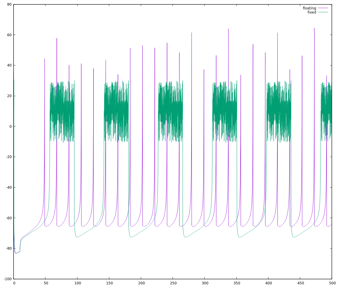
gcc izhi.c -o izhi && ./izhi >rs.dat && gnuplot
gnuplot> plot 'rs.dat' using 1:2 title 'floating' with lines, \
              'rs.dat' using 1:3 title 'fixed' with lines
I get this:
![]()
If I weren't comparing the two on the same plot, I'd be tempted to say they're basically the same. Side-by-side though, we can immediately see that one is running slightly faster than the other. If we count the spikes starting with the nearly-coincident ones near t=200 until the next nearly-coincident ones (roughly t = 375), there are 10 floating point spikes vs. 9 fixed point spikes. The fixed point implementation is rising approximately 90% as fast as the floating point implementation I'm considering my reference.
This is why I started with the simplest attempt I thought would work. If I saw this mis-alignment with a more clever attempt, I'd start asking myself where my cleverness let me down and I'd have many more dark corners to go looking in. As it stands, it's fairly simple to look through the code and see if I missed something. There's maybe a half-dozen places to make sure I did the (a*x -> x/(1/a)) conversion properly, and I can convince myself that I did it right.
It looked like I had converted the numbers properly, so I started looking for another explanation, something specific to how I was doing the fixed point math. The fixed point neuron seems to rise a little bit slower than the floating point one, so I thought maybe I had a small error in my math that on any one step would be inconsequential, but over hundreds of steps would add up.
When you divide integers in C, the computer doesn't necessarily round the result up or down to the nearest integer, it will just truncate it and throw away the lost precision. This means that every number between 50 and 59, when divided by 10, will return 5. This is one way to have a constant bias on your results, and the way I know to deal with this is to add half of your divisor to the numerator before doing the division. (50 + 5)/10 = 5, (54 + 5)/10 = 5, but (55 + 5)/10 = 6.
I tried applying this trick, and it didn't really help. In fact, as a first step I split out `((v * v) / FSCALE / 25 + 5 * v + 140 * FSCALE - u + synapse)` into a partial result, and the whole calculation went sideways and `neuron->potential` would just oscillate really quickly in between -20 and 0. I think the math in that equation was all being done in 32 (or 64) bit integers that are the native type on my computer and only being re-cast to 16 bits at the end. Forcing the partial result in to a 16 bit int exposed an integer overflow that wasn't obvious otherwise.
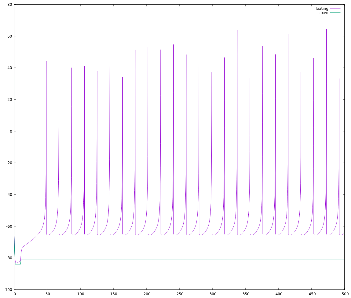
Checking this guess was pretty easy, I changed to `typedef int32_t fixed_t;` and the result was back to well-behaved spikes (but still activating at a slower-then-expected rate). Okay sure, my guess of `#define FSCALE 320` must have been a little too high, so I cut it down a bit and ran with
typedef int16_t fixed_t;
#define FSCALE 160
Aaaand... oh dear. That hasn't exactly helped.
![]()
It seems I was just lucky with my first choice for scaling, and there's actually a lot of choices that would not work (reducing the scale should be safe, so long as the lost precision doesn't destroy the behaviour). It's time to stop shooting from the hip on this one, and go back to proper analysis.
My initial thought on the scaling was that the neuron potential stayed well within the -100..100 range, so I could safely use that as my min and max values. Looking at the equations as I've written them out, that's clearly wrong for partial results. Just starting with the squaring term and substituting our assumed max for v:
v * v => (100 * FSCALE) * (100 * FSCALE)
      => 10000 * FSCALE * FSCALE
Whoops. Even if we were to restrict v to 30, we'd be at (900 * FSCALE**2), well past our assumed max of 100, and I already know that's not an assumption I can make, because v actually resets all the way down at -65. Luckily, we can re-order the operations: the next thing I do with this squared result is divide it, so I can keep everything more in check by distributing that division inside the squaring.
partial = (v * v) / FSCALE / 25
becomes
partial = ((v / (SQRT_FSCALE * 5)) * (v / (SQRT_FSCALE * 5)))
where `SQRT_FSCALE` is the square root of `FSCALE`. Checking now to see how likely it is we overflow by calculating the first part of that partial while substituting 100 for v:
((100 * FSCALE) / (SQRT_FSCALE * 5))
 ==> ((100 / 5) * (FSCALE / SQRT_FSCALE))
 ==> (20 * SQRT_FSCALE)
and we can see that squaring that term will give us a max value of `partial = 400 * FSCALE`. Much more reasonable.
Of course, the next two terms we add are `5 * v + 140 * FSCALE`, which would max out at `5 * (100 * FSCALE) + 140 * FSCALE == 640 * FSCALE`.
Turning our attention to the neuron recovery variable, u, even with ridiculously large values of v = 100 and u = -100, the step size is 2.2, so I don't see it contributing much (`2.2 * FSCALE` that is) here. Similarly, for now the value of `synapse` I'm using is `10 * FSCALE`, so combined they are on the order of 1% the max contribution of the first three terms.
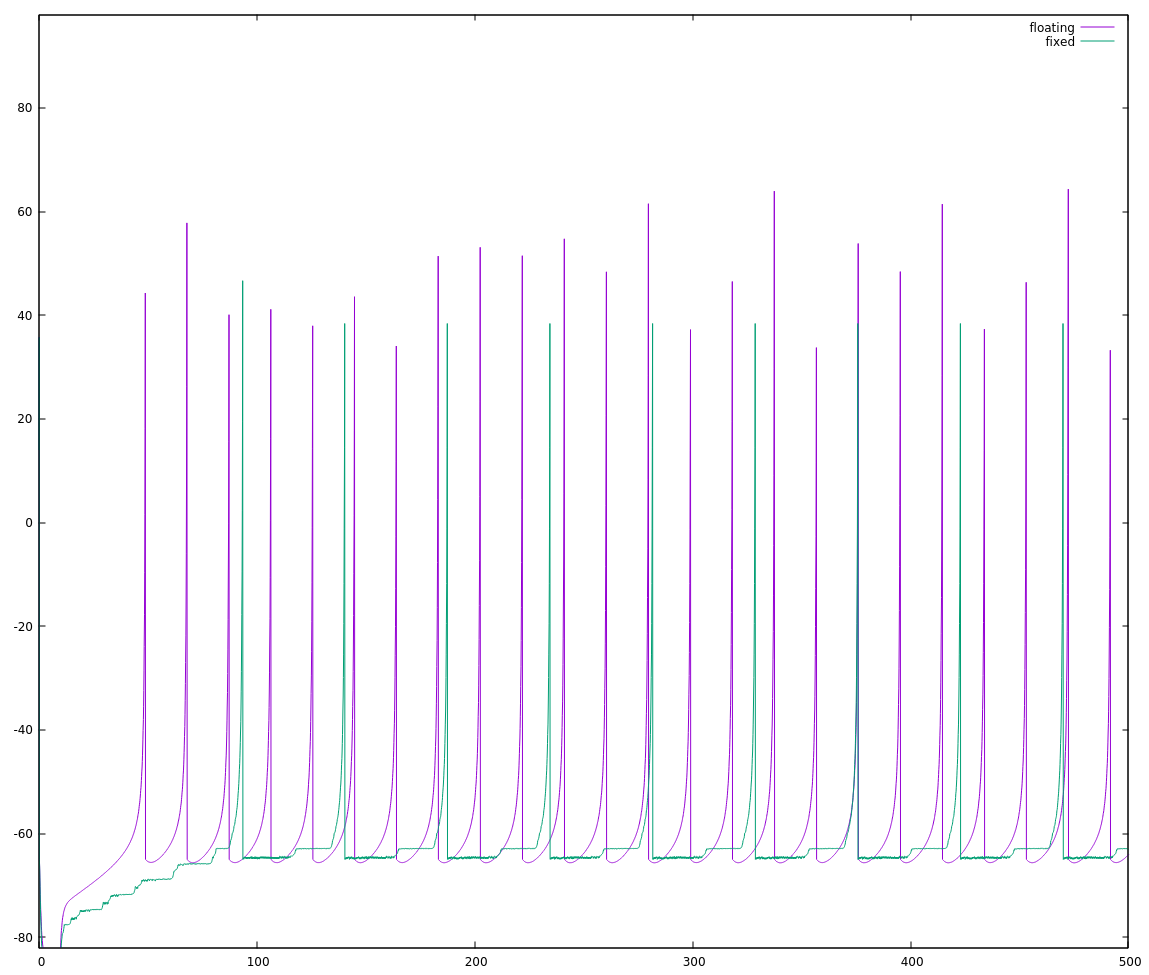
So I can choose `FSCALE` as roughly `INT_MAX / 1100` and try again. This could be 29.789, but I need to round down (integers!) to 29, and then there's an additional restriction that I need `SQRT_FSCALE` as well, so may as well cut back to `FSCALE = 25; SQRT_FSCALE = 5;`. Trying that, I get:
![]()
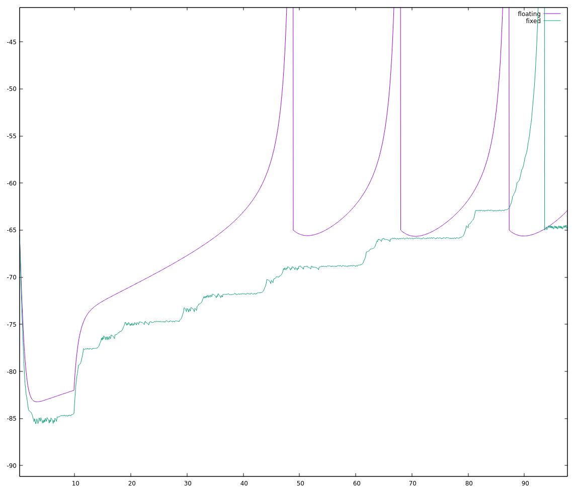
Okay, not exactly stellar either. Zooming in to the start of this run:
![]()
the fixed point implementation looks "choppy", which seems typical of too little precision to me.
I've broken out the calculation for neuron potential as
// neuron->potential = v + ((v * v) / FSCALE / 25 + 5 * v
//                          + 140 * FSCALE - u + synapse) / fracms;
fixed_t partial = ((v / (SQRT_FSCALE * 5)) * (v / (SQRT_FSCALE * 5)));
neuron->potential = v + (partial + 5 * v + 140 * FSCALE - u + synapse) / fracms;
and if I want to bring down the max value of sub-calculations of the potential, I need to reduce the size of the partial, 5*v, and 140*FSCALE terms. Luckily, they're all divided by fracms, which I can just distribute inside the parentheses. Unfortunately, partial is already pretty large and needs to be stored somewhere as a fixed_t, so the best approach seems to be either I apply the divisor to only one of the subpartials (and suffer a loss of precision), or I need a divisor I can break in to two terms and apply to each. For now, I'm going to lock down a fracms of 10, and see how that shakes out. This is a hit on the flexibility of the step_i() function, but we need to get it working correctly first.
fixed_t subpartial = v / (SQRT_FSCALE * 5);
fixed_t partial = ((subpartial / 5) * (subpartial / 2) + v / 2
                   + 14 * FSCALE) + (synapse - u) / 10;
neuron->potential = v + partial;
Now partial will be on the order of
(400 * FSCALE / 10) + 100 * FSCALE / 2 + 14 * FSCALE == 104 * FSCALE
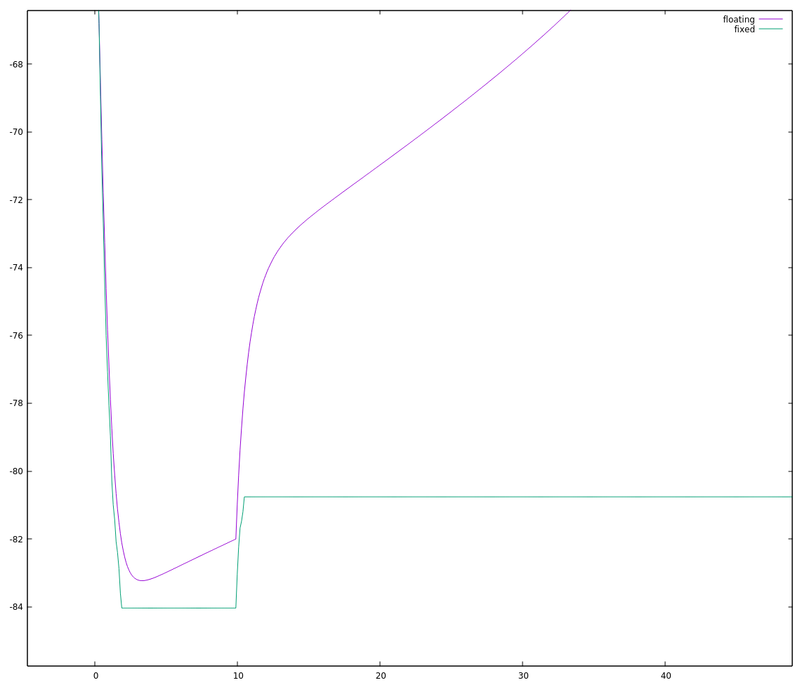
actually much closer to our original (100 * FSCALE) limit. Choosing a value for FSCALE using 32768/104 = 315.077, the nearest perfect square without going over is 289 (17**2). This gave a more promising, but not perfect waveform:
![]()
Actually, zooming in I can see distinct steps in the neuron potential which makes me suspect a loss of precision:
![]()
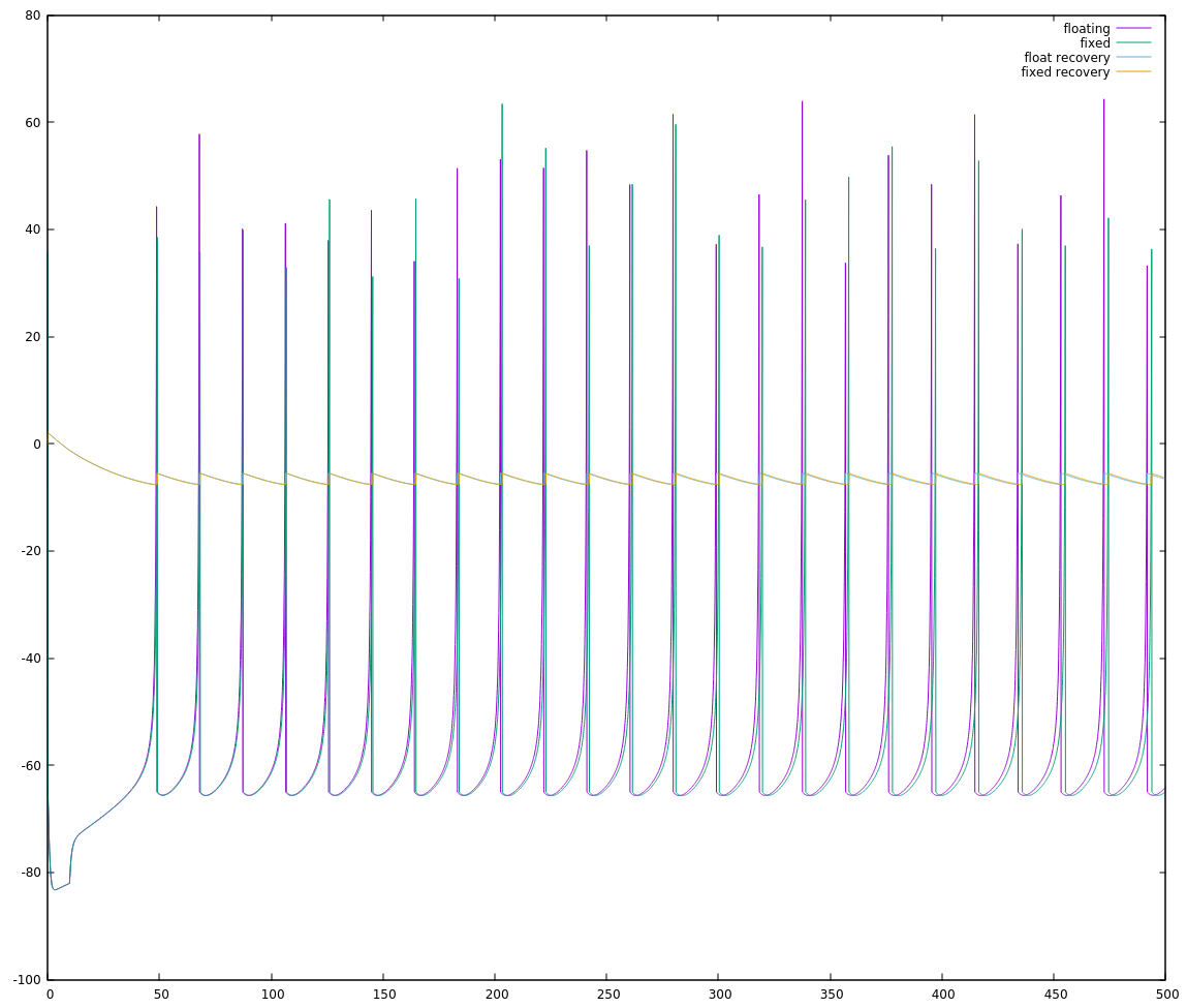
and plotting out the value of `neuron->recovery` shows I very distinctive break from the floating point behaviour:
![]()
I looked at a few different choices for FSCALE and juggled the distribution of divisors around a little bit, and I suspect that 16 bit signed ints are just a little shy of the dynamic range needed to implement this algorithm in a straightforward manner. So I'm going to do something I should've done a long time ago: I'll move to 32 bit ints.
INT_MAX on an int32_t is roughly 2 billion, so we'll set a conservative FSCALE of 1 million. Yes, that made things much much easier:
![]() The final code at this point, working with 32bit ints on my personal computer follows. In my next log, I'll go through what it took me to get this running on my NeuroByte board and then how to get it running more quickly.
The final code at this point, working with 32bit ints on my personal computer follows. In my next log, I'll go through what it took me to get this running on my NeuroByte board and then how to get it running more quickly.#include <stdint.h> #include <stdio.h> typedef float float_t; typedef struct { float_t a, b, c, d; float_t potential, recovery; } fneuron_t; static void RS_f(fneuron_t *neuron) { // create a "regular spiking" floating point neuron neuron->a = 0.02; neuron->b = 0.2; neuron->c = -65; neuron->d = 2; neuron->potential = neuron->recovery = 0; } static void step_f(fneuron_t *neuron, float_t synapse, float_t ms) { // step a neuron through ms milliseconds with synapse input // if you don't have a good reason to do otherwise, keep ms between 0.1 // and 1.0 if (neuron->potential >= 30) { neuron->potential = neuron->c; neuron->recovery += neuron->d; return; } float_t v = neuron->potential; float_t u = neuron->recovery; neuron->potential = v + ms * (0.04 * v * v + 5 * v + 140 - u + synapse); neuron->recovery = u + ms * (neuron->a * (neuron->b * v - u)); return; } typedef int32_t fixed_t; #define SQRT_FSCALE 1000 #define FSCALE (SQRT_FSCALE * SQRT_FSCALE) typedef struct { // using 1/a, 1/b because a and b are small fractions fixed_t a_inv, b_inv, c, d; fixed_t potential, recovery; } ineuron_t; static void RS_i(ineuron_t *neuron) { neuron->a_inv = 50; neuron->b_inv = 5; neuron->c = -65 * FSCALE; neuron->d = 2 * FSCALE; neuron->potential = neuron->recovery = 0; } static void step_i(ineuron_t *neuron, fixed_t synapse, fixed_t fracms) { // step a neuron by 1/fracms milliseconds. synapse input must be scaled // before being passed to this function. if (neuron->potential >= 30 * FSCALE) { neuron->potential = neuron->c; neuron->recovery += neuron->d; return; } fixed_t v = neuron->potential; fixed_t u = neuron->recovery; fixed_t partial = (v / SQRT_FSCALE) / 5; neuron->potential = v + (partial * partial + 5 * v + 140 * FSCALE - u + synapse) / fracms; neuron->recovery = u + ((v / neuron->b_inv - u) / neuron->a_inv) / fracms; return; } int main(void) { fneuron_t spiky_f; ineuron_t spiky_i; RS_f(&spiky_f); RS_i(&spiky_i); for (int i = 0; i < 5000; i++) { if (i < 100) { step_f(&spiky_f, 0, 0.1); step_i(&spiky_i, 0, 10); } else { step_f(&spiky_f, 10, 0.1); step_i(&spiky_i, 10 * FSCALE, 10); } printf("%f %f %f %f %f\n", i * 0.1, spiky_f.potential, (float_t)(spiky_i.potential) / FSCALE, spiky_f.recovery, (float_t)(spiky_i.recovery) / FSCALE); } }PS: If I were doing this work professionally, I would have been expected to try the 32bit integers first. The chip this is eventually targetting is a 32bit core, and can do 32bit multiplication in a single clock cycle. Even if it couldn't, I should be trying the easy thing first, and only spending my time optimizing some code if I can show it actually needs to be faster. It's often the case that code runs much differently than one expects, especially on an architecture one isn't intimately familiar with.
Even so, I've got more ideas for a 16bit version, so I may just come back to it later.
-
Free (well, PCB-track-only) Touch Sliders!
05/23/2017 at 20:42 • 0 commentsOne of the many NeuroBytes boards we are currently developing is the Tonic Neuron. This board is sometimes referred to as the Izhikevich Neuron due to the origin of its algorithmic inspiration (and ensuing porting effort, first detailed here and here and continuing elsewhere, which is a discussion for another log post...). The Tonic Neuron is useful because it fires spontaneously, allowing the user to inject periodic signals into a larger NeuroBytes network. In addition to modelling actual tonic neurons in the body, these boards provide a compact (compared to ring oscillators) 'pacemaker' for robotics experiments such as the NeuroBuggy and the Invertebrate Locomotion Model.
In an effort to reduce the BOM price, assembly steps, physical size, and general clunkiness of a potentiometer-based board, I spun up an experimental PCB to examine the possibility of using a linear touch slider as the user input for varying the Tonic Neuron's pulse rate:
![]()
The slider itself is roughly 20mm long, and connects to a pair of GPIOs on the STM32L. Otherwise, the pins float entirely -- even the ground plane is separated by 2mm and constructed of a low-density grid, all in an effort to reduce parasitic capacitance to ground. When a user touches one of the pads, the capacitance to ground increases; since this effect is related to the contact area on the pad, using the triangular design shown above means the capacitance increase varies linearly as the user swipes their finger along the control. I should mention here that the design of these pads (and the underlying concept generally) can be found in many places, including ST's Touch Sense Design Guide. Other manufacturers have similar white papers; just keep in mind that they're usually written around a touch sensing peripheral, which my cheap-o-edition chips certainly do not include. It's okay, we don't need a fancy peripheral to handle touch input, especially if we aren't putting a barrier in front of the PCB itself:
We are dealing with quite low capacitance here, to the point that connecting my 15 pF oscilloscope probes to de-tented vias dramatically changes the circuit's response. Measuring this change with the microcontroller is actually quite simple, and is explained nicely on the Arduino implementation website. Rather than using the unrolled loop method described in that code, I made use of the TIM21 input capture peripheral as follows:
- Set Touch Sensor 0 as an input and activate the pulldown resistor.
- Start TIM21 at clock speed and tell it to stop counting when the Touch Sensor 0 pin goes high.
- Activate the Touch Sensor 0 pullup resistor.
- Wait a few cycles to ensure that the pin went high.
- Record the TIM21 counter value.
- Repeat steps 1-5 for Touch Sensor 1.
- The touched location on the strip will be proportional to the difference between the two counter values, zeroed in the center.
In practice, and with the pullup values and parasitic/body capacitance my setup produces, I found that the total time differential to be around 1.5 microseconds. At the current (relatively low) processor clock rate, that gives me ~3 bits of position resolution which should be more than adequate for our purposes. I suspect adding external components (particularly larger pullups/pulldowns triggered by other GPIOs) could increase the time differential a bit and allow one to eek out more resolution without a faster clock, but that would require more BOM lines!
The code is here if you'd like to take a gander or use it in your own project (GPL v3); we're using libopencm3 along with a few hacks to get the TIM21 peripheral up, which we'll PR to the main project at some point once we have the library updated. All of the touch slider stuff is pretty well self-contained in main.c under the functions get_touch() and get_slider_position().
-
Cochlea Prototype!
04/13/2017 at 16:10 • 4 commentsI posted these shots without much context to the NeuroTinker Instagram account. Hopefully this post fills in a few gaps.
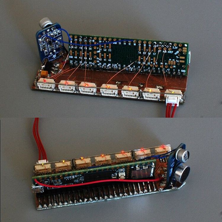
![]()
Above: sketchy prototyping techniques featuring a Teensy 3.5 and an Adafruit MAX4466 electret mic board. Advantage: I was able to cobble this together from stuff I had on hand in a few hours. Disadvantage: it's quite delicate (especially the LEDs).
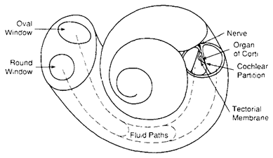
The cochlea is a spiral hollow structure in the inner ear that does the dirty work of converting sound into neural impulses. I won't get into detail on its workings here -- it's a fascinating system that is worthy of deep study -- beyond the parts relevant to this build.
![]()
Above: a diagram of the cochlea from here.
The cochlea is filled with a fluid that moves in response to sound entering the ear; the fluid in turn moves thousands of hair cells, each of which triggers nerve cells that send electrical signals to the brain. Due to their location along the fluid path (along with the varied stiffness of the basilar membrane), the hair cells respond to different frequencies.
There are many ways we could simulate the ear, the simplest being an sound-pressure-level-to-firing-rate converter of some sort. Conversely, a faithful full-scale reproduction of the organ would have thousands of outputs tuned to distinct frequencies, along with an input method to simulate the extra hairs used to 'tune' the mechanical preamplification system that exists in the real ear. We opted for something in between: some frequency selectivity but hopefully not too much bulk or cost.
Above: kinda hard to see, and the harmonica skills are severely lacking. But it works.
The prototype makes liberal use of @Paul Stoffregen's excellent #Teensy Audio Library -- in particular, the 1024-bucket FFT function. The code, shown below, doesn't do much beyond (a) grab specific buckets, (b) scale the FFT values, and (c) map those values to LED brightness. The output ports don't do anything yet, and eventually the brightness values will be converted into firing rates... but you get the idea.
#include <Audio.h> #include <Wire.h> #include <SPI.h> #include <SD.h> #include <SerialFlash.h> // GUItool: begin automatically generated code AudioInputAnalog adc1; //xy=227,187 AudioAnalyzeFFT1024 fft1024_1; //xy=480,289 AudioConnection patchCord1(adc1, fft1024_1); // GUItool: end automatically generated code // LED pin identities int pinLED0 = 35; int pinLED1 = 36; int pinLED2 = 37; int pinLED3 = 20; int pinLED4 = 21; int pinLED5 = 22; int pinLED6 = 23; // FFT reading array float input_array[7] = {0,0,0,0,0,0,0}; // FFT max value array float max_array[7] = {0.01,0.01,0.01,0.01,0.01,0.01,0.01}; // FFT value scaling array float scale_array[7] = {0.08, 0.10, 0.14, 0.3624, 0.3068, 0.46, 0.7201}; // LED output array int led_array[7] = {0,0,0,0,0,0,0}; void setup() { AudioMemory(12); fft1024_1.windowFunction(AudioWindowNuttall1024); pinMode(pinLED0, OUTPUT); pinMode(pinLED1, OUTPUT); pinMode(pinLED2, OUTPUT); pinMode(pinLED3, OUTPUT); pinMode(pinLED4, OUTPUT); pinMode(pinLED5, OUTPUT); pinMode(pinLED6, OUTPUT); } void getSamples() { // fills input_array[7] with FFT readings input_array[0] = fft1024_1.read(10,12); input_array[1] = fft1024_1.read(13,15); input_array[2] = fft1024_1.read(16,19); input_array[3] = fft1024_1.read(22,25); input_array[4] = fft1024_1.read(28,31); input_array[5] = fft1024_1.read(35,37); input_array[6] = fft1024_1.read(47,49); } void applyMinimum(float minimum) { // cuts off the lowest part of the FFT result (noise) int i; for (i=0;i<7;i++) { if (input_array[i] < minimum) { input_array[i] = 0; } } } void keepMaximum() { // keeps the maximum FFT values from input_array in max_array int i; for (i=0;i<7;i++) { if (input_array[i] > max_array[i]) { max_array[i] = input_array[i]; } } } void scaleOutput() { // scales led_array (0-255) based on scale_array int i; for (i=0;i<7;i++) { led_array[i] = (input_array[i] / scale_array[i]) * 255; if (led_array[i] > 255) { led_array[i] = 255; } } } void updateLEDs() { // updates the LEDs with the current led_array values analogWrite(pinLED0, led_array[0]); analogWrite(pinLED1, led_array[1]); analogWrite(pinLED2, led_array[2]); analogWrite(pinLED3, led_array[3]); analogWrite(pinLED4, led_array[4]); analogWrite(pinLED5, led_array[5]); analogWrite(pinLED6, led_array[6]); } void loop() { int i; if (fft1024_1.available()) { getSamples(); applyMinimum(0.01); keepMaximum(); scaleOutput(); updateLEDs(); Serial.print("FFT raw output: "); for (i=0;i<7;i++) { Serial.print(input_array[i],4); Serial.print("\t"); Serial.print(led_array[i]); Serial.print("\t\t"); } Serial.println(); } } -
A New Design Direction (plus some excellent news)
03/23/2017 at 15:46 • 2 commentsSince its inception in late 2014, this Hackaday.io page has focused on the technical details of the NeuroBytes project. I try to cover everything from component selection to scaling challenges to firmware development to failed tangents; while I undoubtedly leave quite a bit out, from the engineering perspective I consider this running log to be reasonably comprehensive.
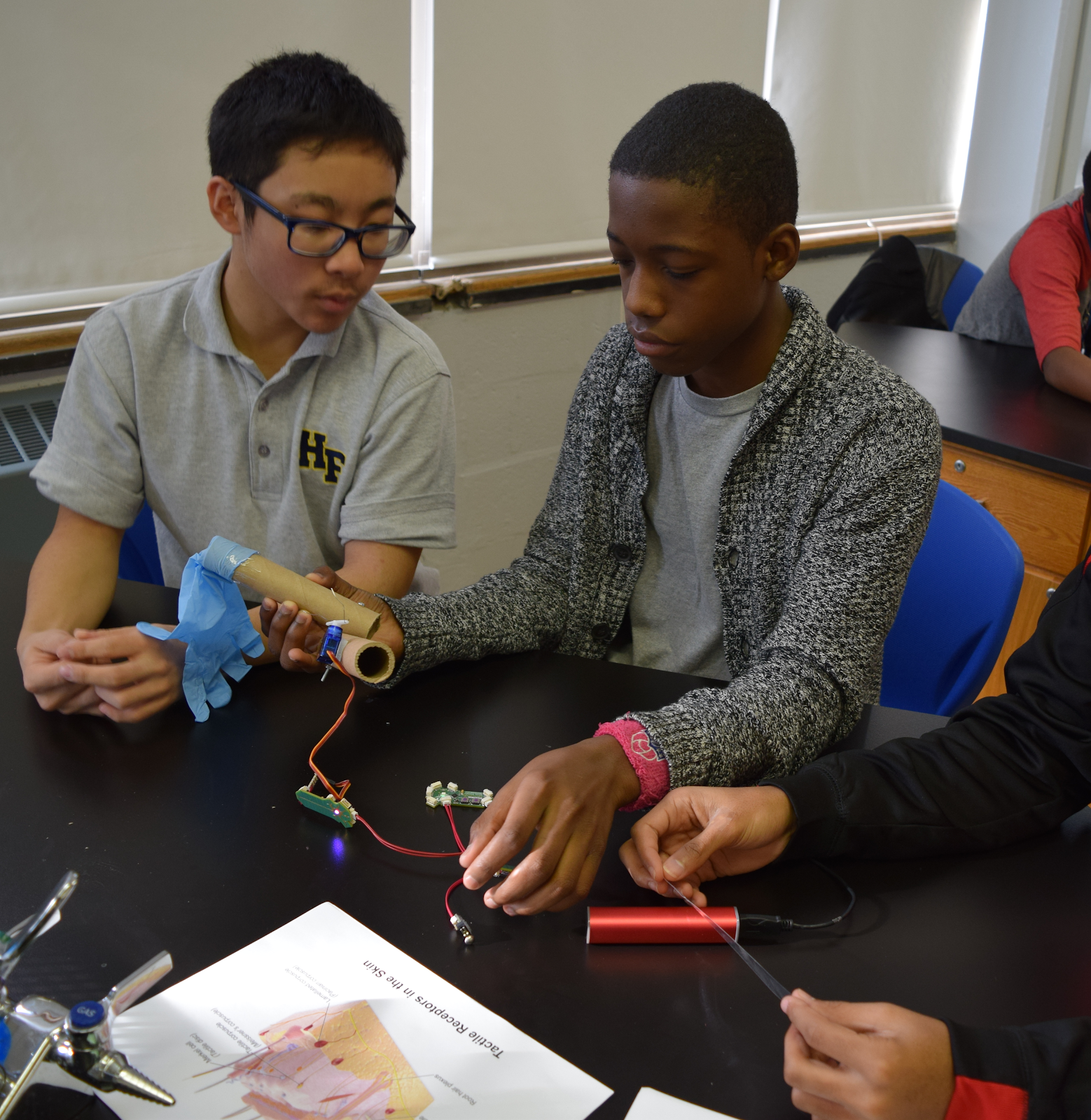
Getting the product in front of our end users -- primarily high school students, but also younger (middle school) and older (college) folks -- has also been a priority, just one that we don't talk about quite as frequently. By the numbers, we've sold NeuroBytes prototype kits into a dozen high school classrooms and two college neuroscience departments, and @NeuroJoe and I (but mostly him) have brought the platform into many more formal and informal learning environments (as shown in the image above). These interactions have driven our iterations starting with v0.4 and continuing through the green v0.91 boards we built last year.
Stuff We've Learned from Users
This won't be anything close to a comprehensive list; I'm focusing on lessons learned that are immediately relevant to future product development plans.
- Mode switches are confusing. Using a single base NeuroBytes board to do everything -- integrate-and-fire neuron simulation, motor neuron functionality, etc -- is great for minimizing SKUs, but it's confusing to new users. Every time we teach the patellar reflex kit, a few students end up setting an upstream interneuron into motor mode by mistake. As motor neurons directly output a servo-ready PWM signal -- i.e. a 50 Hz, 5% duty cycle square wave -- downstream neurons see an extremely rapid series of pulses, saturating their membrane potential value and holding the LED in a constant bright white state. This problem will grow more pronounced as we add new operating modes.
- Detailed PCB art is worthwhile. Students look carefully at NeuroBytes and notice just about everything -- that means the details need to be physiologically accurate. The gold-rendered NeuroBytes logo catches the eye and suggests a relationship to neuroscience, but the stylized design isn't perfect from an educational perspective. Specifically, dendrites should be more branched and spindly; the axon terminal should be longer and clearly split to output connectors; we should illustrate myelination; etc.
- Cables are too short. The stubby cables overly constrain even the simplest circuits, while the long cables still aren't long enough to adequately separate battery packs or sensors from circuits.
- We need dedicated power connectors. I had to see this problem first-hand to understand its importance. We spend a good deal of time teaching directionality (i.e. information flows only from dendrite to axon), and then tell students that power connections can plug into any free terminal. I view this as a convenience, but students see it as an exception to a fundamental rule!
- Our ecosystem is novel and has educational value, but it's not comprehensive enough. This was a hard truth, and one that took a long time to really believe. NeuroBytes don't have a ton of replay value and can't teach much beyond basic neuronal function, simply because they don't do much beyond blink LEDs and twitch motors. While teachers have enthusiastically accepted the platform and students are interested, the product doesn't have staying power because it lacks the flexibility for truly free exploration. In other words, we need to provide more options for input and output modules.
Product Development Plans
![]()
[above: new Motor Neuron prototype, featuring three equal-weight dendrites; a 'scope/programming port; two servo headers; and a revised PCB outline and look.]
Short answer: it's time for a massive prototyping sprint.
We're going to design and build a number of dedicated NeuroBytes modules, including a few concepts that we haven't explored at all yet (such as a model of the cochlea). Generally speaking, the modules will be single-purpose and designed to closely emulate (visually and functionally) real parts of the nervous system. On July 10th, we're hosting a week long workshop with two dozen high school educators where we'll test concepts, develop curriculum, get feedback, and do a few more iterations in advance of a more formal Fall '17 product ecosystem launch. Many more details to come -- I will try to post specifics related to a few modules in the coming months.
Hey what about the excellent news?
We got our Phase II grant from the National Science Foundation. This funding will provide adequate R&D resources to take us through commercialization. In other words: NeuroBytes continues to be my full-time job, but now I can (once again) get paid.
Yay!!
-
NeuroBytes v0.92 Prototype
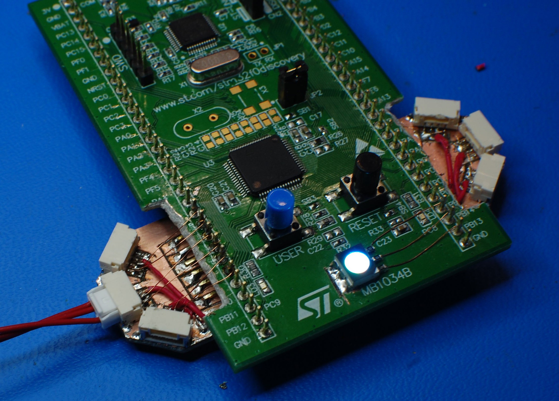
02/14/2017 at 22:45 • 0 commentsToday, the NeuroBytes project takes its first baby step into the 21st century.
![]()
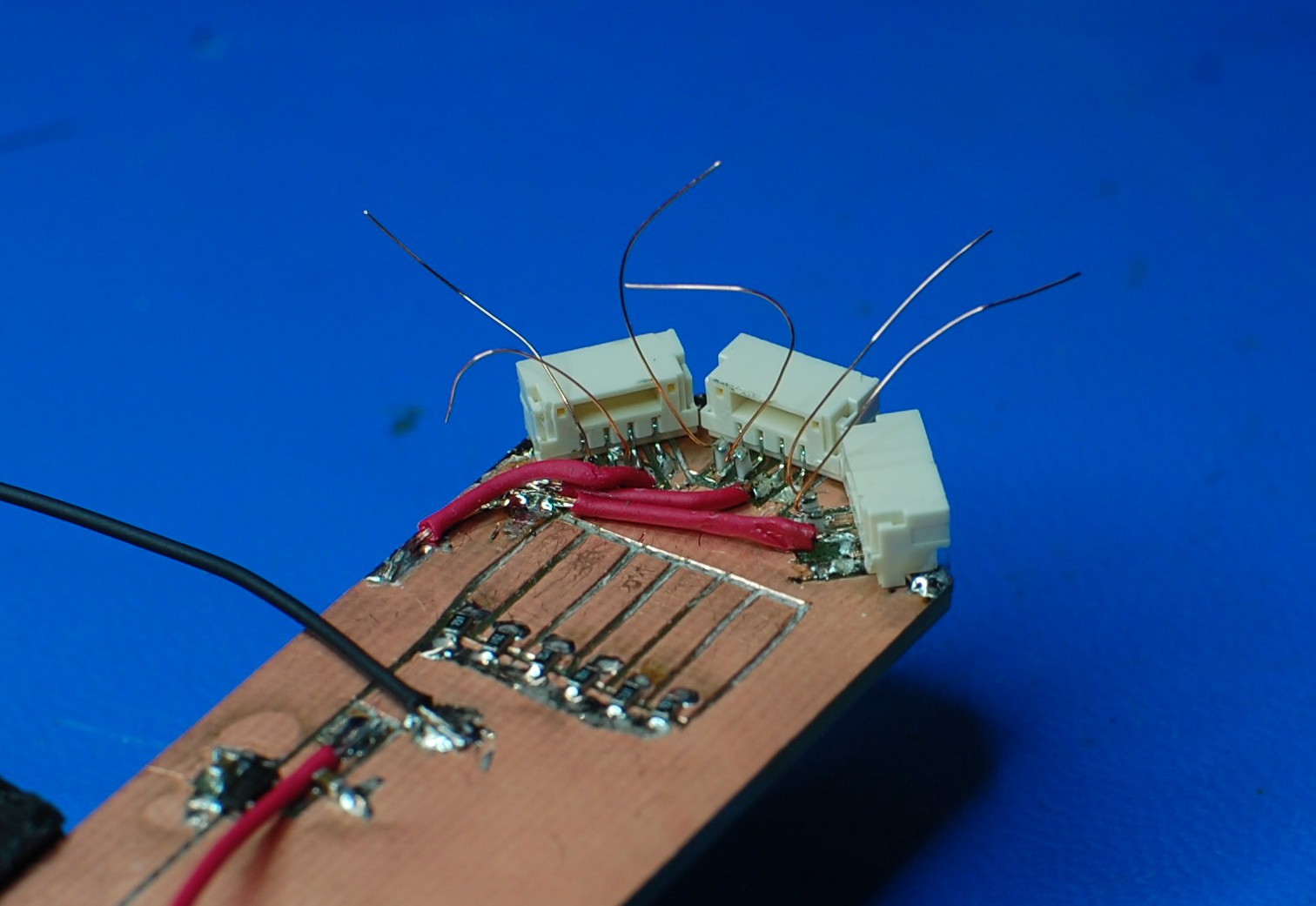
Okay, ignore the extremely sketchy construction techniques. It's an STM32F0 Discovery board, chosen due to its extremely low cost (under $10) and built-in ST-LINK programmer. My modifications include an RGB LED tied into the output compare registers of TIM1, along with a bottom-mounted 'sled' that includes power/ground rails, a 3.3vdc regulator, voltage dividers for the three dendrite signal/type pairs, and a diode for the bridged axon signal/type lines:
![]()
The decision to move to a 32-bit platform, and the selection of the STM32F0 specifically (-L0, potentially), wasn't one I made lightly. I am fairly comfortable with the ATtiny line at this point, a chip I have used for NeuroBytes since v0.4 in 2014. ATtinys are cheap, they have plenty of I/O, they use extremely simple open-source command line tools for programming, and the complete manual is under 250 pages. However, ATtiny88s (my current model of choice) doubled in price last year, meaning the STM32F0 is actually the economical option. And the other advantages of the new chipset -- enough hardware PWM channels for the RGB LED, vastly superior math capabilities due to speed and bit width improvements, online debugging capabilities using st-link and gdb, etc -- make the inconveniences (3.3VDC power, different development environment, etc) worthwhile.
The board is wired up as follows:
PIN FUNCTION PB13 / TIM1_CH1N RGB LED Red PB14 / TIM1_CH2N RGB LED Green PB15 / TIM1_CH3N RGB LED Blue PA6 Dendrite 1 Type PA7 Dendrite 1 Signal PC4 Dendrite 2 Type PC5 Dendrite 2 Signal PB0 Dendrite 3 Type PB1 Dendrite 3 Signal PC8 / TIM3_CH3 Axon Type/Signal (all) The non-standard dendrite/axon quantity isn't important -- it's just based on how much FR4 I wanted to dedicate to this build. The resistor dividers and power supply should make this prototype compatible with existing v0.91 stuff; the diode in the axon circuit is there to protect the processor in case they are hooked up to outputs by mistake.
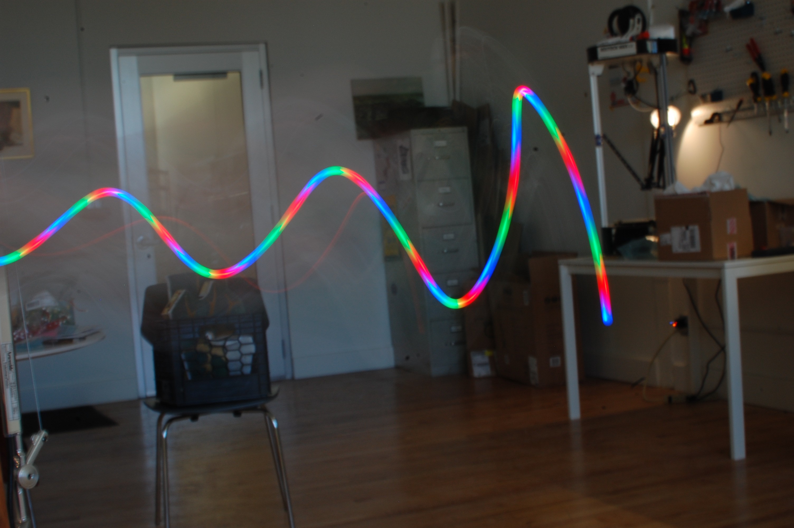
I've been playing around with libopencm3, an open-source firmware library for a variety of ARM Cortex microcontrollers. Getting the toolchain set up and working reliably wasn't particularly simple, but instructions in the official example repository eventually got me there. I wrote a simple program that uses the TIMER1 peripheral to PWM the LED at an extremely high rate (5 kHz) and resolution (10 bits per channel, gamma-corrected), producing some excellent effects:
![]()
above: 1/3 second exposure at F16 (ish) and ISO 200, feat. plenty of board-waving.
Code for the LED PWM test is shown below, including an unnecessarily large gamma correction lookup table. No further commentary at the bottom of the code block, so feel free to stop reading now (recommended).
/* * This file is part of the libopencm3 project. * * Copyright (C) 2013 Chuck McManis * Copyright (C) 2013 Onno Kortmann * Copyright (C) 2013 Frantisek Burian (merge) * * This library is free software: you can redistribute it and/or modify * it under the terms of the GNU Lesser General Public License as published by * the Free Software Foundation, either version 3 of the License, or * (at your option) any later version. * * This library is distributed in the hope that it will be useful, * but WITHOUT ANY WARRANTY; without even the implied warranty of * MERCHANTABILITY or FITNESS FOR A PARTICULAR PURPOSE. See the * GNU Lesser General Public License for more details. * * You should have received a copy of the GNU Lesser General Public License * along with this library. If not, see . */ /* RGB LED PWM test using an STM32F0 discovery board. Red PB13 TIM1_CH1N Green PB14 TIM1_CH2N Blue PB15 TIM1_CH3N */ #include <libopencm3/stm32/rcc.h> #include <libopencm3/stm32/gpio.h> #include <libopencm3/stm32/timer.h> #include <libopencm3/cm3/nvic.h> #include <libopencm3/cm3/systick.h> volatile uint8_t tick = 0; static const uint16_t gamma_lookup[] = { /* gamma = 2, input range = 0-1023, output range = 0-9600 */ 0, 0, 0, 0, 0, 0, 0, 0, 1, 1, 1, 1, 1, 2, 2, 2, 2, 3, 3, 3, 4, 4, 4, 5, 5, 6, 6, 7, 7, 8, 8, 9, 9, 10, 11, 11, 12, 13, 13, 14, 15, 15, 16, 17, 18, 19, 19, 20, 21, 22, 23, 24, 25, 26, 27, 28, 29, 30, 31, 32, 33, 34, 35, 36, 38, 39, 40, 41, 42, 44, 45, 46, 48, 49, 50, 52, 53, 54, 56, 57, 59, 60, 62, 63, 65, 66, 68, 69, 71, 73, 74, 76, 78, 79, 81, 83, 85, 86, 88, 90, 92, 94, 95, 97, 99,101,103,105,107,109,111,113, 115,117,119,121,123,126,128,130,132,134,137,139,141,143,146,148, 150,153,155,157,160,162,165,167,170,172,175,177,180,182,185,188, 190,193,196,198,201,204,206,209,212,215,218,220,223,226,229,232, 235,238,241,244,247,250,253,256,259,262,265,268,271,275,278,281, 284,287,291,294,297,301,304,307,311,314,317,321,324,328,331,335, 338,342,345,349,352,356,360,363,367,371,374,378,382,386,389,393, 397,401,405,408,412,416,420,424,428,432,436,440,444,448,452,456, 460,464,469,473,477,481,485,489,494,498,502,507,511,515,520,524, 528,533,537,542,546,551,555,560,564,569,573,578,583,587,592,596, 601,606,611,615,620,625,630,634,639,644,649,654,659,664,669,674, 679,684,689,694,699,704,709,714,719,724,729,735,740,745,750,756, 761,766,771,777,782,788,793,798,804,809,815,820,826,831,837,842, 848,853,859,865,870,876,882,887,893,899,904,910,916,922,928,933, 939,945,951,957,963,969,975,981,987,993,999,1005,1011,1017,1023,1029, 1036,1042,1048,1054,1060,1067,1073,1079,1086,1092,1098,1105,1111,1117,1124,1130, 1137,1143,1150,1156,1163,1169,1176,1182,1189,1195,1202,1209,1215,1222,1229,1236, 1242,1249,1256,1263,1269,1276,1283,1290,1297,1304,1311,1318,1325,1332,1339,1346, 1353,1360,1367,1374,1381,1388,1395,1402,1410,1417,1424,1431,1439,1446,1453,1460, 1468,1475,1482,1490,1497,1505,1512,1520,1527,1534,1542,1550,1557,1565,1572,1580, 1587,1595,1603,1610,1618,1626,1634,1641,1649,1657,1665,1673,1680,1688,1696,1704, 1712,1720,1728,1736,1744,1752,1760,1768,1776,1784,1792,1800,1808,1817,1825,1833, 1841,1849,1858,1866,1874,1882,1891,1899,1907,1916,1924,1933,1941,1949,1958,1966, 1975,1983,1992,2001,2009,2018,2026,2035,2044,2052,2061,2070,2078,2087,2096,2105, 2114,2122,2131,2140,2149,2158,2167,2176,2185,2194,2202,2211,2220,2230,2239,2248, 2257,2266,2275,2284,2293,2302,2312,2321,2330,2339,2349,2358,2367,2377,2386,2395, 2405,2414,2424,2433,2442,2452,2461,2471,2480,2490,2500,2509,2519,2528,2538,2548, 2557,2567,2577,2586,2596,2606,2616,2626,2635,2645,2655,2665,2675,2685,2695,2705, 2715,2725,2735,2745,2755,2765,2775,2785,2795,2805,2815,2826,2836,2846,2856,2866, 2877,2887,2897,2908,2918,2928,2939,2949,2959,2970,2980,2991,3001,3012,3022,3033, 3043,3054,3065,3075,3086,3097,3107,3118,3129,3139,3150,3161,3172,3182,3193,3204, 3215,3226,3237,3248,3258,3269,3280,3291,3302,3313,3324,3335,3347,3358,3369,3380, 3391,3402,3413,3425,3436,3447,3458,3470,3481,3492,3503,3515,3526,3538,3549,3560, 3572,3583,3595,3606,3618,3629,3641,3652,3664,3676,3687,3699,3711,3722,3734,3746, 3757,3769,3781,3793,3804,3816,3828,3840,3852,3864,3876,3888,3900,3912,3924,3936, 3948,3960,3972,3984,3996,4008,4020,4032,4044,4057,4069,4081,4093,4106,4118,4130, 4142,4155,4167,4180,4192,4204,4217,4229,4242,4254,4267,4279,4292,4304,4317,4329, 4342,4355,4367,4380,4393,4405,4418,4431,4444,4456,4469,4482,4495,4508,4521,4533, 4546,4559,4572,4585,4598,4611,4624,4637,4650,4663,4676,4690,4703,4716,4729,4742, 4755,4769,4782,4795,4808,4822,4835,4848,4862,4875,4888,4902,4915,4929,4942,4956, 4969,4983,4996,5010,5023,5037,5050,5064,5078,5091,5105,5119,5132,5146,5160,5174, 5187,5201,5215,5229,5243,5257,5271,5284,5298,5312,5326,5340,5354,5368,5382,5396, 5411,5425,5439,5453,5467,5481,5495,5510,5524,5538,5552,5567,5581,5595,5610,5624, 5638,5653,5667,5682,5696,5710,5725,5739,5754,5769,5783,5798,5812,5827,5842,5856, 5871,5886,5900,5915,5930,5944,5959,5974,5989,6004,6019,6033,6048,6063,6078,6093, 6108,6123,6138,6153,6168,6183,6198,6213,6228,6243,6259,6274,6289,6304,6319,6335, 6350,6365,6380,6396,6411,6426,6442,6457,6473,6488,6503,6519,6534,6550,6565,6581, 6596,6612,6628,6643,6659,6674,6690,6706,6722,6737,6753,6769,6784,6800,6816,6832, 6848,6864,6879,6895,6911,6927,6943,6959,6975,6991,7007,7023,7039,7055,7071,7088, 7104,7120,7136,7152,7168,7185,7201,7217,7233,7250,7266,7282,7299,7315,7332,7348, 7364,7381,7397,7414,7430,7447,7463,7480,7496,7513,7530,7546,7563,7580,7596,7613, 7630,7646,7663,7680,7697,7714,7730,7747,7764,7781,7798,7815,7832,7849,7866,7883, 7900,7917,7934,7951,7968,7985,8002,8019,8037,8054,8071,8088,8105,8123,8140,8157, 8175,8192,8209,8227,8244,8261,8279,8296,8314,8331,8349,8366,8384,8401,8419,8436, 8454,8472,8489,8507,8525,8542,8560,8578,8595,8613,8631,8649,8667,8685,8702,8720, 8738,8756,8774,8792,8810,8828,8846,8864,8882,8900,8918,8936,8954,8972,8991,9009, 9027,9045,9063,9082,9100,9118,9137,9155,9173,9192,9210,9228,9247,9265,9284,9302, 9321,9339,9358,9376,9395,9413,9432,9450,9469,9488,9506,9525,9544,9563,9581,9600 }; void sys_tick_handler(void) { tick = 1; } static void systick_setup(int freq) { systick_set_clocksource(STK_CSR_CLKSOURCE_AHB); STK_CVR = 0; systick_set_reload(rcc_ahb_frequency / freq); systick_counter_enable(); systick_interrupt_enable(); } static void clock_setup(void) { rcc_clock_setup_in_hsi_out_48mhz(); } static void gpio_setup(void) { /* Enable GPIOB clock */ rcc_periph_clock_enable(RCC_GPIOB); /* Set PB13, PB14, and PB15 to alternative function with no pullup/pulldown */ gpio_mode_setup(GPIOB, GPIO_MODE_AF, GPIO_PUPD_NONE, GPIO13 | GPIO14 | GPIO15); /* Set PB13, PB14, and PB15 output options: push-pull, high speed */ gpio_set_output_options(GPIOB, GPIO_OTYPE_PP, GPIO_OSPEED_HIGH, GPIO13 | GPIO14 | GPIO15); /* Set PB13, PB14, and PB15 to alternative function AF2 to enable TIM1_CH1N, TIM1_CH2N, and TIM1_CH3N outputs */ gpio_set_af(GPIOB, GPIO_AF2, GPIO13 | GPIO14 | GPIO15); } static void tim_setup(void) { /* Enable and reset TIM1 clock */ rcc_periph_clock_enable(RCC_TIM1); timer_reset(TIM1); /* Set TIM1 mode to no clock divider ratio, edge alignment, and up direction */ timer_set_mode(TIM1, TIM_CR1_CKD_CK_INT, TIM_CR1_CMS_EDGE, TIM_CR1_DIR_UP); /* Set prescaler to 0: 48 MHz clk */ timer_set_prescaler(TIM1, 0); /* Set timer period to 9600: 5 kHz PWM with 9600 steps */ timer_set_period(TIM1, 9600); /* Must be called for advanced timers */ timer_enable_break_main_output(TIM1); /* Set TIM1 Output Compare mode to PWM2 on channels 1N, 2N, and 3N */ timer_set_oc_mode(TIM1, TIM_OC1, TIM_OCM_PWM1); timer_set_oc_mode(TIM1, TIM_OC2, TIM_OCM_PWM1); timer_set_oc_mode(TIM1, TIM_OC3, TIM_OCM_PWM1); /* Set starting output compare values */ timer_set_oc_value(TIM1, TIM_OC1, 0); timer_set_oc_value(TIM1, TIM_OC2, 0); timer_set_oc_value(TIM1, TIM_OC3, 0); /* Enable outputs */ timer_enable_oc_output(TIM1, TIM_OC1N); timer_enable_oc_output(TIM1, TIM_OC2N); timer_enable_oc_output(TIM1, TIM_OC3N); /* Enable counter */ timer_enable_counter(TIM1); } static void led_rgb(uint16_t r, uint16_t g, uint16_t b) { timer_set_oc_value(TIM1, TIM_OC1, gamma_lookup[r]); timer_set_oc_value(TIM1, TIM_OC2, gamma_lookup[g]); timer_set_oc_value(TIM1, TIM_OC3, gamma_lookup[b]); } uint8_t i; static void breakpoint(void) { if (i == 0) { i = 1; } else { i = 0; } } int main(void) { clock_setup(); gpio_setup(); tim_setup(); systick_setup(100000); uint16_t r = 1023; uint16_t g = 0; uint16_t b = 0; uint8_t stage = 0; while (1) { while (tick == 0) {} tick = 0; led_rgb(r,g,b); switch (stage) { case 0: //red to green { r--; g++; if (r == 0) { stage++; } break; } case 1: //green to blue { g--; b++; if (g == 0) { stage++; } break; } case 2: //blue to red { b--; r++; if (b == 0) { breakpoint(); stage = 0; } break; } } } } -
Chris 'n Zach blab about NeuroTinker, SBIR, and other random crap
01/07/2017 at 16:47 • 1 comment![]()
If you're exceedingly bored, I had the distinct honor of being on @Chris Gammell's excellent radio show this week, The Amp Hour. Listen to the episode here--we cover a lot in a brief (hah!) 109 minutes, including quite a bit about the history and challenges related to this very project. -
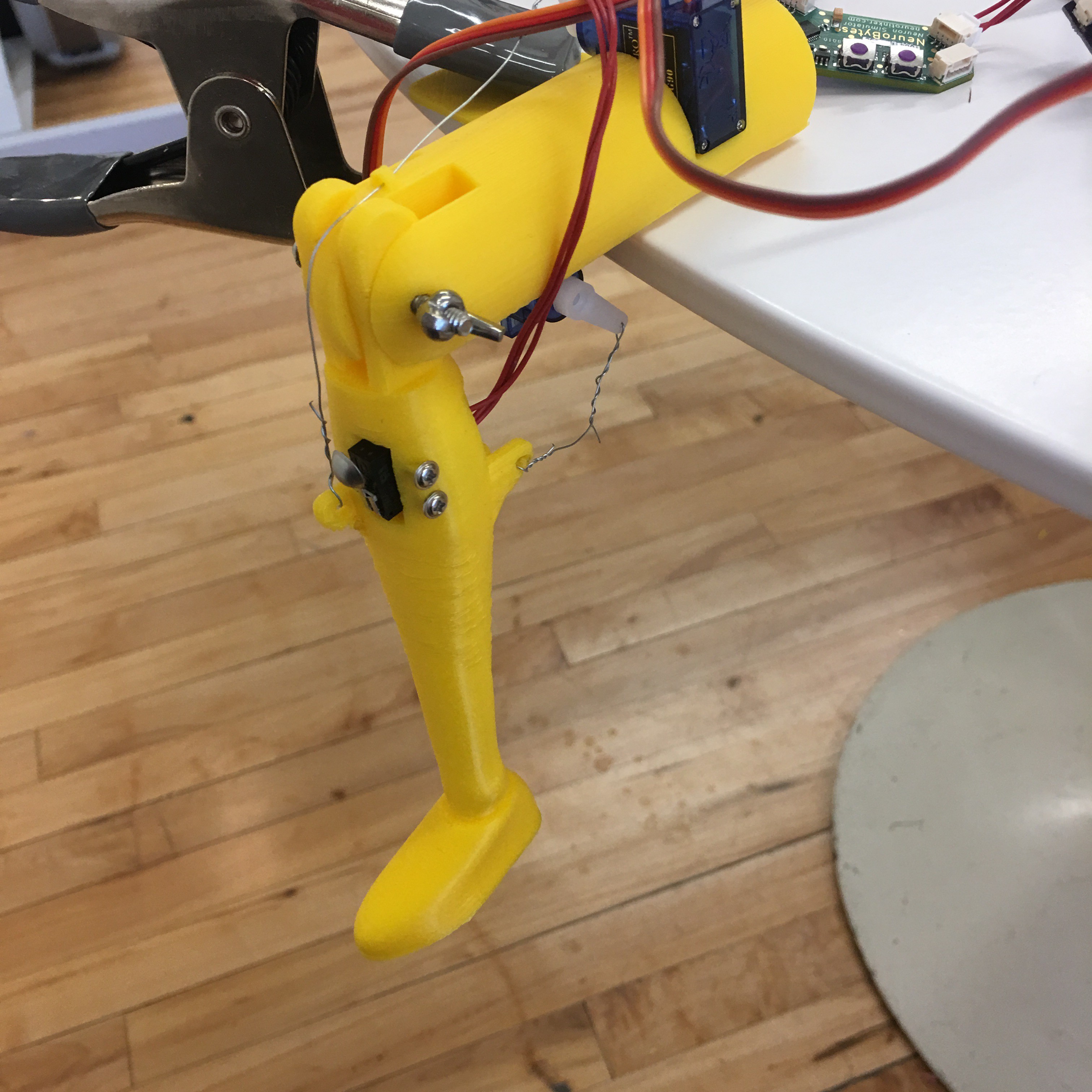
DIY Patellar Reflex (and a new intern!)
12/18/2016 at 01:00 • 0 commentsI’m Jarod and I’m a physics/electrical engineering student at the University of Minnesota and am really excited to be a newly hired intern at Neurotinker! My first project here has been to revamp the 3D-printable patellar reflex model. The original principles of the model have stayed the same: 3D print a leg and thigh piece and hook them up with four NeuroBytes, two servo motors, and a button to create a neurologically accurate model of the patellar reflex! My project was to make the 3D printing and assembly process as easy as possible so that users can focus more on learning neuroscience and less on intricate 3D printing and assembly.
The patellar reflex is a great starting model for new NeuroBytes users because it uses only four NeuroBytes and demonstrates a neurological phenomena that everybody recognizes (even an engineering student with no neuroscience experience :>). Two muscles cause the leg to involuntarily kick when the patellar ligament is struck--the quadricep and the hamstring. The quadricep sits on top of the thigh and its motor neurons are told to contract and jerk the leg when the patellar sensory neurons send a signal. The hamstring sits on the bottom of the thigh and normally stays contracted to keep the leg from moving--but an inhibitory signal from the patellar ligament tells it to relax and let the quadricep do its thing.![]()
[image by Amiya Sarkar, available on wikipedia here]
A button embedded in the leg model functions as the patellar tendon and is connected via an excitatory cable to a sensory neuron. An impulse from the button is enough to fire the sensory neuron and send an impulse through its axons. One axon is connected to the quadricep motor neuron via an excitatory cable and causes the quadricep to contract (i.e. move its servo motor) and pull the leg up. The other axon sends an inhibitory impulse to the hamstring motor neuron and goes through an interneuron on its way. Interneurons are located in the ‘processing centers’ of our body like the brain and spinal cord and routing signals through them causes a brief delay. In contrast, the signal from the patellar neuron to the quadricep motor neuron does not go through an interneuron which causes the reflex to happen more quickly and also makes it involuntary. The hamstring motor neuron relaxes (i.e. moves its servo) to allow the quadricep to move the leg in unison but doesn’t actually do any work in making the motion happen.
Building this model not only teaches students how neurons in our body function, but also shows how a simple kicking motion hides a ton of complexity in how a network of neurons, talking to each other only through brief electrical pulses, can coordinate motion.
![]()
The original patellar reflex model did this demonstration very well but was difficult to print and assemble. Printing was made difficult by the substantial amount of support structure necessary to get the thing printed which required a laborious, and sometimes painful, removal process. Assembly was difficult and mostly improvisational as the servos and button had to be mounted with tape and zip ties. The model’s support structure, which used four screws as a sort of tripod, was also finicky and unreliable.
My goal was to design a new model that could be printed without support structure and could be fully assembled easily and intuitively with only a couple parts from Home Depot or a local hardware store. Zach calls this design condition the ‘Home Depot test’ and, for this and future kits, is a very important design requirement that means users can create all sorts of cool models with NeuroBytes without having to buy costly custom-manufactured components. I also used a free CAD tool (Fusion 360) and will open source all of the design files so users can customize the model to their needs--and also contribute to a growing ecosystem of NeuroBytes models.
![]()
The first major change I made was to switch the anatomical skeleton leg to a cartoonish leg with a shoe. The skeleton leg had lots of small features and didn’t lay flat on the print bed which created unnecessary complications. The servo motors already come with screws that fit their mounting holes so I made the new servo housing use the screws instead of tape and zip ties. Each servo comes with two screws, but only one is necessary to mount each servo, so I used the two extra screws to mount the button inside the leg. Conveniently the servo screws fit the mounting holes on the button as well!
The new patellar reflex kit now hangs off the edge of a table and can be secured either with a clip ($0.99 at Home Depot) or with a book and something heavy. The servo motors are easily mounted in thigh insets with the supplied screws. The muscles are assembled by connecting a wire between the servos and connection holes on the leg. To mount the patellar tendon button, insert it in the form-fitted hole in the leg and secure it with the screws leftover from the servo. To finish the assembly, simply insert a 62-30 sized screw in the hole joining the knee and the thigh to act as an axle. The size of the hole can also be easily changed in Fusion 360 to fit any screw you might have lying around.
Now you can hook up some NeuroBytes in the patellar reflex configuration described above or create your own version!
-
Tedious testing suggests the connector selection is sound!
12/08/2016 at 18:21 • 0 commentsThe JST GH connector has served me well since its initial selection during the development of NeuroBytes v0.8. Prior to choosing this connector, we ran a few usability tests with customers to see which designs were intuitive to use (some pigtails have been lost to history):
![]()
The GH was the clear winner; its locking tab was easy to understand and simple to operate, and the connector's small width compared to some competitors was a bonus during the PCB design. Definitely better than the tiny SH series used in v0.5, v0.6, and v0.7.
However, larger concerns loomed on the horizon. The JST GH datasheet omits connector lifetime: the closest the document offers is 'initial contact resistance' (< 0.030 ohms) and 'contact resistance after environmental tests' (< 0.050 ohms). These connectors, as with nearly every other PCB-mounted header, aren't designed to be consumer-facing, like a micro USB or 1/8" phono plug. Rather, they are designed for single use during assembly, and perhaps subsequent use during hardware upgrades or repairs.
To date, we have built roughly 700 NeuroBytes boards that use the GH platform, and we have never observed an issue stemming from connector aging. Voltage drop across large networks is essentially negligible, and the additional 1 V headroom provided by the on-board LDO allows us to tolerate higher neuron-to-neuron contact resistance. On the flip side, a number of highly qualified individuals -- JST factory engineers, sales reps, independent electrical engineers, and others -- have raised valid concerns about connector aging, particularly as the failure mode would likely be quite frustrating to end users. No one likes intermittent connections.
Time for some instrumented tests.
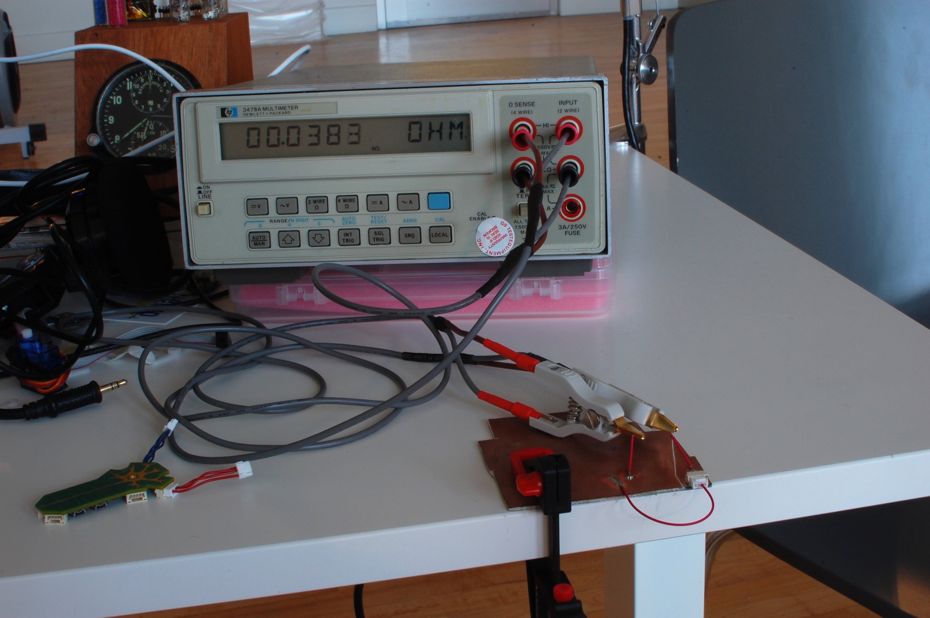
![]()
Finally an excuse to eBay a four-wire resistance meter! The HP 3478A isn't the newest bit of kit, but this one seems to work well enough (although it is not calibrated). I also picked up a set of unbranded Kelvin clips and a Prologix GPIB-USB adapter. Using the ++read command and gtkterm, I can now continuously log the meter reading to a text file. No time stamps, but it sure beats manual data entry.
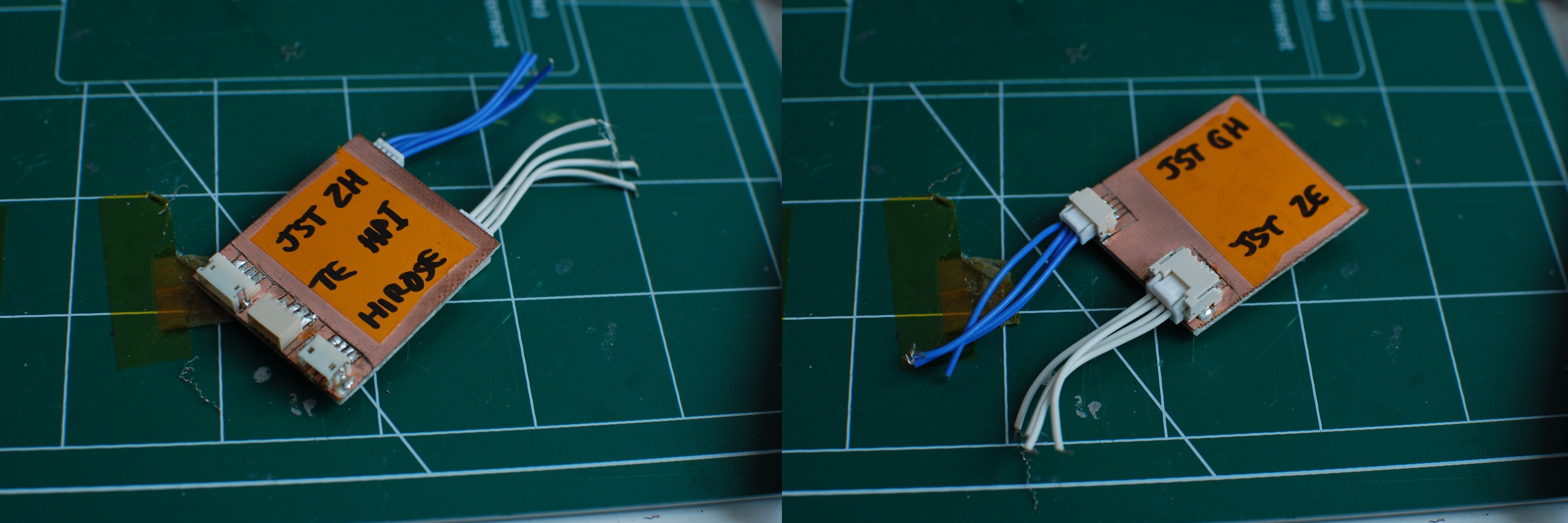
The test setup, shown above, is simple enough: I soldered an unused JST GH header to a slab of FR4 and assembled a matching connector which I also soldered down via a short pigtail. Then, I attached two additional leads for the Kelvin clips. The FR4 is clamped down, meaning the entire setup doesn't physically move during testing. It's not perfect -- the milliohm measurement includes the resistance of a bit of FR4, four solder joints, and ~20cm of wire -- but it's good enough to see how the contact resistance changes over time.
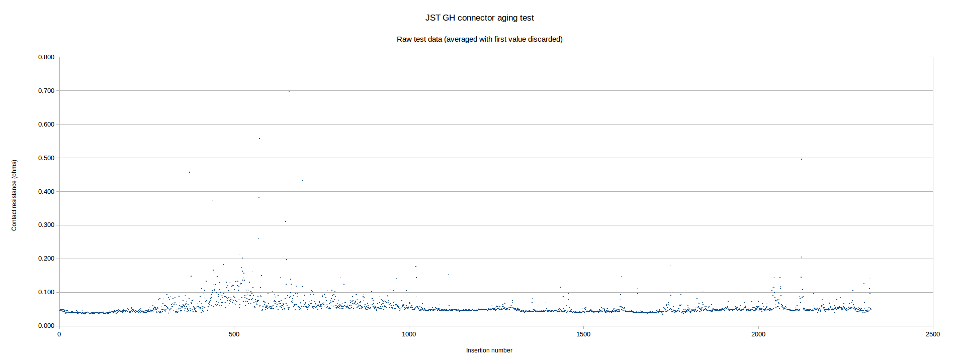
Next, I turned on a few Youtube teardown videos and manually cycled the connector 2,322 times. Each time I mated up the header, I left it connected long enough to get a handful of readings; during the data analysis, I dumped the first reading (it ranged from 10x to 1000x the stabilized measurement) and averaged the rest for each point:
![]()
[click the graph to see a larger image -- you'll likely have trouble reading the axes inline... ]
As you can see, the connector resistance is quite consistent for the first few hundred cycles -- roughly 40 milliohms. Near insertion 300, the resistance variability starts to increase, although in the vast majority of cases it still remains below 100 milliohms. Subsequently, the measurement stabilizes again and stays fairly constant for the remainder of the test.
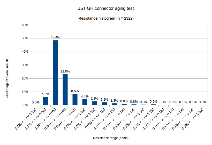
When I fitted a line to the data, the slope was almost exactly zero -- a great sign, as it suggests the connector contact resistance isn't gradually increasing. Additionally, the variability seemed to stabilize halfway through test. In order to better quantify this variability, I put together a histogram of the data:
![]()
As you can see, measurements over 100 milliohms aren't common. The data is also skewed away from normalcy -- the median value is 0.049 ohms, while the mean is 0.057 ohms.
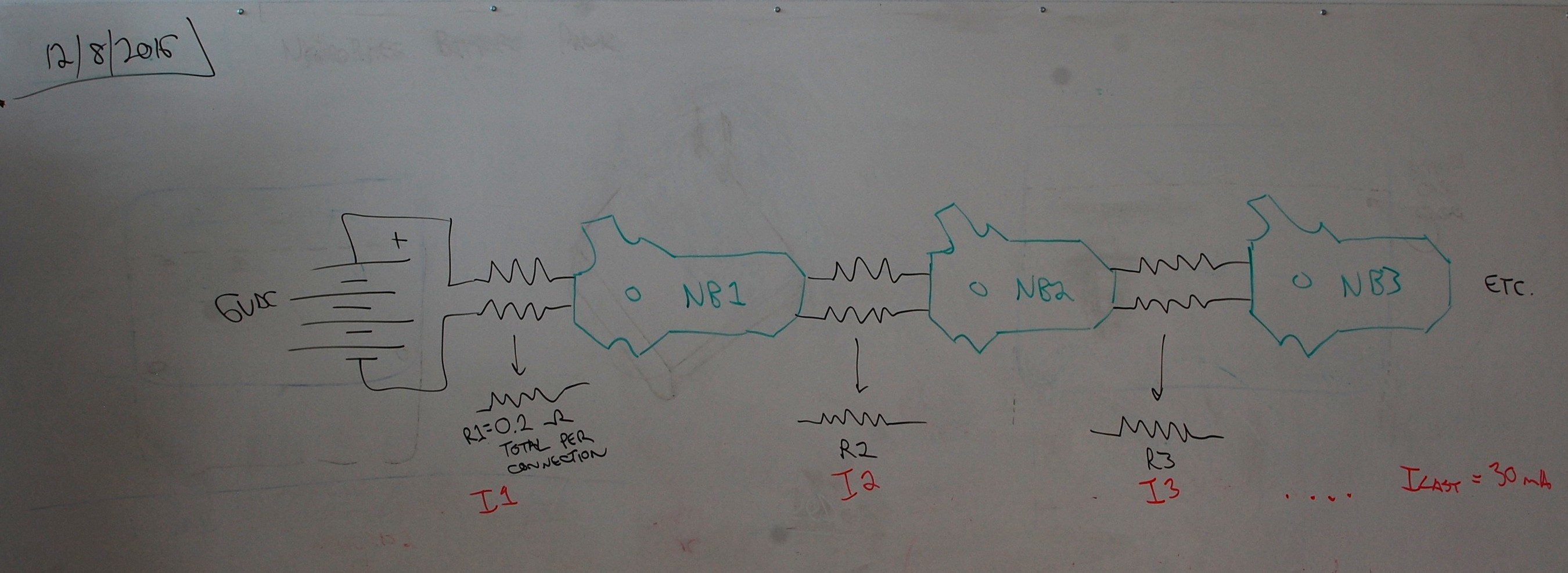
It's worth mentioning here that the real-world impact of contact resistance depends on a few factors -- specifically, the current draw of each NeuroBytes board, and the total length of the chain. If we make a few conservative assumptions:
- maximum chain between a NeuroBytes board and a power supply is 10 connections.
- individual contact resistance equal to values tested (i.e., each NB --> NB connection is 4x the recorded value: two ends and two power conductors per cable).
- average current draw per NeuroBytes board is 30 mA.
Using 0.05 ohms as the resistance value per connector, the chain can be modeled as follows:
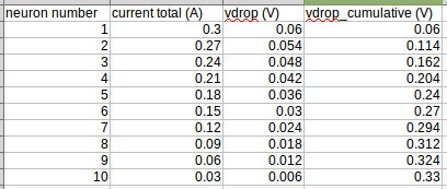
If I'm thinking about this the right way, (a) the resistances can be summed to equal 0.2 ohms per link; and (b) the current adds from the end of the chain. As such, the voltage drop across R1 will be the highest, since it passes the full network's current (300 mA):![]()
Everything about that calculation is conservative; in particular, our first kit design only has 6 NeuroBytes, so most users won't ever build a 10-neuron sequential chain. However, even if they did, the 0.33 V cumulative drop wouldn't be an issue, as the 5 V LDOs can operate well below 5.67 V input.![]()
Obviously servos can cause complications here; I've measured up to 750 mA for a stalled 9g servo, which would produce an additional 0.15 V drop per link. Yet another reason to consider local servo power supplies, I suppose.
Comments/suggestions/etc welcome. Once I'm satisfied this issue is put to bed I likely won't address it again for some time, so speak now if you think my test methodology or model could use some work!


)
 The final code at this point, working with 32bit ints on my personal computer follows. In my next log, I'll go through what it took me to get this running on my NeuroByte board and then how to get it running more quickly.
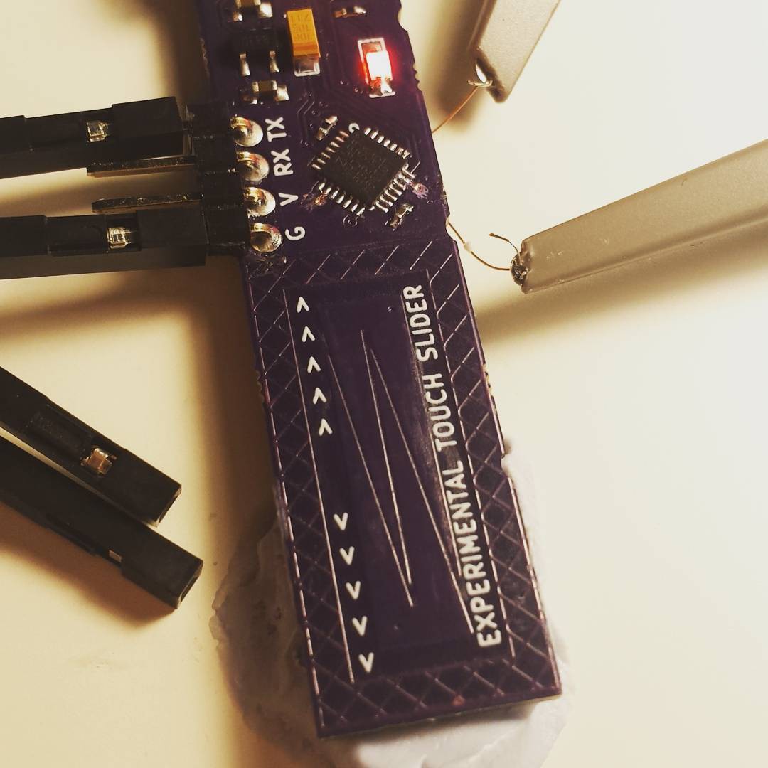


