Stefan Lochbrunner
-
Case design considerations
04/06/2015 at 00:27 • 0 commentsFirst off... here, have a rough sketch of what the device looks like:
![for the umpteenth time...]()
... as if I hadn't used it enough already ;)
TLDNR: SoB case templates on GitHub.
Seriously though, some thoughts on the case design:
As far as I can tell the most common ways to mount a rotary encoder are to solder it on top of the PCB (like all the modules found on eBay) or to directly mount it to the case.
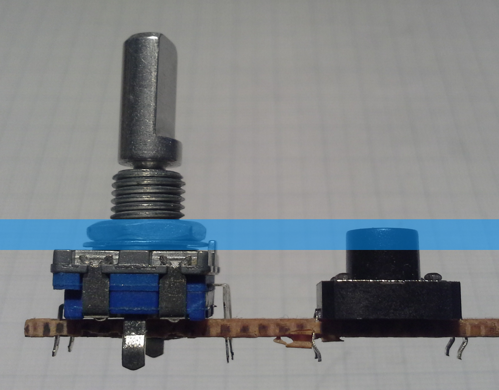
When combining it with buttons though, the first option is problematic because the body of the encoder is higher that the buttons. This results in the buttons not protruding far enough through the acrylic (blue stripe, roughly 2.5mm thick) as illustrated in this image:
![]()
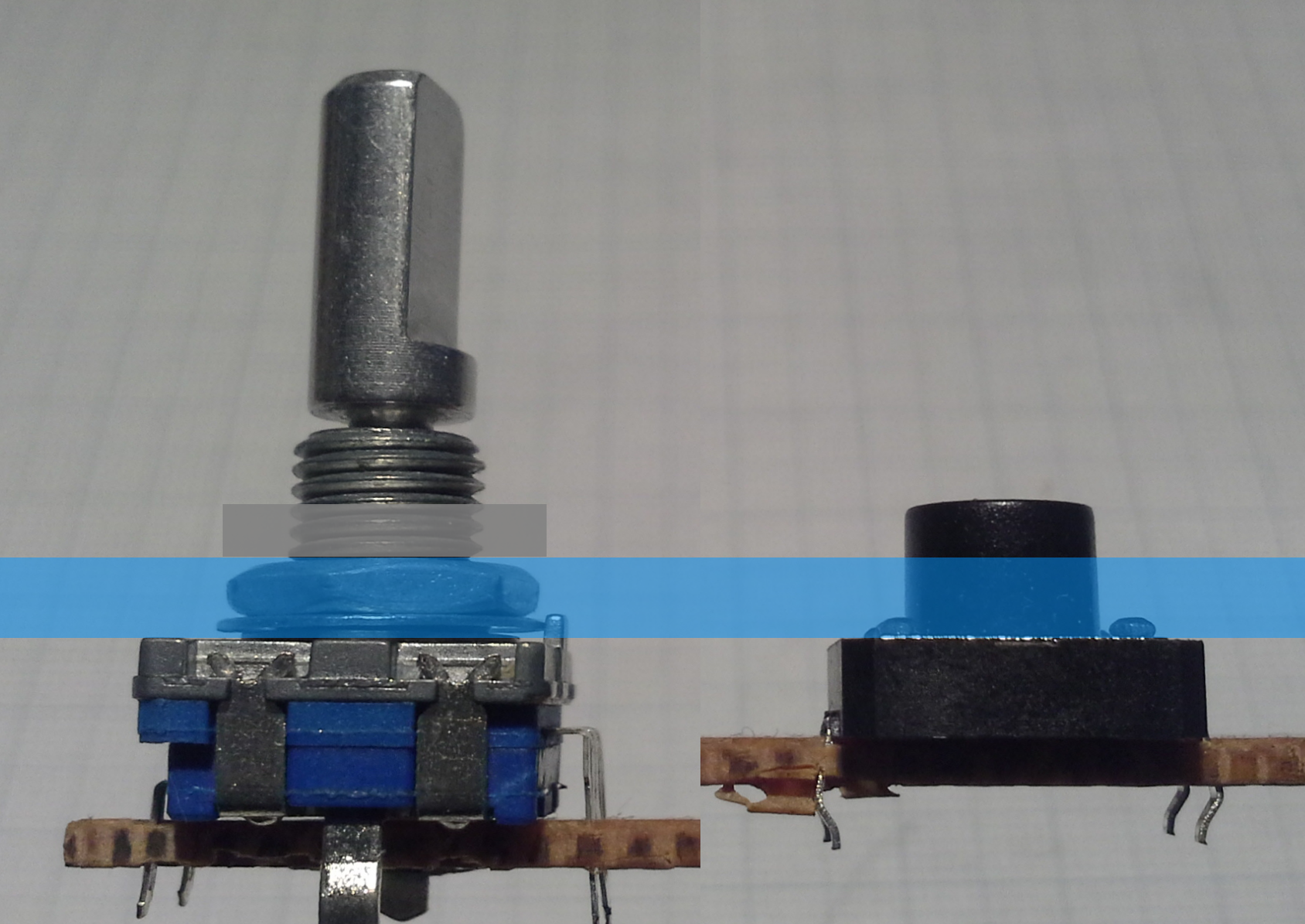
Of course this would have worked for the thinner tin case I used for the prototype but then the problem is that the threaded part of the shaft can't be shortened. This is also the case if the encoder is mounted to the case directly (the second possibility), as shown here:
![]()
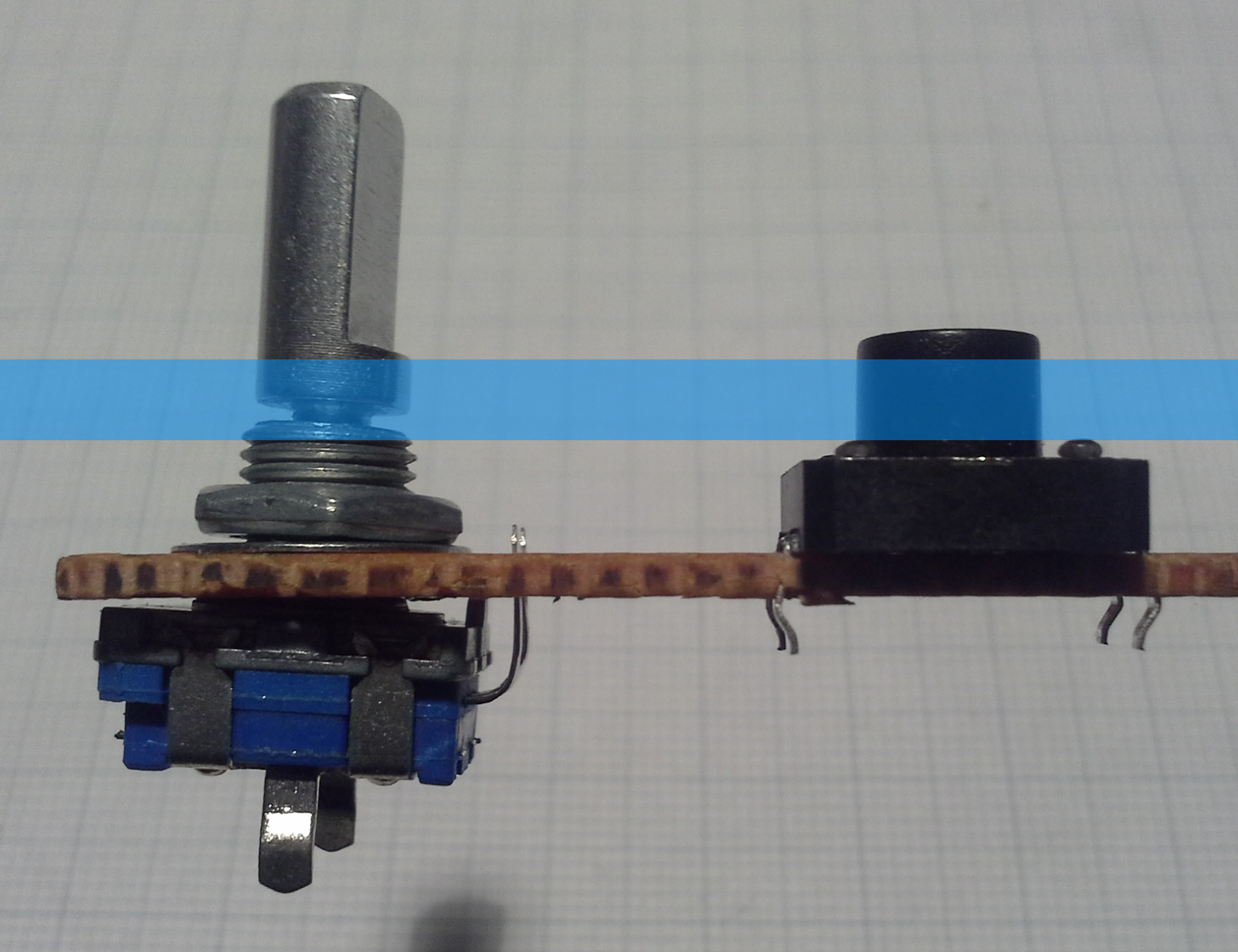
Another downside of this is that it requires two separate PCBs. Therefore I went with a third option that I haven't really seen anywhere else, which is to mount the encoder to the PCB. This leaves only the movable part of the shaft protruding through the acrylic:
![]()
This is where the hole in the center of the rotary encoder footprint on the PCB, that I mentioned before, comes into play. The encoder can then be connected to the same footprint as if it was mounted on top. However, bending the pins upward can cause them to break off (as you can see on the left of the rotary encoder) but that's an easy fix. It's also important to make sure that the pins are not shorted to the body of the encoder. If the rotary encoder shaft is still too long in this configuration it can be easily shortened such that the knob sits just barely above the acrylic.
That was a lot of text and three quite similar pictures (...again, with the reuse of images...) for something that is quite obvious I guess...
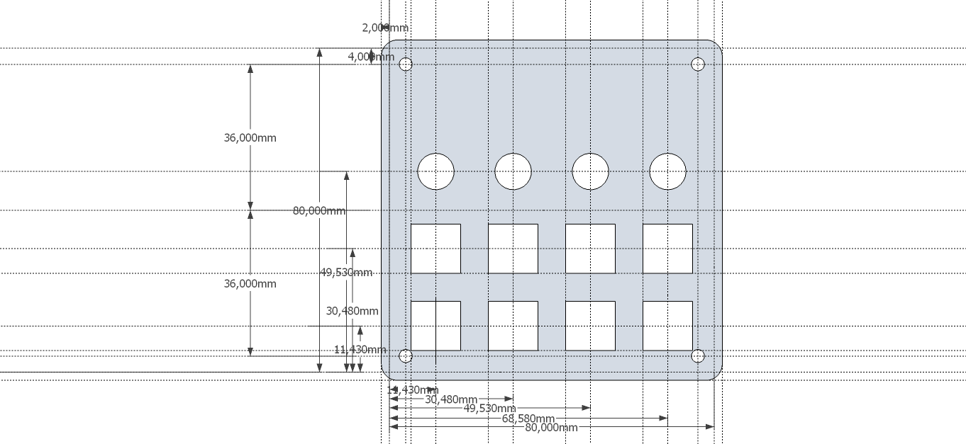
Anyway, for the the actual acrylic case I ordered custom laser cut pieces from Seeeds Fusion service for the top half and the blank DP8080 case for the bottom. I didn't run the numbers but maybe ordering custom cut pieces for the bottom would be cheaper than the blank cases since it's a less complex job. However, with the blank case I also get the screws and the standoffs so I don't have to buy them separately.
![]()
To design the case I followed DPs guide with some exceptions:
- If you are like me, follow the link for the SVG plugin and look straight for the download, you might miss the fact that the plugin have moved to GitHub. There you'll find the .rbz file that plays nicely with the current version (15.2.685) of SketchUp.
- Exporting as .svg with a line width of 0 resulted in an empty file so I set it to 0.1mm.
- Contrary to the guide, it says on the Fusion laser cutting page that they only accept .eps, .cdr or .dxf files. Therefore I converted my .svg file to .dxf using Inkscape. I first tried .eps but even re-opening that file with Inkscape resulted in wrong dimensions. The .dxf version of the file didn't show that problem with Inkscape, however, Seeed seems to use CorelDRAW where it imported incorrectly.
As you can see in the above image (and the files on GitHub), I made the openings for the buttons large enough to fit around the body of the button in case I want to use only 5mm high tact switches instead of the shown 8mm high ones.
-
A proper PCB
02/15/2015 at 22:01 • 0 commentsI have a lot of thoughts on this so I'll try to write them down somewhat coherently but the TLDNR is that I designed a PCB and would appreciate your feedback before I have it made.
During assembly of the prototype... no, actually during prototyping I began to think that I could use such a device, too. But when I was wiring up the prototype it became clear that there's no way that I'll go through that nightmare hellride again. And when other people expressed interest in such a device I decided to design a PCB.
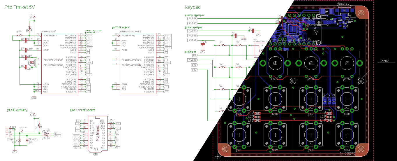
![]()
First off, I'd like to talk about the PCB size. I used the Dangerous Prototypes Sick of Beige (SoB) 80mm x 80mm template for two reasons
- It would fit in the same case that I used for the prototype
- Custom cases based on the SoB standard can be ordered (e.g. from Seeed)
Therefore the files for the PCB and the case sort of form a kit to build one yourself.
Next up, some comments about the schematic. As indicated in the image above (higher resolution image and file on GitHub) there are 3 MCUs... or at least the footprints are there. I really like how @jaromir.sukuba went about including the Pro Trinket in #Pavapro - portable AVR programmer as can be seen in this log. It gives you the option to either solder the Pro Trinket circuit yourself or just drop a purchased one in there. Additionally I included a TQFP footprint in case those are easier/cheaper to source for someone (me) or someone doesn't want to bother with soldering the QFN package (also me). I also left out unnecessary components (one for battery operation) and changed some others, most importantly the crystal because the HC-49/US package should be more widely available. Due to differences in the pinout of the SMD and DIL packages I also had to change some connections between the keypad/mode button and the MCU. You can see them in the schematics and I'll change them in the sketch when I get a PCB. Obviously, in this configuration the USB jack also had to be moved.
During prototyping I mentioned not having any bouncing issues on the buttons... well now in the prototype I do. I'm thinking that the issue might be mitigated on a proper PCB but in case it isn't I included footprints for capacitors just in case.
There are some additional mounting holes and also holes below the encoders that have a purpose but it'll probably make more sense when I talk about the SoB case. Among some other tweaks to the PCB, the case is what I'll work on next.
I planned on ordering them from dirtypcbs.com and due to Chinese New Year they won't be fabricated until Feb. 27th so I might as well wait until then. Since I have no experience with ordering PCBs I'd really appreciate your feedback in case I forgot something besides checking the design with the fab houses design rules.
-
Flimsy excuse video
01/02/2015 at 22:56 • 0 commentsSorry for the lack of content and bad quality, apparently smartphone cameras only take decent videos if they are more recent models... (meaning mine is old as [redacted]) ...or are these videos supposed to be this crappy?... I wonder...
Anyway, since it's a pretty simple device in what it does there's not really a lot to show off but here it goes:
-
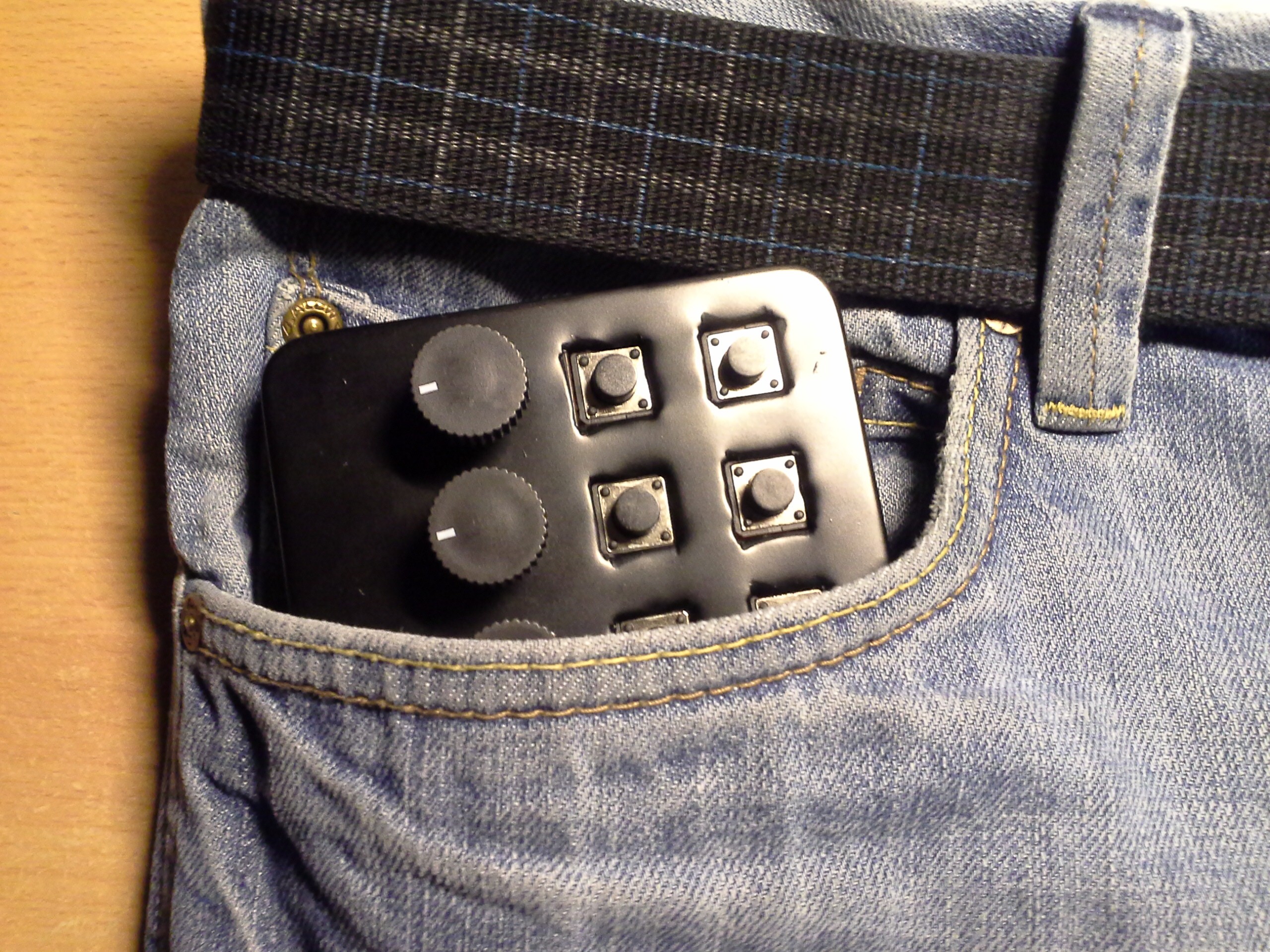
Pocketable: Check.
01/02/2015 at 22:39 • 0 comments![]()
A picture like this is a requirement for the contest, right? ;)
-
Schematic and code
01/01/2015 at 13:23 • 0 commentsI wasn't able to open the Eagle files for the Pro Trinket in order to add the buttons, rotary encoders and LEDs so I just made a schematic indicating the connections to the digital pins used by the Arduino IDE.
![schematic v2]()
This schematic and the final sketch can now also be found on the GitHub page.
EDIT 2015-01-16: Updated schematic to clarify connections.
-
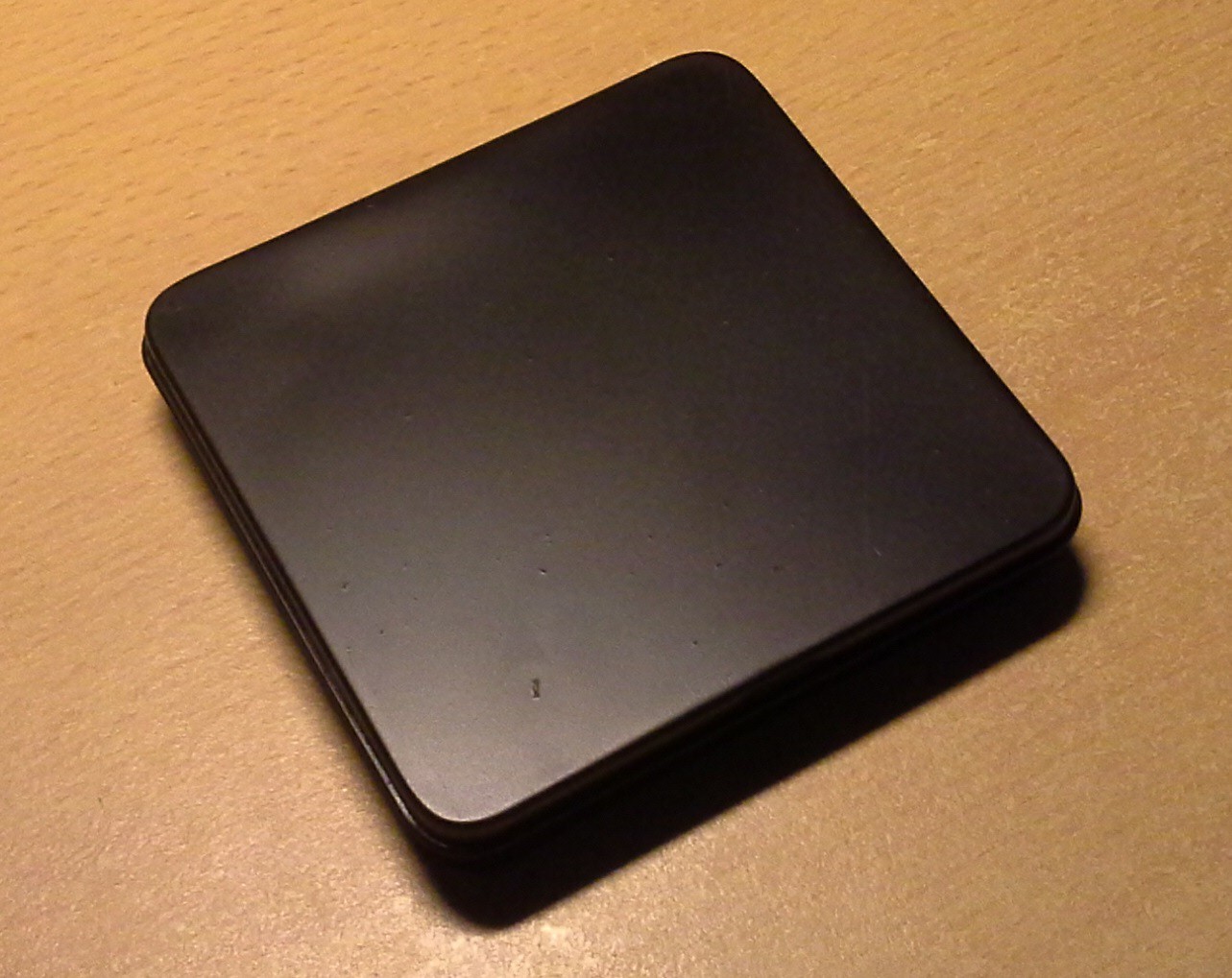
Case and assembly
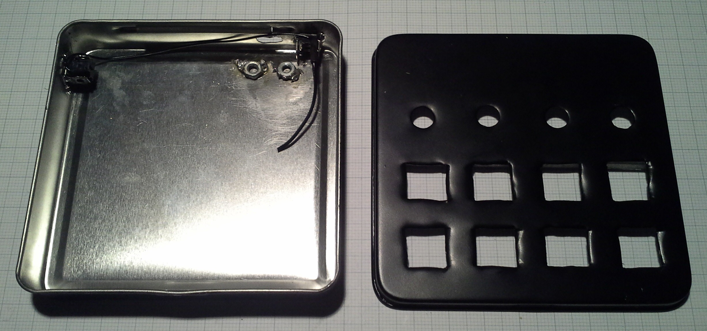
12/29/2014 at 21:45 • 0 commentsInitially I planned on building a very basic case out of two pieces of acrylic in the style of the Dangerous Prototypes Sick of Beige cases but then I picked up one of these mini cigar tins. (yes, that picture AGAIN)
![]()
It's about 92x89x18 mm so I figured it would be about the right size for the amount of buttons and would have enough space for the components.
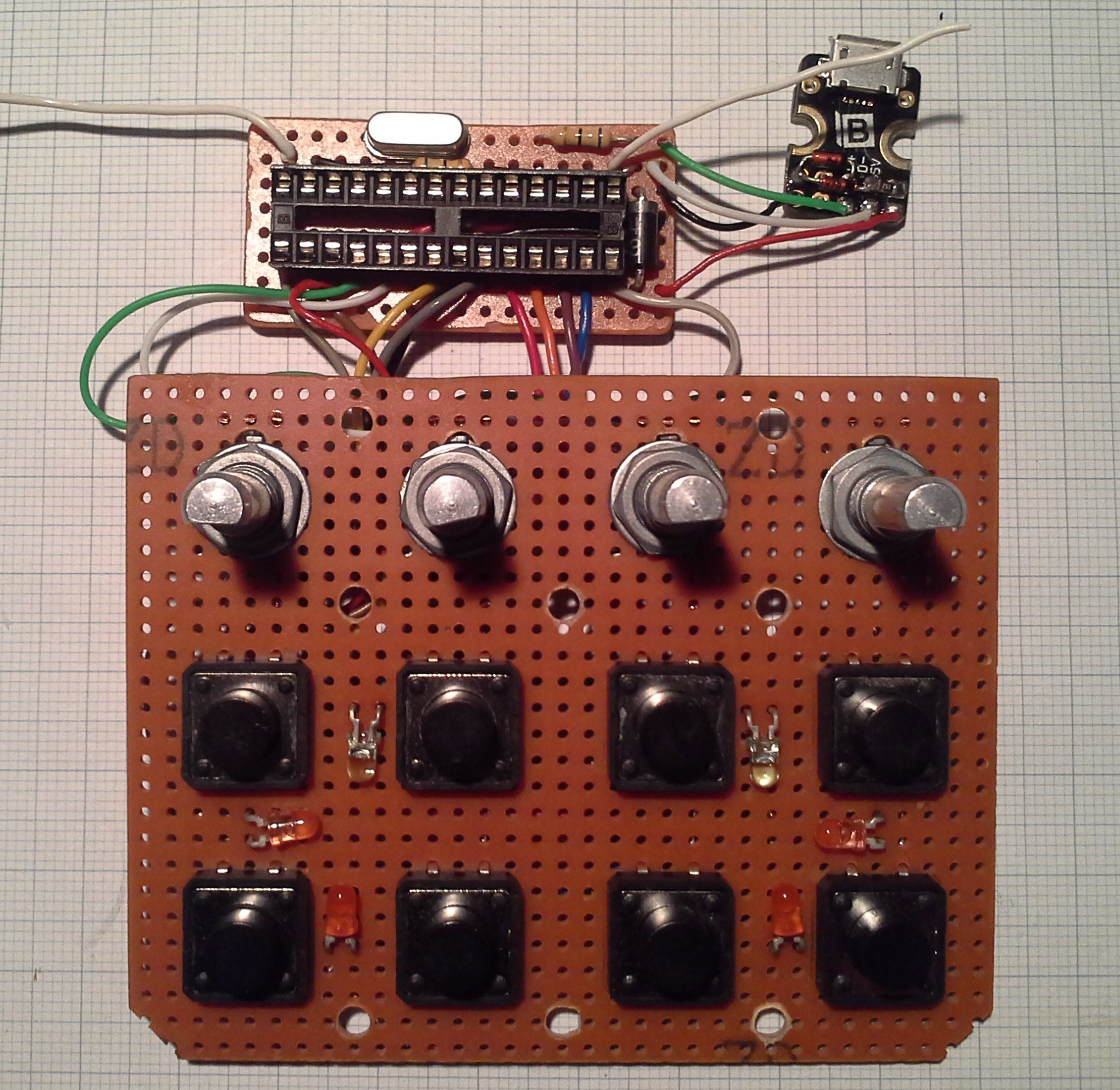
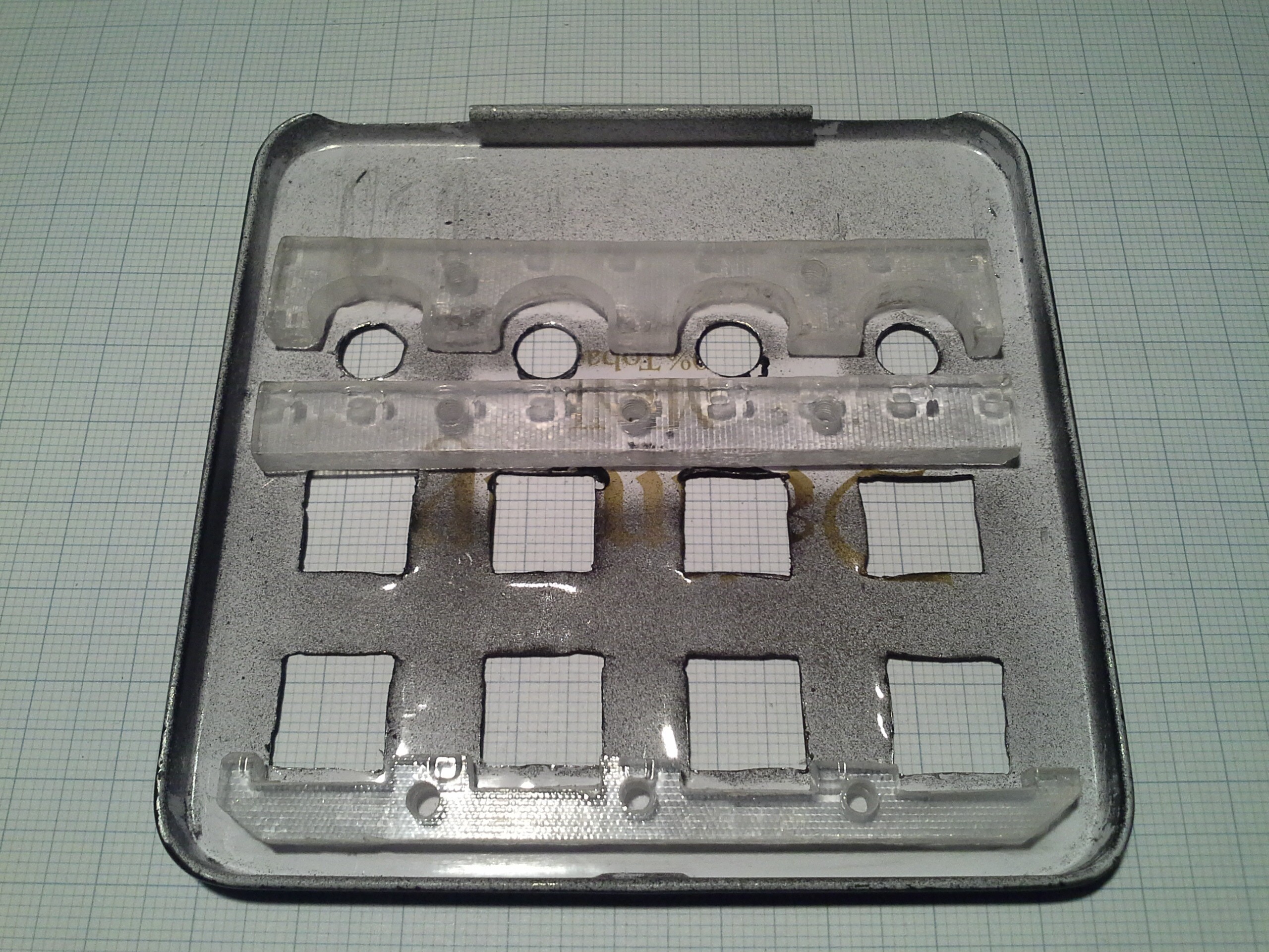
The idea was to mount the buttons and rotary encoders to a perfboard (as seen in a previous log) and mount that board to the lid of the case while the MCU and other components are mounted to the main body of the case. From the perfboard with the buttons and encoders I transferred the positions of the required openings to the lid and cut them out or drilled holes to the required diameter. Since the openings in the main body didn't have to fit precisely over buttons (and USB port) but instead the buttons could be aligned to the holes I just eyeballed those holes and ended up with this:
While with the lid I could simply cut the openings and paint it afterwards, the main body posed a bit of a problem. The heat from soldering the two switches to the case could damage the paint and painting the case after the buttons are in place could hinder the motion of the buttons. I ended up painting it first and then soldering the buttons and nuts (to fix the USB jack) at a lower temperature which made soldering a bit difficult and messy. But once the lid is closed nobody's going to care anyway ;)![]()
During test fittings I realized that I'd run out of space in the back of the case where the MCU should be placed. I would have liked the keyboard part to be detachable via some pin headers but to make it work I decided to permanently solder them together like this:
![]()
Due to these spacial constraints I had to omit mounting points for the MCU board as can be seen in the image of the bare case and the board itself. With the bottom of the perfboard isolated from the case with a sheet of plastic and the wires pressing against the board it is safely (enough) "mounted" in the case such that it won't move around.
Note: It might look like I'm missing some components for the Pro Trinket circuit such as filter capacitor, reset pull-up resistor and so on. To save space I used mostly SMD components and through hole where I wanted to bridge a longer distance. This time I even included the capacitors at the crystal ;) The two white wires are connected to the reset and mode buttons in final assembly.
Next I super-glued some spacers to the lid to which the keypad is attached.
![]()
The spacers are a little thicker than the body of the tact switches such that there will be a gap through which the backlight can be seen from the outside.
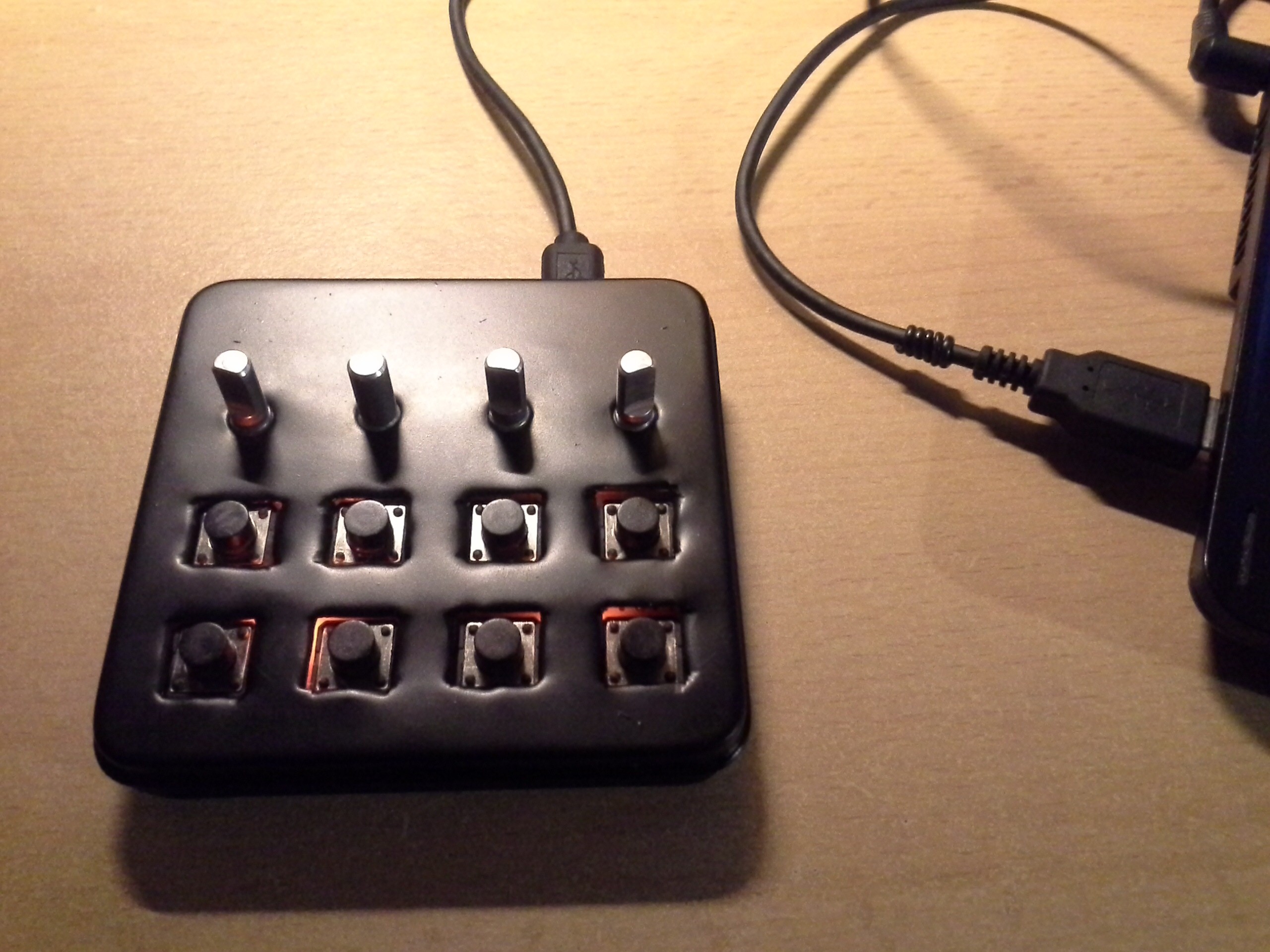
To finish it off the keypad is screwed onto the lid, the micro USB jack is mounted in the case and when closing the lid care is taken to keep the MCU board in place.
![]()
And that's it.
-
LEDs, cause... LEDs
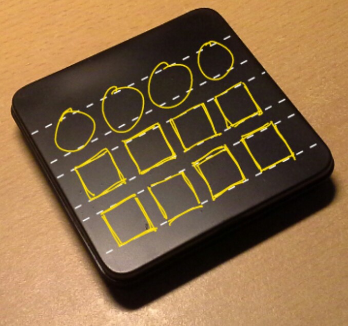
12/22/2014 at 19:28 • 0 commentsAs I mentioned before, I want to have multiple LEDs with different colors to indicate the currently active set of shortcuts. The idea came to me when I sent my friend this sketch of the layout:
![]()
Jokingly he replied that he'd like the yellow markings to be on the final device but I thought it might look cool if I put LEDs between the tact switches such that the light is visible from the outside between the lid and the switches. This is roughly how the LEDs are placed, with this pattern repeating in the neighboring 2x2 block of buttons (once it's done):
![]()
To keep complexity down I decided to drive 2 LEDs of the same color in series directly with a pin from the ATmega. This has some downsides (like limited current) but since the backlight is more of a gimmick I'm not going to spend a lot of time on it. On the other hand, an advantage of this is that the device won't draw a lot of current from the USB port.
The mechanism is pretty simple, just another button (yes another one, as if there weren't enough already ;) ) (the left one of the two non keypad buttons the other one is the reset button) to toggle through three LEDs (that are all green for this test).
![]()
For now I placed the button and LEDs on the next available pins (Arduino digital pins 15 to 18) but as mentioned before the pin assignment is subject to change such that the LEDs can be controlled with PWM and the wires going to the keypad end rotary encoders fit best into the case. Once the LEDs can be dimmed I'll play around with adding glowing/fading effects on key presses although I'm not sure if the LEDs I have are bright enough to be able to observe the effects even in the dark or if it would be distracting.
Regarding the code the button doesn't actually control the LEDs directly but changes a variable that indicates the current mode. Based on the value of this variable the arrays for the key codes are chosen and the pin for the corresponding LED(s) is set high. I'm not going to go into more detail on the code since polling of a button has been discussed before and advancing of a variable should be covered in basic tutorials better than I could do it here.
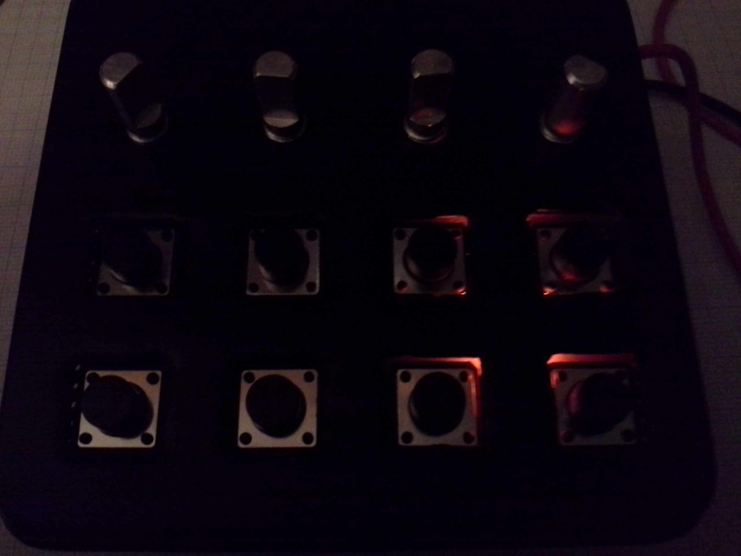
Over the weekend I worked a little on the case in order to be able to properly test this backlight but more on the case in a dedicated log. Therefore in order not to spoil too many details, here's a (intentionally dark) photo of one of the sides being illuminated:
![]()
-
Adding inputs: Bonus round!
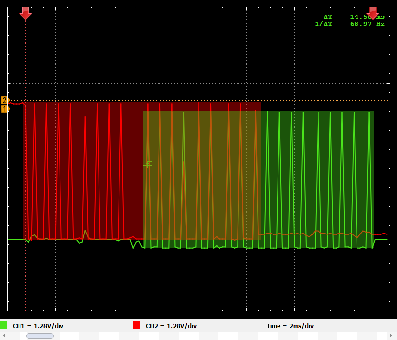
12/16/2014 at 19:42 • 0 commentsWhen I was talking about polling the keypad and rotary encoders in the last log, I felt like it might not become very clear for someone who is new to this. So I wanted to go into a little more detail and illustrate the issue a little better. To do this I probed the A and B outputs of an encoder while the Pro Trinket enables the input, revealing what the polling looks like:
(I know this is a pretty poor graph but it's the best my scope would do)
![]()
I intentionally offset channel 1 (green) and 2 (red) such that it would be easier to see the traces rising. Please ignore the beginning of channel 2, which should have started out in a low state. Yes, in the device the A and B signals are active low but for this example I wanted a high level to indicate the polling so I inverted the signals.
When the rotary encoder isn't actuated, both outputs/channels are in a low state... well, not in this image but let's just say they are ;) ... and when it is rotated the signals follow the outline indicated by the solid fill. Now we can finally get to the point: As mentioned before, the encoders aren't enabled the whole time but only momentarily to check the current state and this is what is indicated by the peaks (obviously when one encoder is disabled one of the other 3 is enabled). This test was to show that the rotary encoders are indeed sampled frequently enough to make a reliable decision about the direction.
It actually was quite difficult to produce such a short event, therefore I'm pretty confident that the encoders will work reliably.
Is this actually helpful or should I just stop complicating things ;)
-
Adding inputs
12/14/2014 at 18:22 • 0 commentsNow that sending of keystrokes over USB works as desired it's time to add the inputs. As mentioned before, the aim is to have 12 buttons (in a 4x3 keypad) and 4 rotary encoders.
Keypad
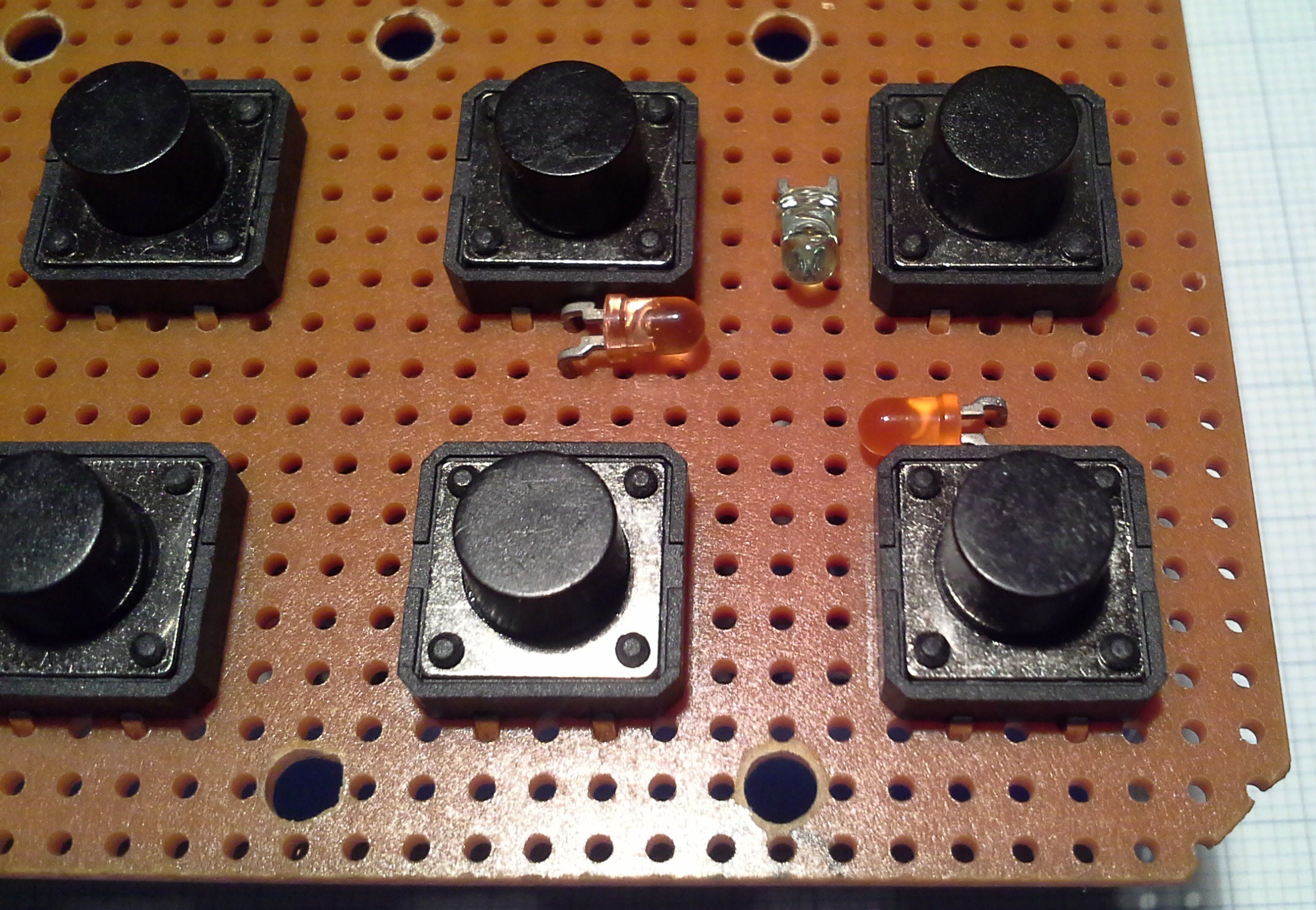
I'll be using encoders that also have a push button integrated. Those buttons will be part of the keypad but for prototyping I soldered up a dedicated keypad (out of whatever tact switches I had on hand).
![keypad]()
Via a quick search I found the Arduino keypad library that sounded pretty good since it would allow me to use 12 buttons with only 7 pins instead of potentially 12 pins. Initially I tested the library on a Pro Mini to be able to see output via the serial interface and it worked really great but when I tried it in combination with the VUSB for Arduino library I ran into trouble. Since the keypad library uses the delay function for software debouncing of the buttons, disabling timer0 for USB is problematic.
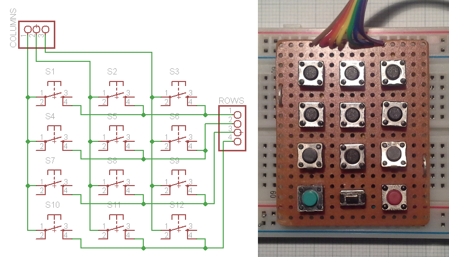
In an attempt to solve this problem I tried implementing this functionality myself. In case you don't know how it works, here's the basic gist: Only one column (e.g. column 1) at a time is set high while the others remain low. Now all the rows are read and if one or multiple rows are asserted (e.g. rows 2 & 3) this means that the corresponting button is pressed (in the above schematic for column 1 and rows 2 & 3 this would mean that buttons 4 and 7 are pressed). This is the basic version of how I did it:
(because I use the internal pull-up resistors these signals are active low which is the opposite of the small example)
//cycle through cols
for(int i=0; i<cols; i++){
   //enable col (active low)
   digitalWrite(colPins[i], LOW);

   //poll rows
   for(int j=0; j<rows; j++){
      //read state of current btn
      key_state[j][i] = digitalRead(rowPins[j]);

      //button is pressed, active low
      if(key_state[j][i] == 0){
         //execute keystroke
         UsbKeyboard.sendKeyStroke(usb_codes[j][i]);
      }
   }
   //disable col
   digitalWrite(colPins[i], HIGH);
}
// /cycle through cols
This will send a keystroke (corresponding to the key defined in the usb_codes array) every time the state of a button is evaluated as being pressed, which could potentially around 6000 times a second as discussed in a previous project log. Therefore a mechanism to only trigger a keystroke if a button is pressed but not when it's held is required. To do this I employ a variable to save the state of the previous button readings and one more condition as shown here:
key_state[j][i] = digitalRead(rowPins[j]);

//btn was just pressed, current state 0 prev state was 1
if(key_state[j][i] == 0 && key_prev[j][i] == 1){
   //set new prev state
   key_prev[j][i] = 0;

   //execute keystroke
   UsbKeyboard.sendKeyStroke(usb_codes[j][i]);
}
//key release
else if(key_state[j][i] == 1 && key_prev[j][i] == 0){
   //set new prev state
   key_prev[j][i] = 1;
}
Once a button is released the key_prev variable is reset and another button press can be recognized. In my test this worked quite well and felt very responsive so let's move on to the next part.
Rotary encoders
In another project with a rotary encoder I was just polling the two pins without using interrupts. Since it worked pretty good that's what I tried first.
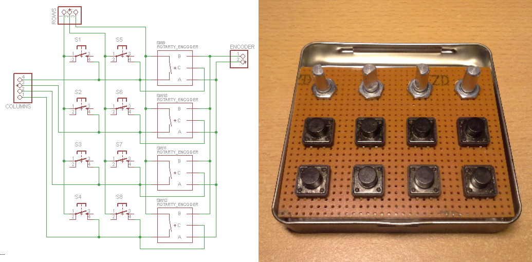
To implement the encoder polling into the previous code I followed the same principle as above and set it up to be active low (again, to utilize the internal pull-up resistors). That way I can use the signals that select a column to also select/enable one of the rotary encoders and detect on two additional input pins in which order the pins of the encoder go low. The order in which the pins are asserted of course corresponds to the direction in which the encoder is turned. Incorporating the 4 rotary encoders into the keypad then looks like this:
![keypad_final]()
And here's the code to make it work:
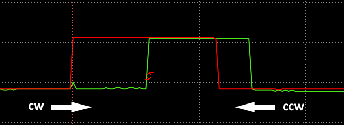
//poll encoder
int A = digitalRead(encPins[0]);
int B = digitalRead(encPins[1]);

//detect rotation
if(A == 0 && enc_prev[i] == 1){
   //change prev state
   enc_prev[i] = 0;

   //determine rotation direction (cw/ccw)
   if(B == 1){
     //cw rotation ...orwhatever?

     //execute keystroke
     UsbKeyboard.sendKeyStroke(usb_codes_enc[i][0]);
   }
   else if(B == 0){
      //ccw rotation

      //execute keystroke
      UsbKeyboard.sendKeyStroke(usb_codes_enc[i][1]);
   }
}
else if(A == 1 && B == 1){
   //no input on encoder pins
   enc_prev[i] = 1;
}
// /poll encoder
What this does is it looks at one of the two encoder outputs and once it is asserted (remember, active low therefore A == 0) it evaluates the other output. Depending on the direction of rotation, if one of the two outputs (e.g. A) is being asserted, the other one will either still be not asserted (B == 1) or will already have been asserted (B == 0). To understand this it helps to look at the output of a rotary encoder:
![rotaryEncoder_waveform]()
Here the horizontal axis is the time and the vertical axis the signal. The direction of rotation then corresponds to moving through the traces either left to right or right to left.
The Adafruit Trinket USB volume knob project (which I kept in mind in case my approach wouldn't work out) uses a similar mechanism but employs direct port access for better performance which I didn't find necessary in terms of responsiveness.
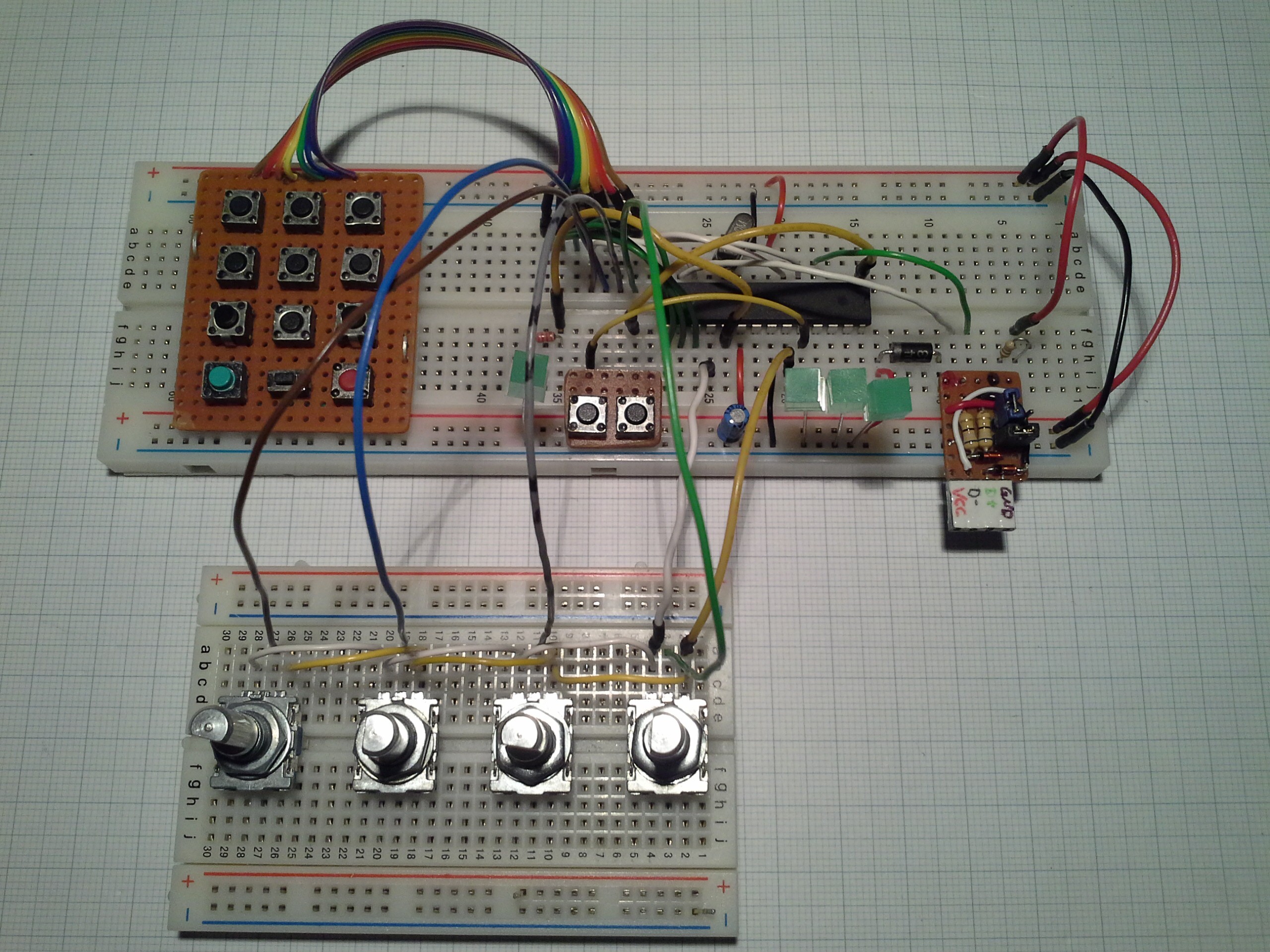
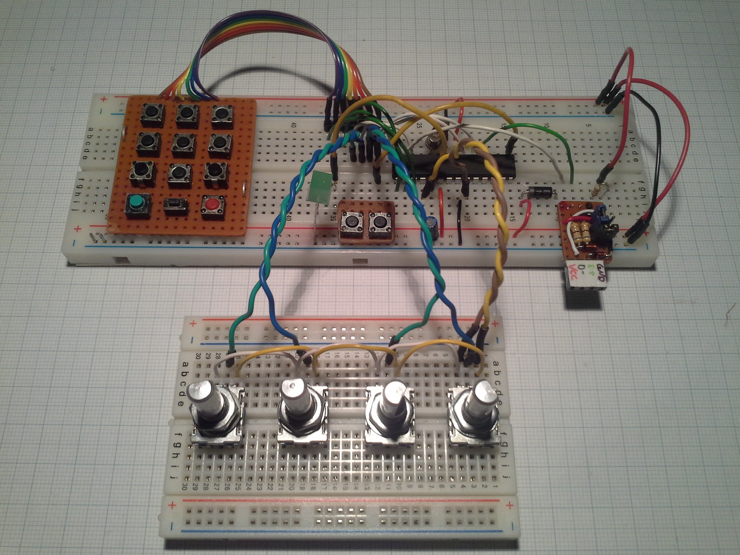
And this is what it looks like with the keypad and rotary encoders attached:
![]()
Note that I still use all the buttons on the keypad instead of substituting one column by the switches in the encoders. I don't think it will make much difference and this way I saved some wiring that would make it more confusing.
The 3 pairs of twisted wires actually worked quite good, while keeping the encoders in contact with the breadboard was somewhat problematic. It was only when I probed the A and B outputs that the twisted wires distorted the signal.
Concluding remarks
I hope this explains sufficiently how the keypad and rotary encoders work in this system. I'm somewhat hesitant to post the complete code since it's not really optimized and has some redundancies that would make it harder to follow what's (supposed to be) going on. Quite often I only find parts of projects helpful and am not interested in replicating the whole so hopefully you can use this information in your (maybe USB unrelated) project. However, once the code is done I'll definitely post it.
The same goes for complete schematics. I plan on changing the pins a bit to free up PWM capable pins for LEDs. Since this isn't using interrupts you can use whatever pins are available, it should be pretty straightforward.
Another thing regarding the usage of interrupts is that it might be more reliable for the keypad and especially for the rotary encoders but since the purpose of this device is translating key presses into USB and the responsiveness of it is quite good I'll stick with polling the inputs for now.
-
Project status as of dec. 5th
12/05/2014 at 22:40 • 0 commentsJust a quick update:
Currently I have the keyboard with 12 buttons and 2 rotary encoders working on a breadboard. I'm waiting on some tact switches and rotary encoders but the two missing encoders are polled nonetheless and should work when put in place.
As mentioned previously, I want to add a button that allows to switch between multiple different sets of keyboard shortcuts. Polling another button to do that should be pretty straight forward.
Pro Trinket USB Keyboard
A USB keyboard for custom shortcuts based on the Pro Trinket and Pro Micro