-
LVDS - VESA / JEIDA
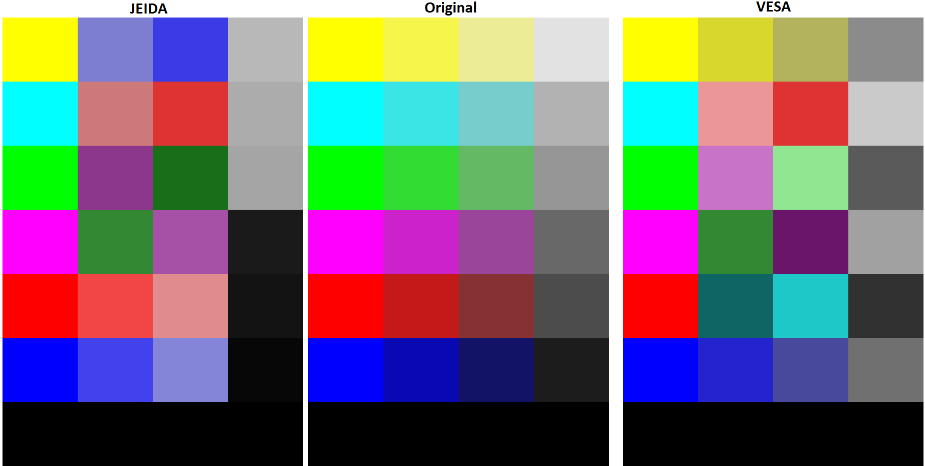
09/06/2016 at 17:58 • 0 commentsThe LG display allow to select the LVDS mapping between JEIDA and VESA. I encountered such issue again and images were generated to help diagnose the issue.
![]()
The original image is pass through the conversion mapping to obtain the VESA and JEIDA images.
VESA to JEIDA JEIDA to VESA JEIDA VESA JEIDA VESA B2 B0 B0 B6 B3 B1 B1 B7 B4 B2 B2 B0 B5 B3 B3 B1 B6 B4 B4 B2 B7 B5 B5 B3 B0 B6 B6 B4 B1 B7 B7 B5 G2 G0 G0 G6 G3 G1 G1 G7 G4 G2 G2 G0 G5 G3 G3 G1 G6 G4 G4 G2 G7 G5 G5 G3 G0 G6 G6 G4 G1 G7 G7 G5 R2 R0 R0 R6 R3 R1 R1 R7 R4 R2 R2 R0 R5 R3 R3 R1 R6 R4 R4 R2 R7 R5 R5 R3 R0 R6 R6 R4 R1 R7 R7 R5 Original BMP Images :
-
HDCP / HDMI Color Space
08/19/2016 at 02:32 • 0 commentsI got a Chromecast and I was disappointed when no image was displayed on screen. The Chromecast enables HDCP which the HDMI to LVDS controller doesn't support.
I have bought a HDMI splitter in order to overcome the HDCP issue. The display has some issue with the splitter. The screen doesn't display an image when connected directly to the splitter. When doing Splitter -> Selector -> Screen the display show a image correctly from the computer but the image from the Chromecast has a purple tint. Some article on google talks about the hdmi color space being invalid 4:4:4 YCbCr vs 4:4:4 RGB.
Test performed on the HDMI splitter :
- 2ch audio : ok
- DTS and AC3 : not supported but advertised. I tested with 2 systems, a regular HD-TV with AC3. AC3 is not available thru the splitter
- performance : unit gets really warm. There is an LDO inside, terrible efficency. Consums 300mA.
The unit doesn't take into account the screen configuration. I have a display that only support RGB 4:4:4. My computer displays fine but not the Chromecast.
The issue would be more color space related than HDCP related. The Chomecast is able to display correctly on a HD-TV. The same HD-TV reports HDCP as not supported under the audio properties.
-
PIC16F1455 Programming
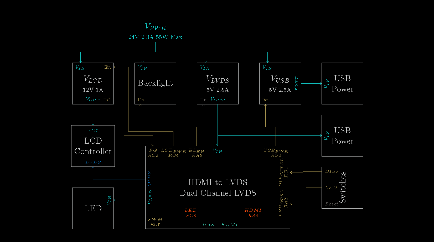
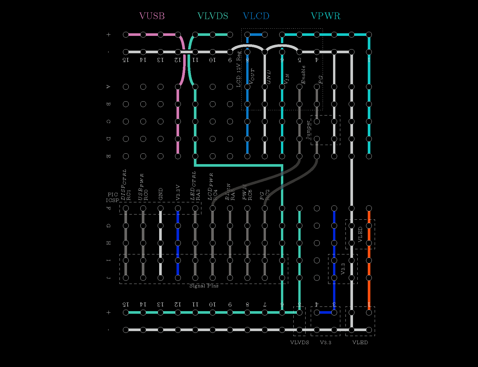
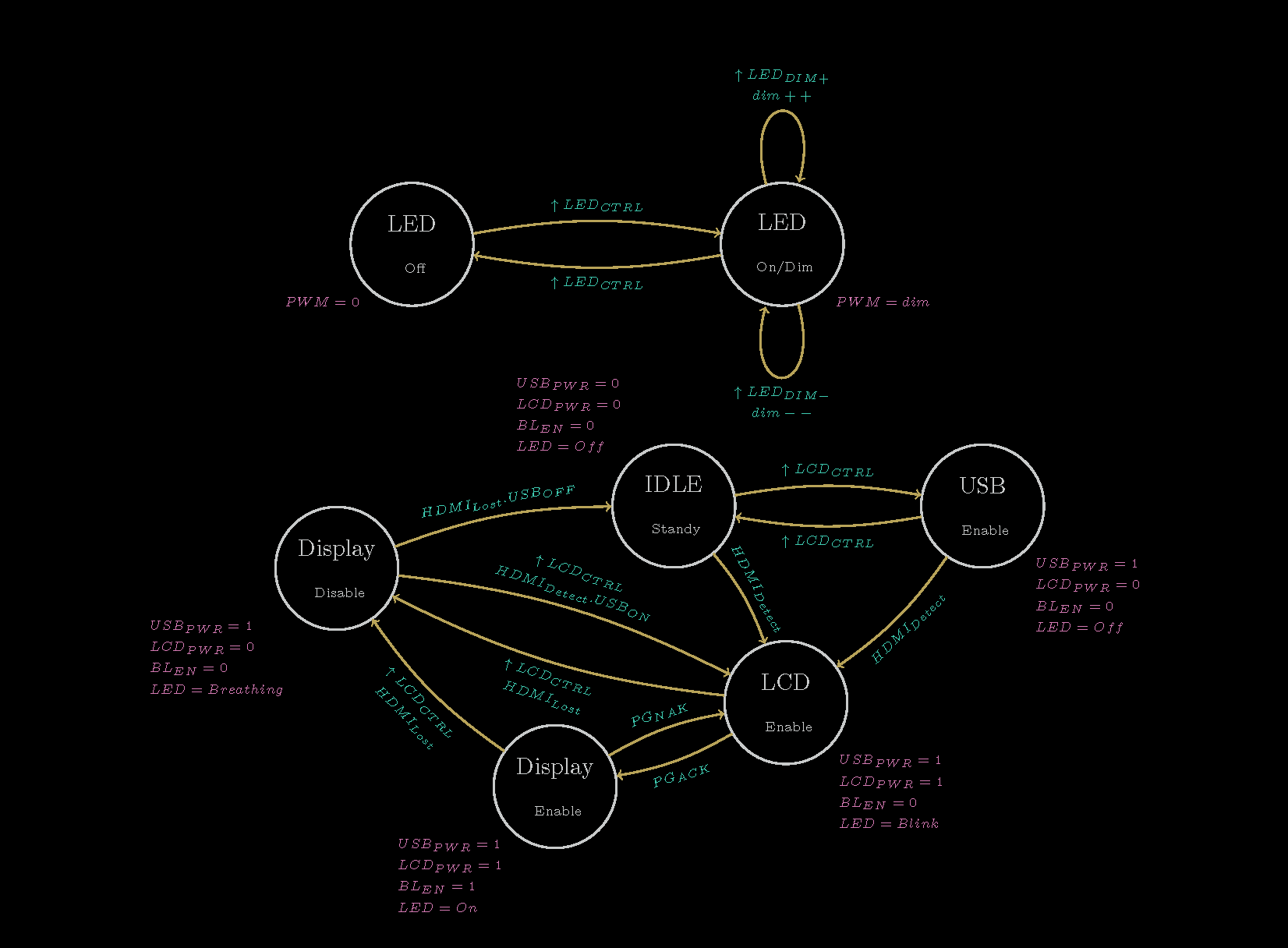
08/09/2015 at 23:55 • 0 commentsBefore doing the programming of the onboard PIC microcontroller, I made a LaTeX documentation of my system so I can easily refer to it and update it as I code. I change some pin assignment due to the PIC IO limitation. The RA3 is an example, the pin is input only therefore I connected it to one of my push button. The USB PIC16F1455 Breakout Board was very useful to test and debug my programming prior flashing my TV.
![Schematic]()
![BreadBoard]()
![System State Machine]()
In order to perform tests during my development, I setup a test bench with my BusPirateV4. I wrote a BASIC script to easily generate my test signals. With my test system behaving as I wanted, I flashed the onboard PIC. The display can now be turned On/Off, put into standby. The control of the 5V USB power regulator allow to power up the Raspberry PI. The USB power regulator will be turn off when no signal is detected from the HDMI and the USB serial connection is not active. The USB serial connection allow to control the screen from a terminal. The USB and Display output can be over-written. The LED is also controlled and dim via the serial.
10 PRINT "Setting IO ..."
11 LET D=255
13 PRINT "HDMI    <> MOSI"
14 LET D=D&254
15 PRINT "LCD PG  <> CLK"
16 LET D=D&253
17 PRINT "LCD PWR <> MISO"
18 PRINT "USB PWR <> CS"
19 PRINT "D=";
20 PRINT D
21 SEND D
22 PSU 1
23 PRINT "Done"

30 PRINT "Menu :"
31 PRINT "1-HDMI"
32 PRINT "2-LCD PG"
34 PRINT "3-END"
35 PRINT "4-Loop Test"

50 GOSUB 3000
51 LET H=(R&1)
52 LET P=(R&2)/2
53 LET L=(R&4)/4
54 LET U=(R&8)/8
55 PRINT "HDMI    : ";H;" LCD PG  : ";P
56 PRINT "LCD PWR : ";L;" USB PWR : ";U
57 INPUT "Select",S
58 IF S=1 THEN GOTO 200
59 IF S=2 THEN GOTO 300
61 IF S=3 THEN GOTO 1000
62 IF S=4 THEN GOTO 400
63 IF S=5 THEN GOTO 500
64 GOTO 30

200 PRINT "HDMI value"
201 GOSUB 2000
202 PRINT "HDMI Set to ";V
203 LET V=V&1
204 GOSUB 3000
205 LET R=R&254
206 LET R=R|V
207 PRINT R
208 SEND R
209 GOTO 50

300 PRINT "LCD PG value"
301 GOSUB 2000
302 PRINT "LCD PG Set to ";V
303 LET V=V&1
304 LET V=V*2
305 GOSUB 3000
306 LET R=R&253
307 LET R=R|V
308 PRINT R
309 SEND R
310 GOTO 50

400 PRINT "Test PG"
401	FOR B=1 TO 10
402 LET M=253
403 LET V=2
404 GOSUB 4000
405 PRINT B;"PG (1)"
406 DELAY 5000
407 LET M=253
408 LET V=0
409 GOSUB 4000
410 PRINT B;"PG (0)"
411 DELAY 2000
412 NEXT B
413 GOTO 50

500 PRINT "Test HDMI"
501	FOR B=1 TO 10
502 LET M=254
503 LET V=1
504 GOSUB 4000
505 PRINT B;"-HDMI (1)"
506 DELAY 5000
507 LET M=254
508 LET V=0
509 GOSUB 4000
510 PRINT B;"-HDMI (0)"
511 DELAY 2000
512 NEXT B
513 GOTO 50

1000 PRINT "All Off & Input"
1001 SEND 0
1002 SEND 255
1003 PSU 0
1004 END

2000 PRINT "1-ON"
2001 PRINT "0-OFF"
2002 INPUT "Value",V
2003 RETURN

3000 LET R=RECEIVE
3001 PRINT "R : ";R
3002 RETURN

4000 LET R=RECEIVE
4001 LET R=R&M
4002 LET R=R|V
4003 SEND R
4004 RETURN
-
Finishing Display
04/12/2015 at 04:26 • 0 commentsFrom the first work some improvements could be made and other had to be done.
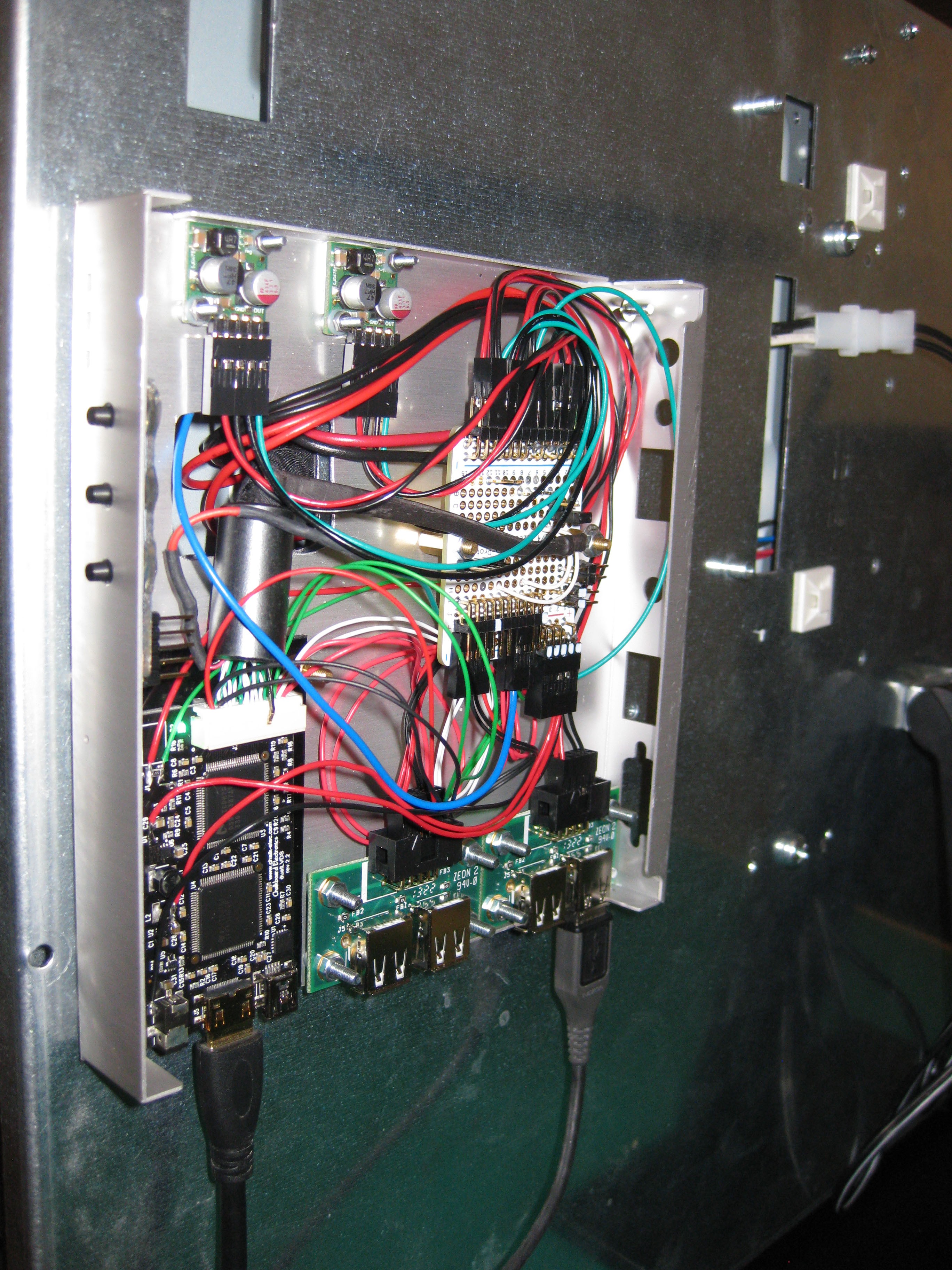
The cabling had to be redone so the screen could be usable and easy to handle. I found a nice aluminum box on mini-box.com the case1c1. That box is cheap and has correct size. What's going in the box :
- The HDMI to LVDS converter
- Step Down voltage regulators
- A pair USB output for power
- Push buttons
I added another 5V Step down power supply for another pair of USB output. The goal is to control those USB to turn on or off the RasPI or other devices such as USB Powered Speaker.
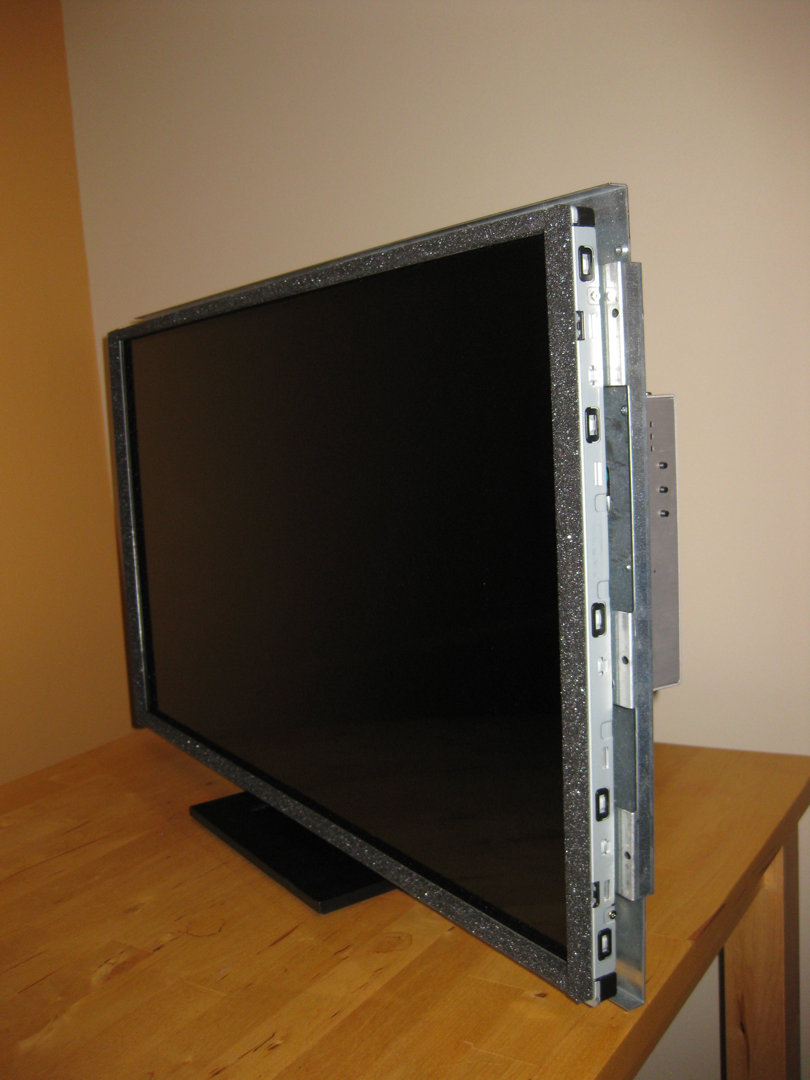
The display is supported by a DELL stand. It works quite nicely, the screen is able to tilt back and forth.
The power supply is mounted on the back panel, just need a power cord and an HDMI to enjoy a movie.
The push buttons are not yet active, the PIC16F1455 needs to be reprogrammed to handle them. The PIC16F1455 will also act as a Virtual Com Port to control the screen via USB.
Box wiring
Back Panel
Display and side control
LD320EUN 32" Display for RasPI
I salvaged a LD320EUN 32" Display without any connection. The Project : make it a display monitor
 Stanislas Bertrand