Close
0%
0%

Swifty's Relay Clock Project

24 hour clock made with relay logic

Similar projects worth following
When I saw Dave Gönner's Relay Clock the gears in my head immediately started turning. I loved the overall concept, idea and application. I wanted to have one too - with some additional features/improvements that I thought would be handy made with the tools available to me.

Relay Logic is neither something new or very complicated on this scale and a rather similar project from Dave Gönner is also already online (even though never completed), so why bother?!

Simple answer:
I wanted one for myself and the project lets me optimize my multi-PCB workflow that I will reuse for another relay-less project. So in the end I will not need to develop an extra prototype PCB. It was also the first time I ordered from a well known Chinese PCB supplier that I wanted to try out before I throw more money at it. 

I hope you like my realization of the relay clock. Files will be put online soon, so please be patient. At the moment I am already soldering the first PCBs together, so this should be done soon.

RelayClock_simple.ino

Source Code for the ESP

x-arduino - 9.76 kB - 01/02/2019 at 08:03

Download

  • 76 × FTR-B4CA 12V Switches and Relays / Electromechanical Relays
  • 288 × UF4003 Discrete Semiconductors / Diodes and Rectifiers
  • 106 × LL 0805 WS SMD LED 120° White
  • 4 × A0 3418 N-CH Mosfet 30V, 3.8A
  • 1 × LM1117 MPX-ADJ Power Management ICs / Linear Voltage Regulators and LDOs

  • Working Clock hanging on the wall

    SwiftyTheFox00105/03/2018 at 19:32 3 comments

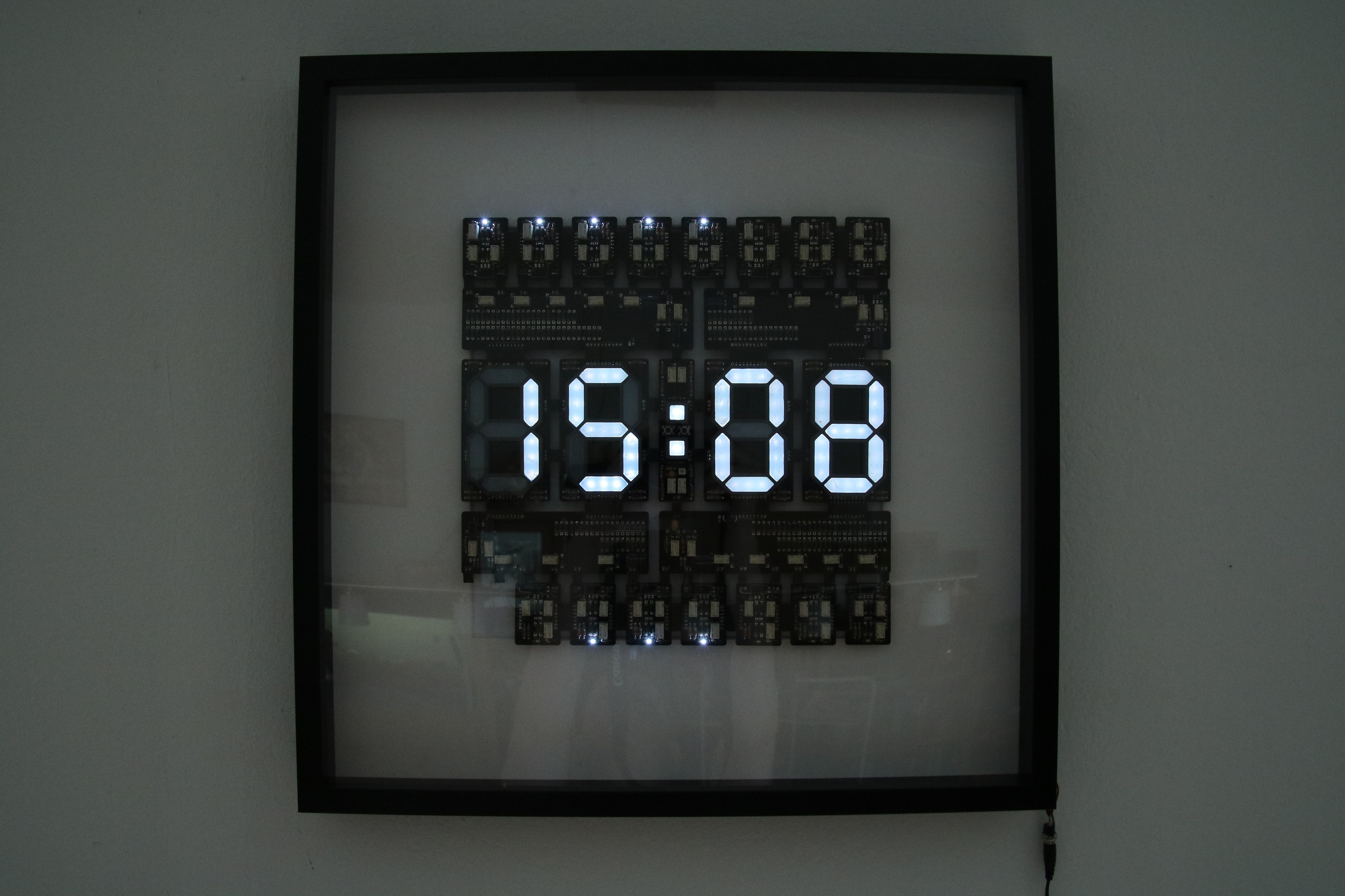
    ITS DONE!

    Final Clock on The Wall
    Yes, these are my hands...

    The ESP is sitting on the back doing its job getting the time for several days now. I slightly altered the NTP protocol example within Nodemcu's arduino library. The dots are only blinking after a reset to indicate WIFI and NTP status.

    I even added a last minute feature: A daylight saving time jumper that chooses the right UTC offset after resetting the clock. Yes, I could have written a smarter code that checks if it is time to switch, but I was too lazy. I don't want to poll any sites regularly as well for parsing this information, so resetting should do it for the moment until I come up for a better idea.

    Stuff that is still on the todo list for when I am bored by other stuff:

    • Printing a PSU barrel plug holder for the frame - it just looks ugly at the moment.
    • Writing a better program that is going into deep sleep for most of the time to save power.
    • Using even higher serial resistors for the FlipFlop-LEDs. They are way too bright :)
    • Finding a good use for the empty FF slot.

    The promised video is missing as well and I might post more about the way I did the diffusors for the seven segment displays. They did not end up as smooth or easy as I intended, but I am still happy with the outcome. 

  • Relay PCBs + Digits finished

    SwiftyTheFox00104/23/2018 at 11:51 0 comments

    Last Friday my last PCB package with the updated "dots" section and slightly modified "digits" finally arrived.

    After some bug fixing the whole clock worked flawless when clocked with the built in buttons. The MOSFET drivers with the relays for switching functions (RESET, CLK1&2, ADJ) via an external source work fine as well. Bigger MOSFETs could have replaced the Relays in general on this sections, but this was not the intended way of this project, wasn't it? :)

    The thing that cost me most time was the LM1117 ADJ - it seems that I have chosen too large resistances because the curve was so much off, that I was more successful by trying out some combinations instead of calculating it. Yes, I was designing it at first with 1,25V between the adj pin and gnd, but the newly calculated resistor values should have been working.

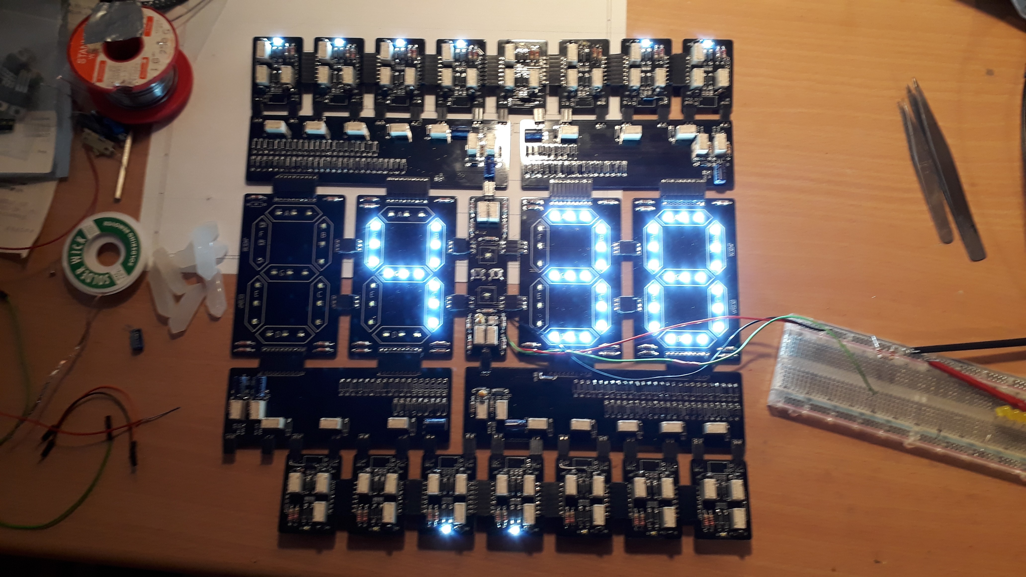
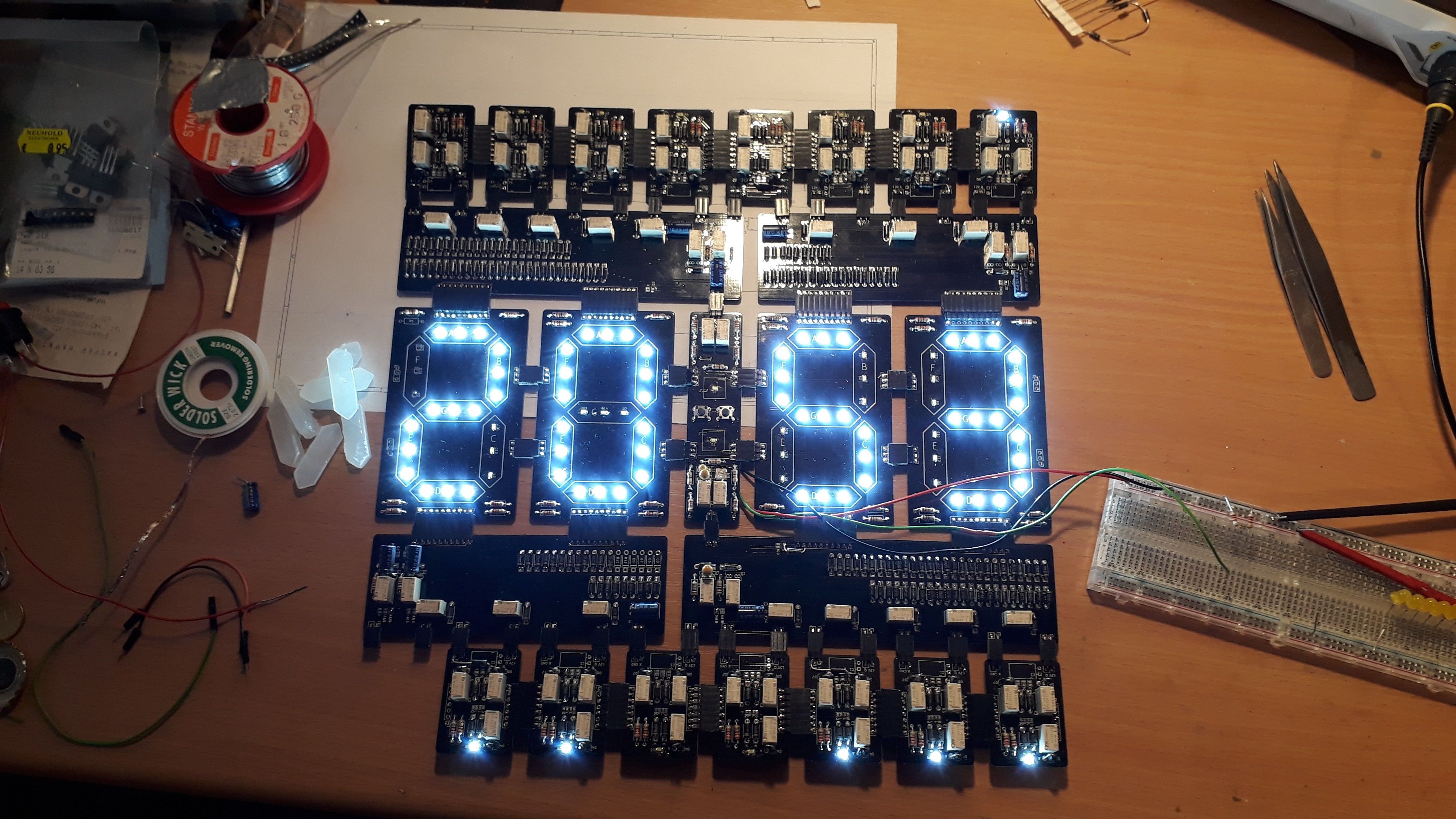
    Here are some pictures:

    Clock Demo 4:38
    Everything working - clocked with buttons in center. Hour-ten's are dark if 0 as intended.
    Clock Demo 20:53
    Just another demo of the clock with the hour-ten's showing a digit as well.

    A video is following up once my clock source is operational and the diffusors are in place. You can see the diffusors already lying right next to the clock, they are looking promising with the lower ADJ voltage set. The full 12V are a bit too bright... Maybe I'll change the resistances once more before I put the clock on the wall.

  • The Clock Pulse Circuit

    SwiftyTheFox00102/23/2018 at 10:53 0 comments

    Some of the PCBs got lost on the way, but the the decoders and the flipflops work fine. Nonetheless, the project is on hold until they arrive.

    I even added some zener diodes to save my LEDs from frying- they suffer from reverse voltage kills thanks the relays. Never thought that the peaks would ever be that huge....

    To do at least something I thought that it might be worth it to write a wrap up about my decision to add a A&!B-Gate to every Decoder. The use seems a bit redundant for all non-resetting decoders, but there is a reason to it.

    How the clock is carried over in TTL / CMOS

    The easiest way to connect one johnson counter to another in a TTL/CMOS world to the other would be to connect the Q (falling clock trigger) or !Q (rising clock trigger) of the most significant FF in the lower stage (faster counter) with the clock of the higher stage (slower counter).

    The troubles with the used relay logic
    The problem with the existing FF design is, that active outputs deliver an active low (0V) and that the clock signal needs to be 12V -> high. This alone would require a relay to invert the signal. The other thing is, that a very long active high clock consumes #FFx10mA since there is always one of the two input relays closed per FF for a CLK high. 

    And there is even one more reason to keep the clock signal tristate (not low!) as long as possible: 
    There are 3 possibilities when a clock signal between counters is active high: ticking (only lowest clock driven by uC), manually setting (2 buttons between dots) and autosetting via the uC. There are several combinations when a clock is set high via the carry-over of a lower stage, neither setting it manually or via uC would work, since something that already is high cannot generate a rising flank.

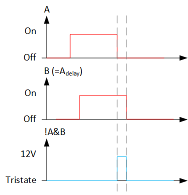
    So what was needed was a monostable circuit that generates only one pulse for every input flank. So Q low -> Q tristate would end up in a short "clk tristate - clk 12V - clk tristate".

    The design solution
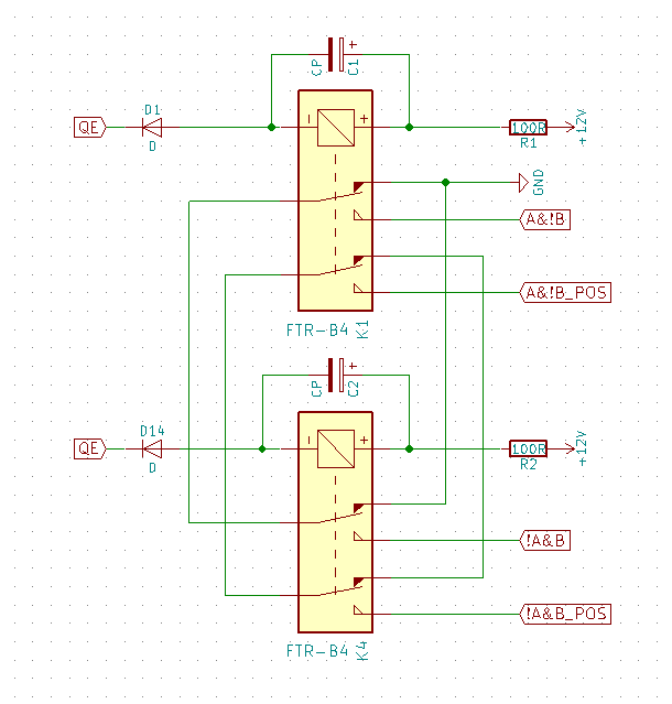
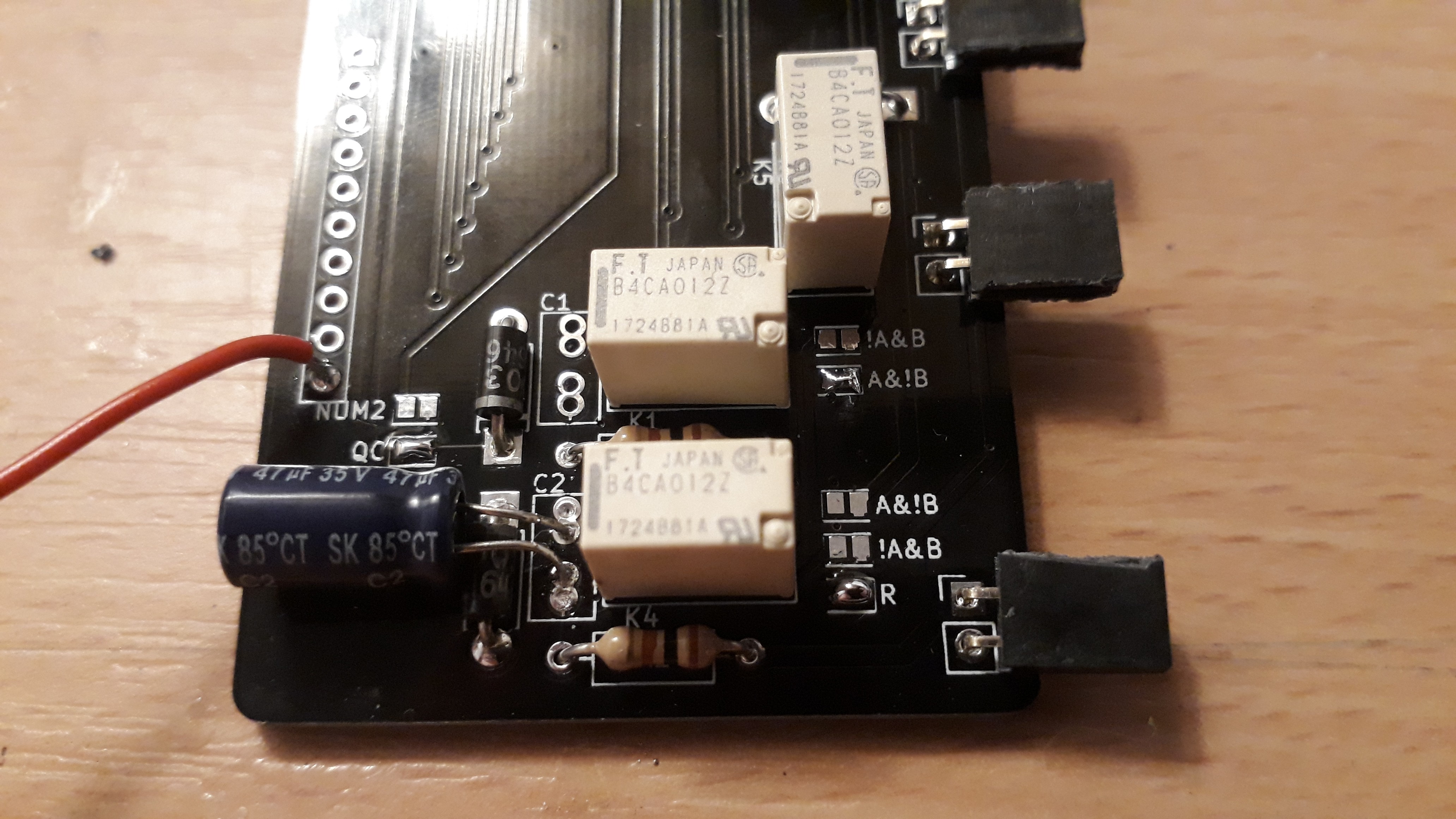
    Thanks to the original design from Daniel we have AND gates with A&!B and !A&B Outputs at hand. Using the Q on both inputs and delaying one input generates exactly what we want - a pulse. The delay is easily achieved with a cap and a serial resistor. The resistor is capped by the setting voltage of the relay (9V), but luckily we don't need a very long pulse (setting time ~3ms) so I sattled with 100R and 47uF. 10uF was not enough unfortunately.

    A&!B Relay Gate
    Schematic of the gate including 0V/12V inverted/noninverted outputs and optional delay caps
    Clock Pulse Signal
    Thanks to the delay the Gate generates a short pulse long enough to trigger the clock

    Small detail: I planned the inverted output option in in case I would mess up - and I did. But luckily this means now only soldering another jumper bridge together to work. In the video in Log 2 you can see the effect - it generates a pulse at "2->3" and not at "5->0". Fricking inverted logic levels...

  • Changes, Reconsideration and Bugs

    SwiftyTheFox00102/21/2018 at 09:16 0 comments

    Current Consumption
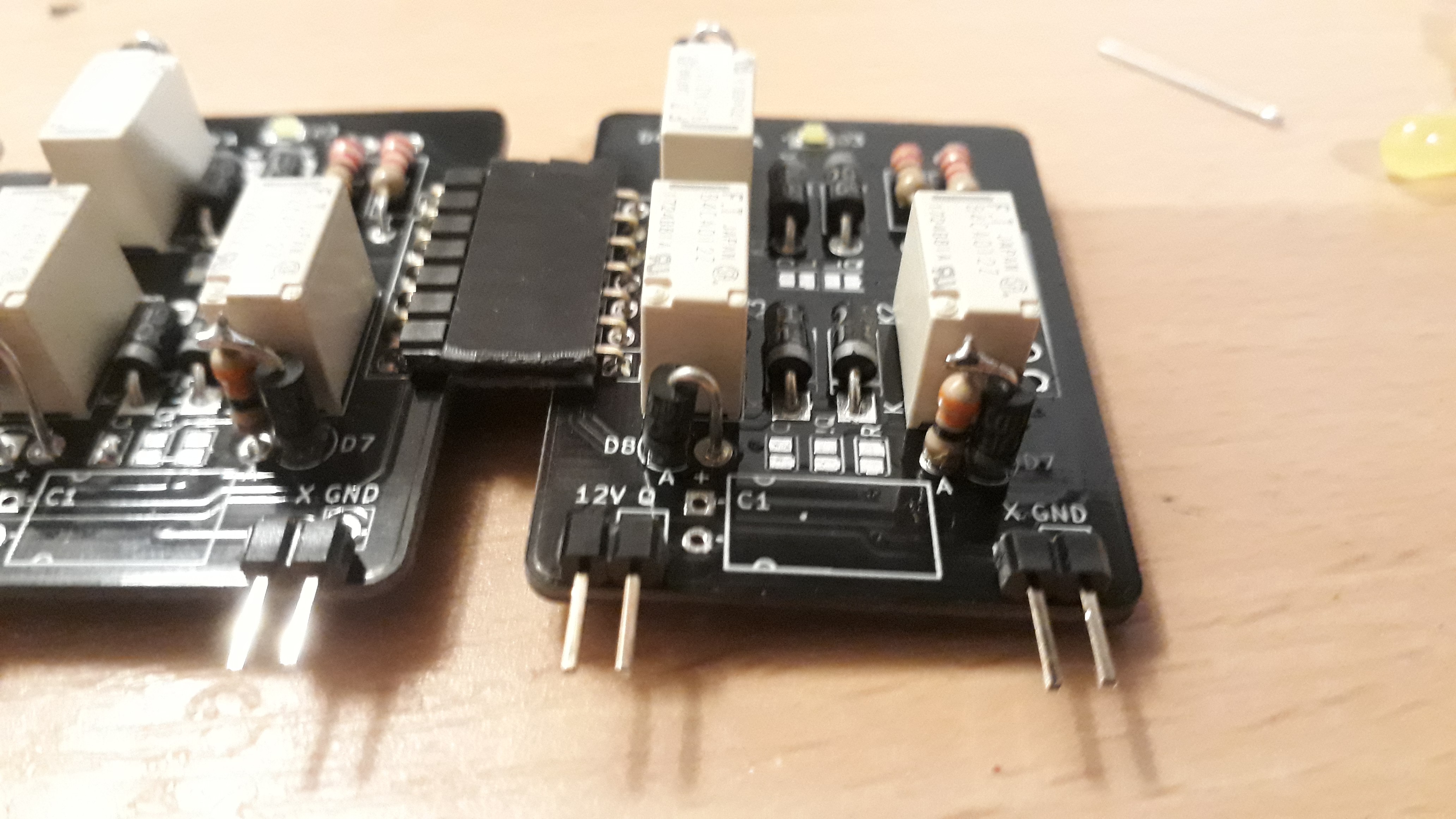
    During soldering together and testing the first FF's I got the idea to reduce the current consumption of the whole clock AND to keep the LED's on the FF's. The LEDs I use are still damn bright when used at 1/5th of Ifmax, so the easy fix was to increase the serial resistor to 2k2. The thing that bothered me more was the reset current. The current during reset is only limited by a 220R Resistor and a Diode - so roughly 50mA@12V. Multiply this with 15 (all FF's) and we get a whooping current consumption of 750mA - just for the reset pulse. A serial resistor between the 220R and the Diode D7 (Reset) would reduce this. The limiting factor here is the reset Voltage of the Relays: 1.2V. I also found a beautiful way to retrofit them on the FF's - I just mounted them next to the vertical Diode D7:

    Vertical Mounted Diode together with current limiting resistor
    Vertical Mounted Diode together with current limiting resistor

    I went with 100R first, setting the reset Voltage to 4.16V@35mA, but Some Relays did not reset properly - like it is written in the spec. So some Relays got 33R instead. This means that I am not getting the way better reset current of 525mA thanks to some relays, but it is for sure better than what I had before. If I encounter problems due to a too high voltage drop over the reset line, I'll just reduce the resistor again for the problematic relays.

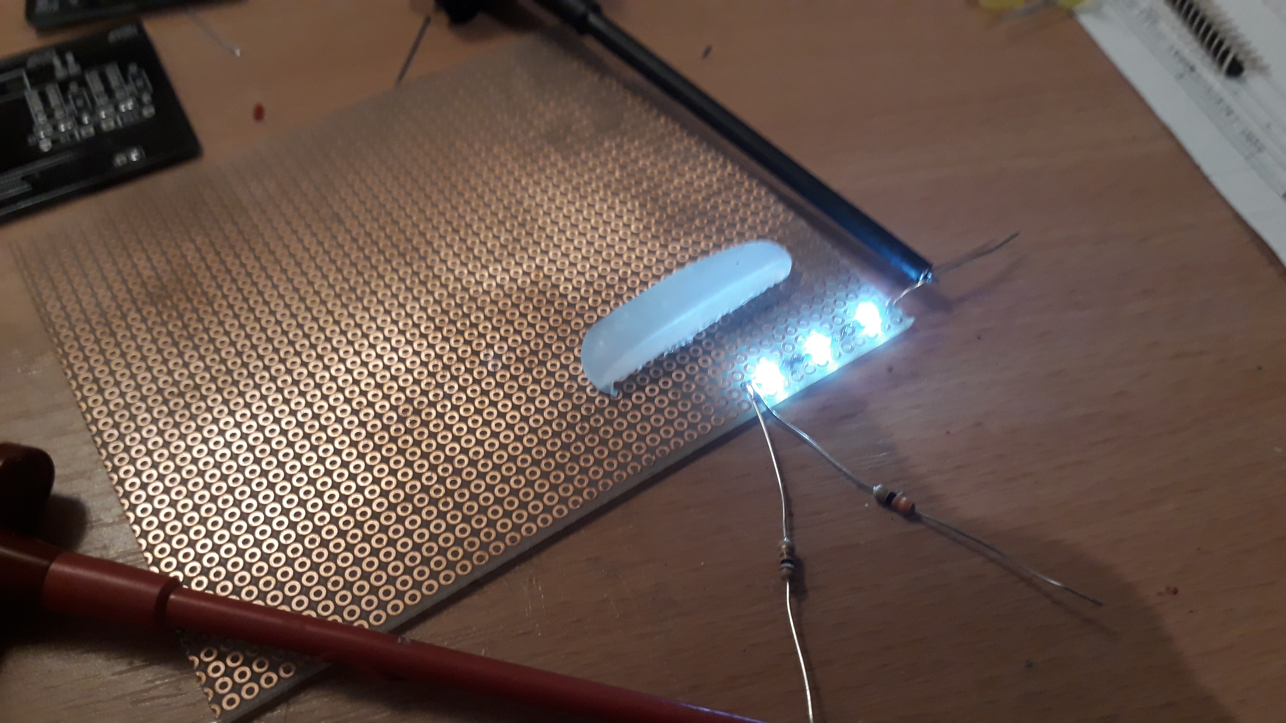
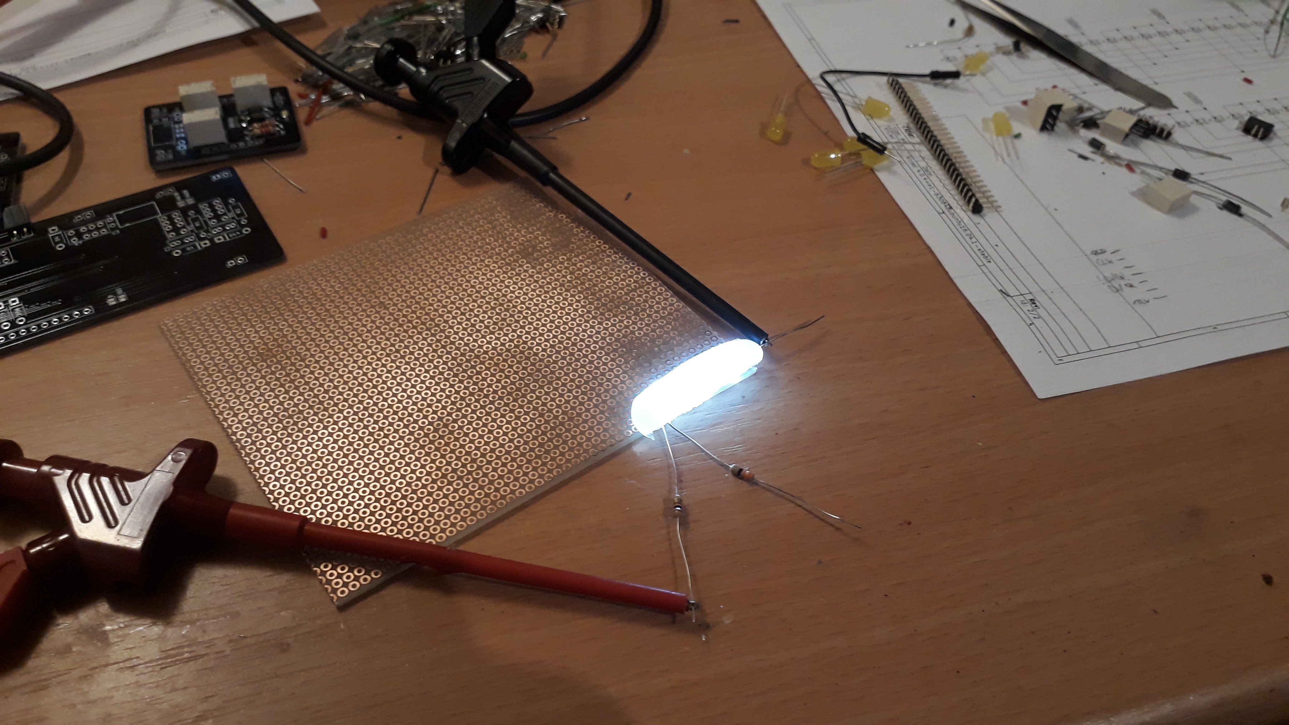
    I also played around with the dummy hot glue diffusor I made. Reducing the current to the half does not change anything here as well and is still readable during daylight.

    3 Leds without Diffusor...
    3 Leds without Diffusor...
    ... and with a hot-glue diffusor
    ... and with a hot-glue diffusor

    The sum of these changes will reduce the electricity cost for this clock now from approx. 7€ down to 3,5€ per year - Totally worth it :P

    Bugs & Fixes
    I designed the PCB's with the mindset that the Circuits might need some updates (e.g. C1 and the A!&B logic output option for both Decoders, the cap to stabilize Supply on every FF), but of course one cannot plan for any mistakes in my schematics. 

    The minor and easily fixed bugs were two floating nets on DecoderB that should be connected to GND and 12V. A very short bridge was all that was needed.

    The more embarrassing bug was the return / loop signal for the counters. I designed in some solder able jumpers to easily "wire" these on the FF's, but only for ONE line: Q->D. After adding the missing second signal !Q->!D, I realized that I totally failed again: The correct wiring would be Q->!D and !Q->D for the loop lines. *facepalm* So I added / hid two wires for these signals on the back of every decoder.

    Some minor miscalculation was the delay-cap of the Clock-Pulse Logic. 10uF was not sufficient to trigger all FFs - the pulse was too short. So I took one of the 47u Elkos that I had for this project, but unfortunately I designed only a footprint for tantal caps... Looks a bit ugly and misplaced, but hey, it works!

    Delay Cap on Decoder
    The bodged in cap does not look nice, but it does the job.

    The changes will be implemented soon into v1.1 of these PCB's on github. Not that I expect that someone will ever use these schematics, but I hate to keep a bug alive out there in the wild...

  • 1st partial test run

    SwiftyTheFox00102/21/2018 at 08:21 0 comments

    After fixing some minor bugs in the schematics and optimizing the current consumption (the LED's are better than their spec), I tried out the upper section of the clock. The bottom is just a mirrored version except the reset logic @24:00, but this shouldn't be any problem.

    What you see in the video: 

    The 8 top PCBs are the FF's that for two Johnson counters. The 3 on the right will be used for the tens (minutes) and the others for the ones (hours). The Decoder on the right generates the "carry over" clock pulse for the left block. The yellow LEDs are for testing the decoder. Both work but I was too lazy to make two blocks for the video...

    Now I need to order more female pin headers for the lower part, since I totally miscalculated the amount I needed... I still have to wait for the Digit PCBs anyway. Stay tuned!

  • Designing the Project

    SwiftyTheFox00102/17/2018 at 10:14 0 comments

    After reading through all logs of David Gönner's relay cock, I made a checklist to see how feasable it would be to do it with the tools of trades I have at my disposal.

    Formfactor

    After playing around with the circular design, I replaced it with a Rectangular one - and sticked with it after seeing the advantages. I also found immediately a decent way to put it on the wall: A simple 50x50 frame from Ikea that could hide the extra electronics + wireing that I wanted noone to see. As color I've chosen black PCB's and white LEDs.

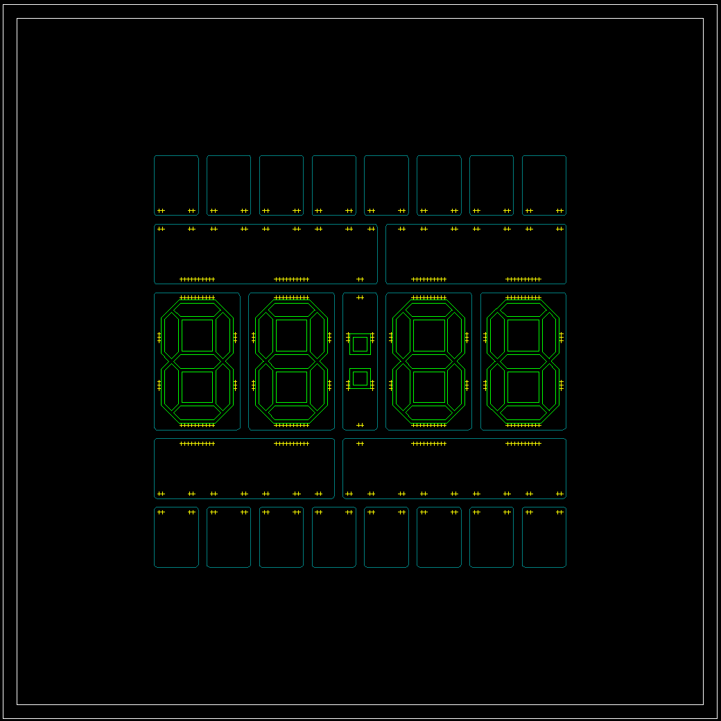
    The first step was designed with LibreCAD and OpenScad. The outer size requirement of 30x30cm and the gaps defined by the pinheaders as connectors gave me the required sizes for all PCB's.

    Schematic / Module Design

    Gemeral LayoutSince I planned to order a minimum of PCB designs (price!), I needed to develop even the modules modular, mostly via jumper pads that could be soldered together when needed. I also got rid of the Routing-PCBs and reduced the Signals to a minium.
    The FlipFlop modules should themselves be capable to build the beginning, the middle section and the end of a Johnson Counter. They also needed to provide access to the relay line, their inverted output signal or even the common clock signal via the configurable output pin. The schematic of the FlipFlop is schamelessly based on the original design - which was already a copy of another design already.

    The decoders needed some changes from the original design. I decided to place a "A&!B" Gate on each Decoder. One is needed for the reset (tens, hours) and the other three for monoflops to generate a short puls out of the rising flank of the most significant FlipFlop Output.

    Signals

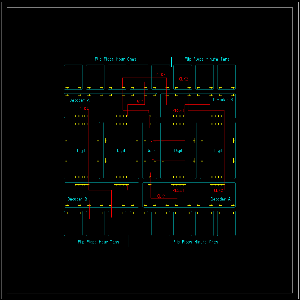
    Routing of signals between Modules

    All in all I could also reduce the signals that needed to be piped from top to bottom or from bottom to top down to four: Clk2 (Minute, tens), Clk4 (hours, tens), Reset and !QD from the "hours, ones" decoder (needed for reset condition). To achieve this, I just added a generic "pipe" signal to every digit. 

    The "dots"-module in the center got all the features that were necessary to set/reset the clock via an external micro controller. I chose the relays as "level shifters" to not break with the design concept. An nfet would have done the job as well, but what the heck. Two buttons got added as well to clock the minutes or hours up for the debugging. The dots themselves can be also controlled via the controller for debugging / connection info, but later more to that.

    Digits

    Seven Segment Digits were to way to go. But how? The required size can only be done custom and a multitude of leds like David did in his project is too power hungry for my taste. My first idea was to 3D-Print the frame of the segments and then to fill it with hot glue as a diffusor. The problem to that is simple: HEAT. The Frame will in the best case just bend and ruin the shape. So I had the idea to make a "mold" based on stacked PCBs to form the segments. The diffusor tests with the chosen LEDs and distances was promising. So lets wait and see if my mold works as good as it sounds.

    Project Status

    My PCB orders are dropping in one by one now and the Project logs will mainly be about the "putting stuff together" part. The "DecoderA" is already lying next to me - working. One Module down, 4 to go... 

View all 6 project logs

Enjoy this project?

Share

Discussions

Chris Arena wrote 12/26/2018 at 18:43 point

They are way to bright :)  ==> They are way too bright :)

  Are you sure? yes | no

SwiftyTheFox001 wrote 01/02/2019 at 07:26 point

thanks - will be fixed :)

  Are you sure? yes | no

Dave Gönner wrote 06/20/2018 at 10:18 point

You know what they say, imitation is the sincerest form of flattery. By putting the project on hackaday, I knew it could be copied. I like to see that you made your own design and even improved it. 


What's missing for the last PCB was indeed mostly time. I had some trouble fitting all the parts on the last board. But I finished the layout a few months ago. I moved away from Amsterdam, so it's not so easy to go to the Fablab and mill the final PCB there. I could have sent it off to a PCB manufacturer, but I want it to have the same look as the other PCBs. I have the files and parts I need, just need to go over there for a day and do it. 

Can I ask how you are powering your clock? Mine needs quite a lot of power because of the LEDs I used. So the power supply is almost a project in itself. How much power does yours consume?

  Are you sure? yes | no

SwiftyTheFox001 wrote 06/20/2018 at 09:46 point

Yes, the ticking is very satisfying. Mine is not at 100% as well, since it is a bit too bright but I'll tend to this later ... somewhen :)

What is missing for the last PCB? Or is it as most of the times the lack of time itself? I would love to see it finished!

Thanks again for the groundwork, your documentation made it easier to start mine. And also thanks for not being butt hurt for piggybacking your idea, I was at first not sure how you would take it.

  Are you sure? yes | no

Dave Gönner wrote 06/20/2018 at 09:21 point

Hi Swifty, Really nice project! Nice to see that you were inspired by my project and I really like the personal twist you gave to the design. My clock is indeed not finished yet, but the project is not abandoned. The design is complete, but I still have to fabricate the last missing PCB.
Anyway, great work, nice clean design and layout. I like reading about the improvements you made and hurdles you overcame along the way. Do you enjoy the ticking of the relays as much as I do? 

  Are you sure? yes | no

Similar Projects

Does this project spark your interest?

Become a member to follow this project and never miss any updates