Paul Kocyla
-
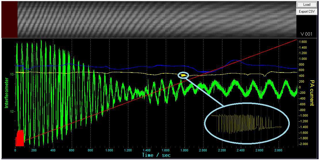
WTF happens here?
09/29/2015 at 19:27 • 7 commentsJust made a long time recording. I noticed this pattern here which also occurs in some short time recordings (in reduced resolution). I fixed the bug in the gfx, so it´s working now for long time recordings.
As you can see, the interference pattern is drifting over time, so the green curve becomes useless. I think I´ll need to code a tracker for the optical pattern.
But back to the phenomenon showed in the picture: What causes this oscillation? Is it a resonance phenomenon or some intermodulation due to the 5V-step-up converter? The real frequency is rippling relatively slow within a few MHz, maybe it´s the point it hits resonance while rippling around the center frq and so causing these peaks? I don´t know. Anyway it happens always around this frequency and only with the cavity connected, so it´s reproducible.
Do you have an idea?
(Data for the viewer is in the repository under Charts\AUX\20150929-03-...)
![]()
-
Software Released
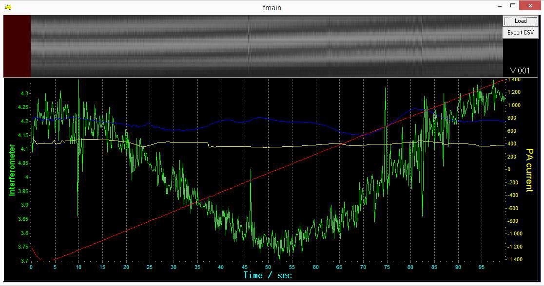
09/28/2015 at 11:13 • 0 commentsWe just released the software viewer for our EMdrive measurements.
It can also export CSV files. Download it from the repository under "ChartViewer". There´s no installation needed, just run the EXE.
We included a set of frequency sweeps (100s duration each). More charts will come.You can zoom and scroll within the chart. Pull a rectangle from topleft to bottomright to zoom, pull a rectangle from bottomright to topleft for reset view.
- Feature for the future: I will implement a tracker for the interferometer line at the top, this will make analysis a lot easier, but this will take some time, so I decided to release the software first.I will upload the longer sweeps (600s) after work which possibly show some force at about 24.6 GHz.
![]()
-
Sweeps
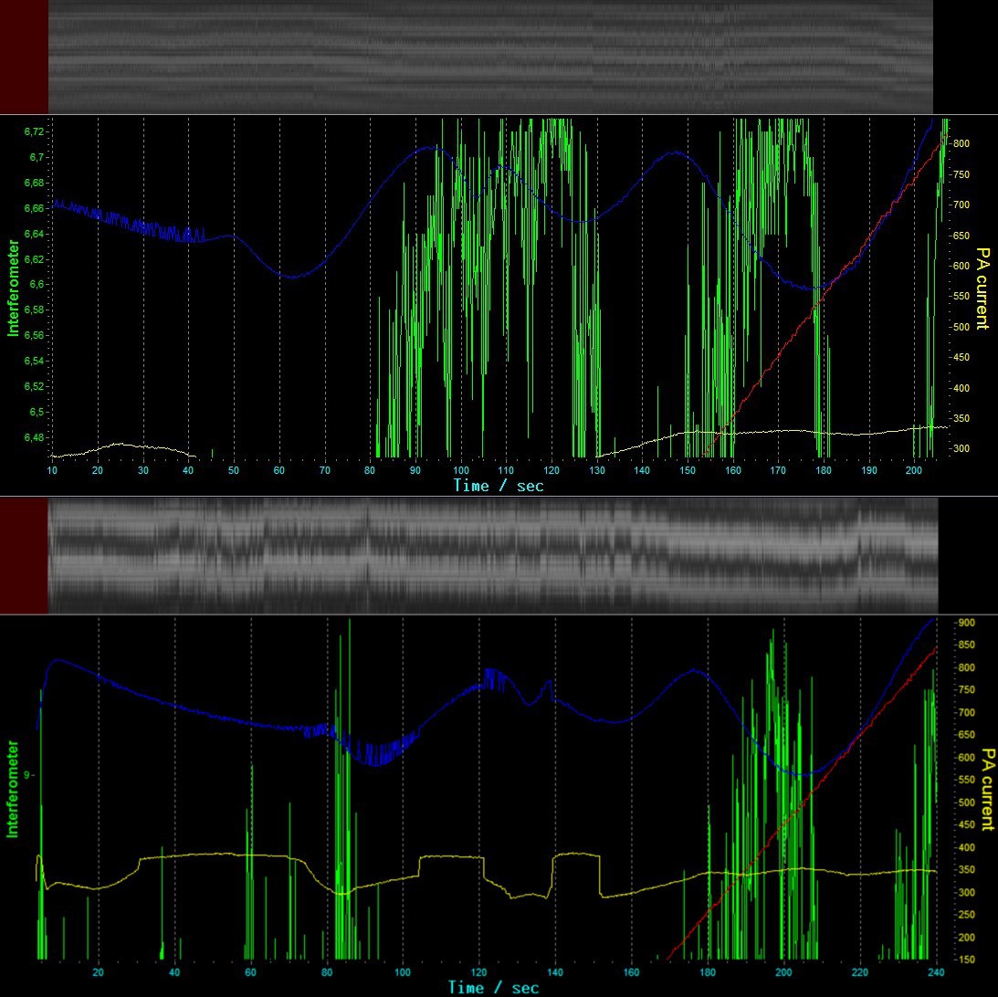
09/27/2015 at 21:01 • 1 commentDone some frequency sweeps between 22.0 GHz and 25.6 GHz and recorded the RX power, current and force in order to find some clues for the resonance frequency.
I did it first without antenna and then with an omnidirectional antenna and finally with the cavity (with tuning screw and with fixed endplates)
There is something happening around 24.6 GHz in the RX graph (600s sweep) which comes together with a force change (fixed endplate cavity) - but I need to check it in detail before I post some information based just on assumptions.
I wanted to release the software for viewing the data today, but it has still a bug in the display for recordings longer than 480 seconds, so I´ll fix this first before I release it.
Don´t worry, it won´t take long.
-
Explanations
09/25/2015 at 08:26 • 0 commentsTo avoid confusion, here are some explanations regarding the measuring procedure, the software and the orientation of the cavity:
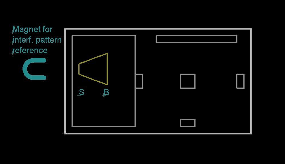
Here is the top view of the setup I will refer to from now on.
![]()
When I refer to the cavity orientation as "SB", it means that the "S"mall end is on the left and the "B"ig end on the right, "BS" is the other way around.
![]()
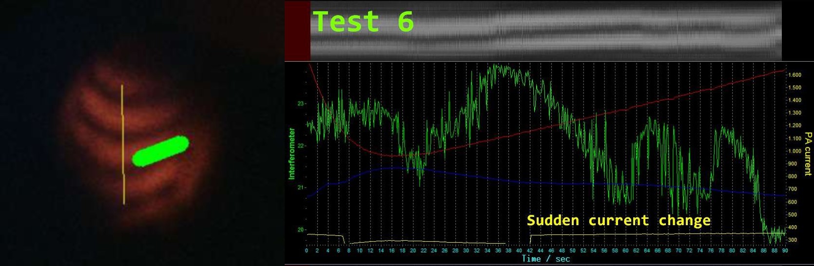
Here´s how the chart works:
- On the left side is the camera image of the interference pattern. The grey graph is a continous sampling of the yellow line in the interference image, so if the pattern moves up, the grey graph also moves up.
- The green graph is just the pixel brightness sum within the thick green line in the interference image. It will generate a more or less sinusoidal wave over time when the pattern is moving continously. However, it will not tell you the direction in which the interference patern is moving, but it might be helpful to make small changes more visible.
- After having adjusted the mirror to get a good interference pattern, it´s not clear in which direction the pattern will move in respect to the force.
I use a magnet to determine that. My reference will be "U" if the rings of the pattern go up and "D" if they go down while attracting the platform with the magnet. -
Got something
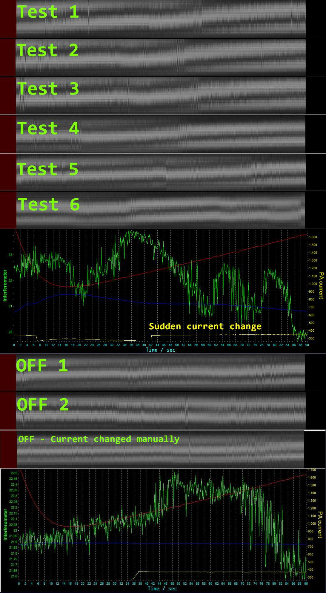
09/22/2015 at 21:03 • 36 comments![]()
Playing arround with the setup. It turns out that there is a change in displacement around 25 GHz. That´s the upper end of our RF source, but several tests showed a change here. It´s all the same in six continuous tests.
There is a sudden change in the PA current before the displacement change occurs. The interferometer change looks sometimes like cheaply cut in with a paint program, but it´s not, this are the original recordings. There are sometimes jumps in the interferometer lines. The chart update frequency is 5 Hz while the camera frequency is about 30 Hz, maybe that´s also the reason that these jumps look so sudden.
I inserted some tests with the transmitter turned off, as you can see the displacement doesn´t occur in that situation.
One possible parasitic force which could cause a displacement could be the current flow to the system. In the last test I switched the transmitter off, but manually adjusted the current to make it look like in the previous tests.
But it did not show the displacement. So it seems that the current flow does not produce parasitic forces.The interference pattern changes over time ( I assume it´s the temperature drop in the evening, so I need to adjust every few tests to get a reasonable pattern)
The experiment shows another implication of thrust - but we don´t shout it out yet ;)
We want first to know what you think about that. It´s the first test, so we don´t judge, we just play and watch.I´ll take some time to make the software ready for you to browse and export the data. Please give me some time.
-
Interferometer First Tests
09/22/2015 at 10:29 • 0 commentsStarted testing... or better preparing the test conditions.
It takes a while to adjust a good interference pattern. In the picture above there are too many rings, in the lower picture the pattern is much better.
I tested in the living room. The pattern was only useable after 11pm - with no movements in the room. Movements blur the pattern out, and it takes a few seconds to stabilize again.The PA current must be set correctly to deliver RF, I noticed that the RX power is probably most suitable to detect resonance conditions.
Blue graph: RX power
Grey: Scanlines of the interferometer ringsRed: Frequency: 24000 MHz plus yellow scale
Green: Pixel sum between interference rings (results in a sine wave when multiple bright/dark regions are crossed) It helps to see small changes less than 1/2 wavelength.
I believe to see changes correlated with the frequency around 24500 MHz, as they seem to occur with bending of the interference pattern in several tests. But maybe I only see ghosts - that´s just an assumption.
I´ll take more tests today and will try to further stabilize the interference pattern before progressing with regular test runs.
I will also try several positions of the tuning screw - so it´s still a lot work to do.
I´ll be also very careful with shouting out positive results, unless I am convinced that there actually might be thrust.It will be exciting, let´s see what happens.
About test data:I will provide the software for free download, so you can easily browse the chart with realtime zoom function, including the 30fps scanlines of the interferometer rings.
There will be also an export function for the data into a CSV text format.![]()
-
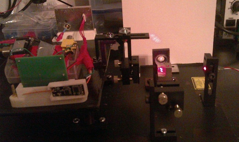
Interferometer Setup Ready
09/21/2015 at 07:45 • 8 commentsThe interferometer setup is ready for testing the Baby EMdrive.
Hardware and Software are running. We are excited to make some measurements.
![]()
-
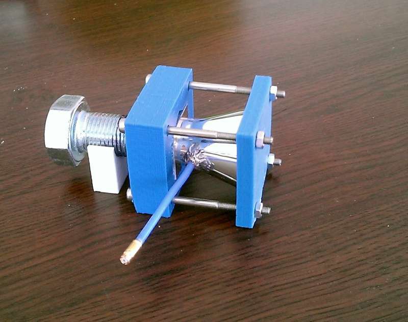
Silver Cavity Assembly
09/15/2015 at 16:09 • 1 commentHere it is, the cavity with tuning screw. Soldering the antenna shield to the cavity was no problem at all after having brushed the place.
![]()
-
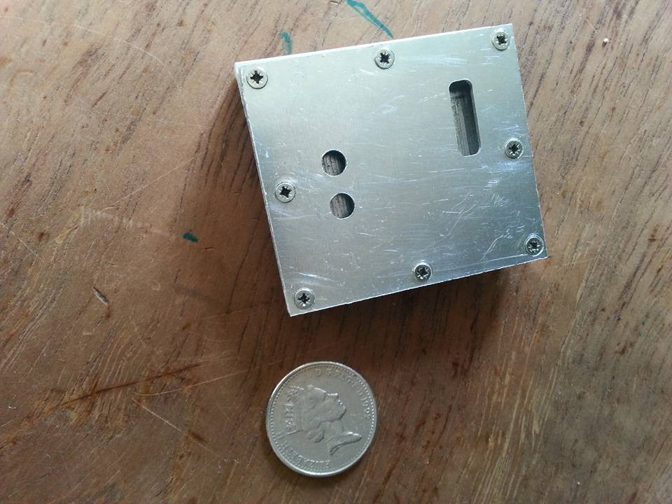
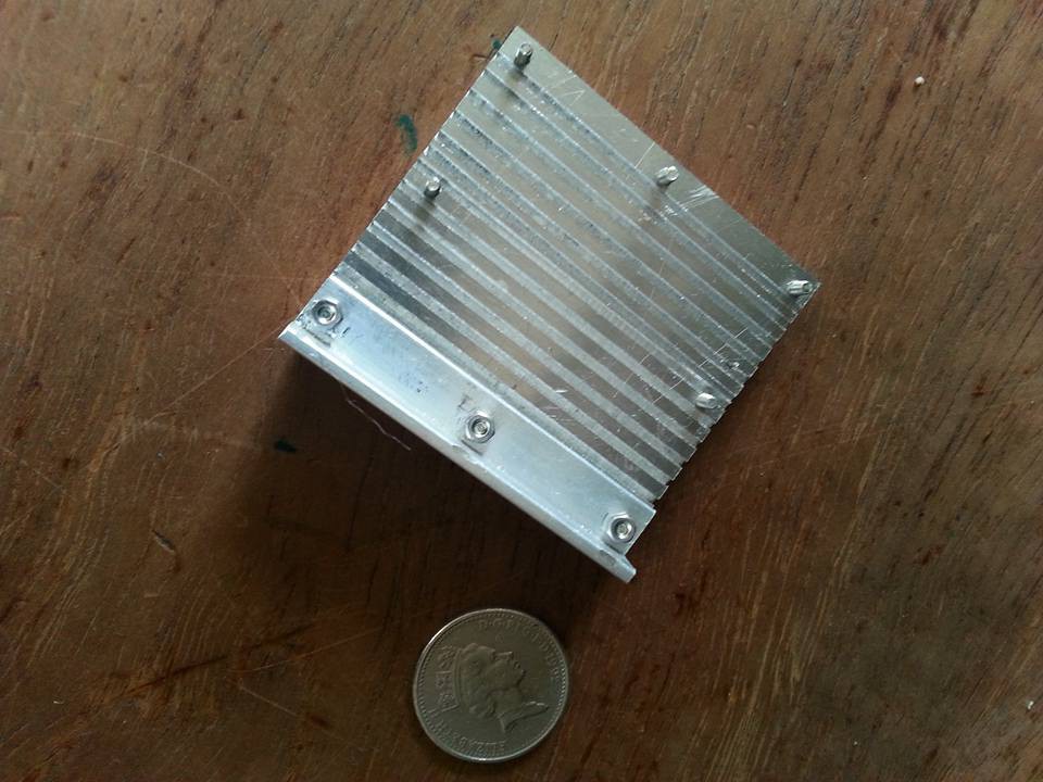
RF Housing
09/09/2015 at 18:47 • 2 commentsJo is milling the housing/radiator for our new RF source.
We´ll have a heat dissipation of about 2 Watt, and we need a proper shielding, so a good housing is mandatory. You can burn your fingers on the ICs at nominal parameters (500mW output @ 24 GHz)--
Update: Jo finished the housing/heatsink
![]()
![]()
![]()
-
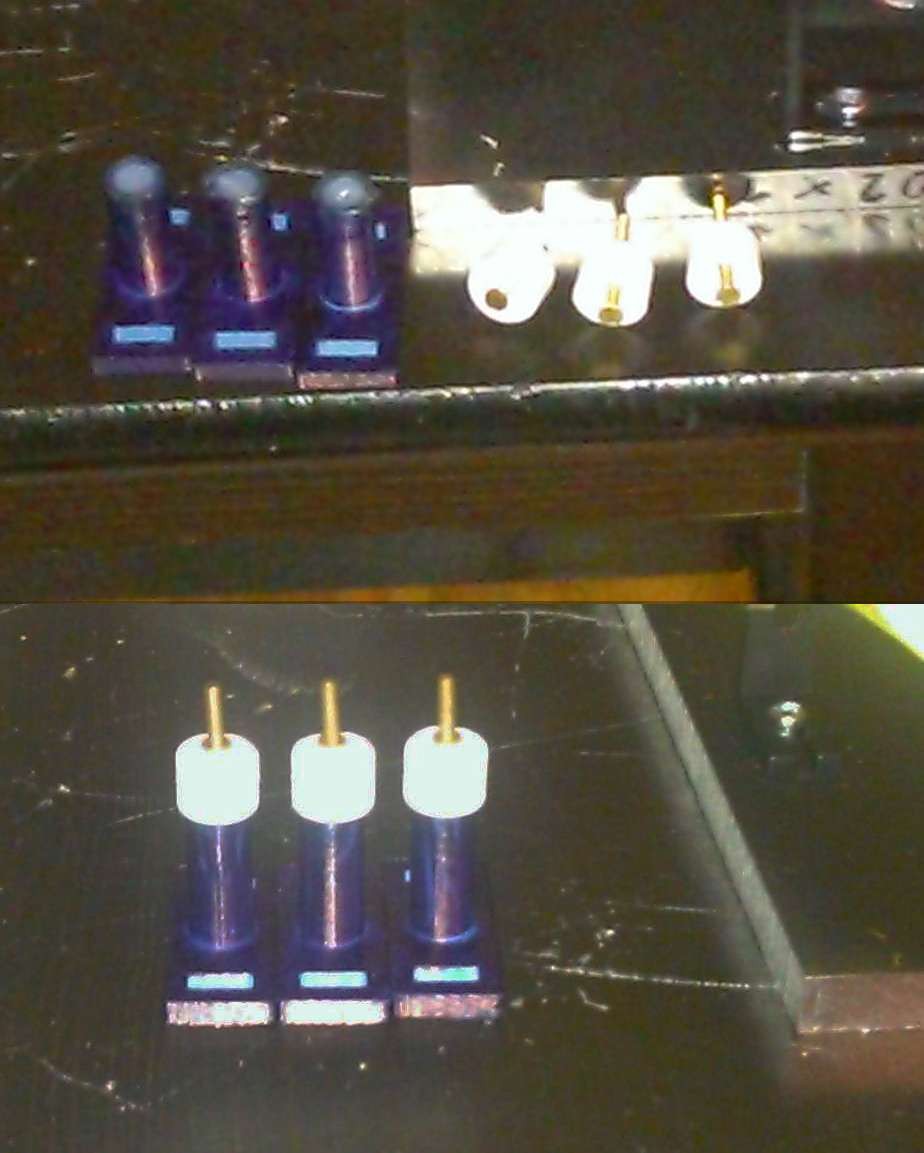
Elastic suspension
09/08/2015 at 20:33 • 2 commentsTrying to make an elastic suspension for the EMdrive, so it can be displaced enough to be measured by the laser interferometer - in case a force occurs.
I filled three cylinders with silicone and inserted a screw into each of them. I hope this will be elastic enough. The caps on top are just for holding the screws in a vertical position until the silicone gets harder, they will be removed later.![]()