Redtree Robotics
-
Complete Rover Build
07/29/2015 at 13:07 • 0 commentsAssemble the Rover Frame
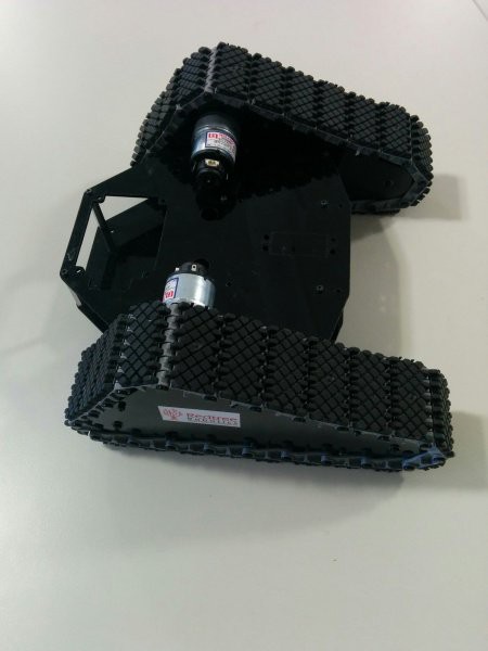
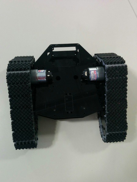
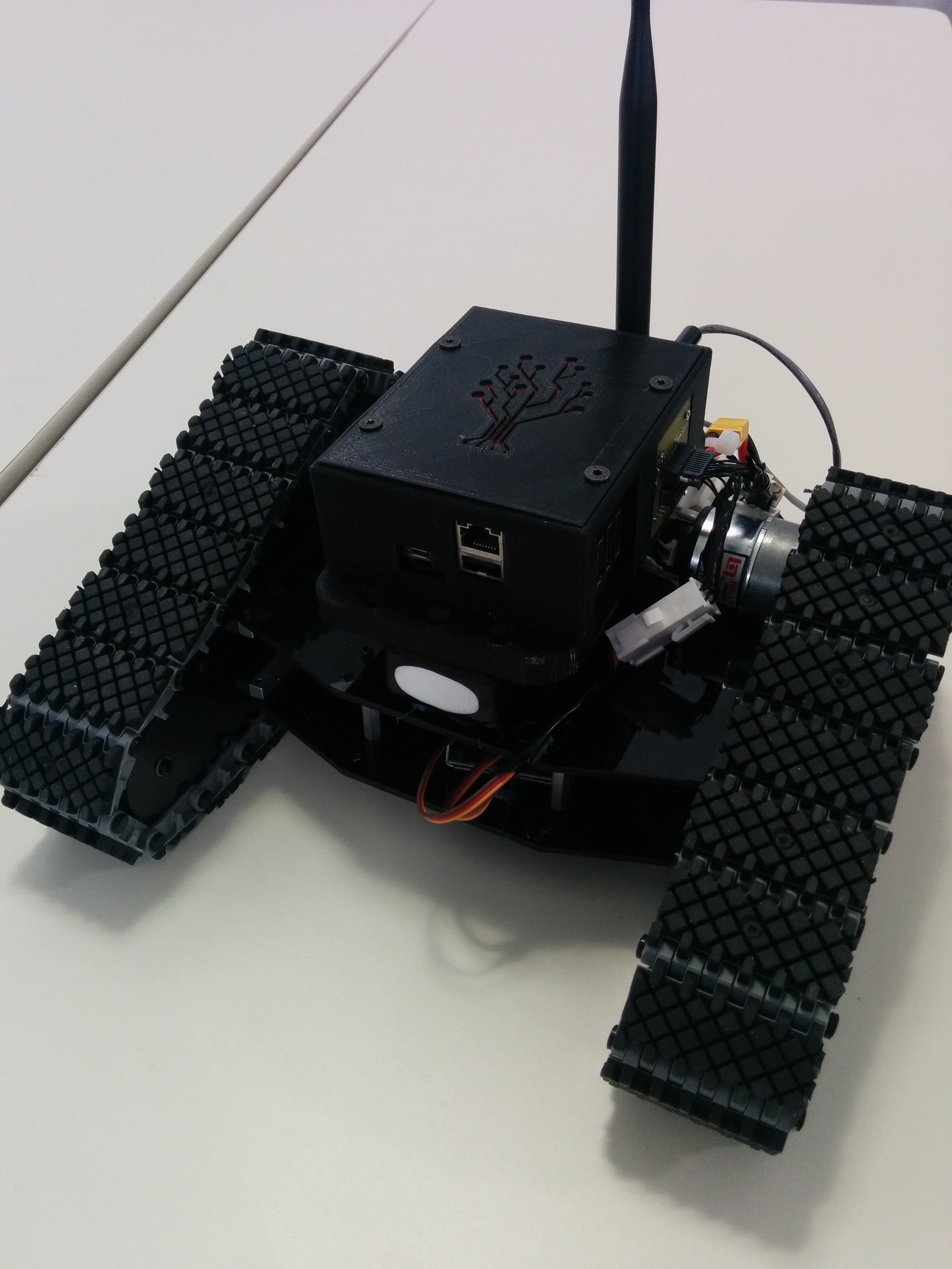
We used a rover kit from Robotshop: http://www.robotshop.com/ca/en/lynxmotion-tri-track-chassis-kit.html. Assemble it according to their instructions to build the frame and attach the motors. You can also use other kits, but you may need to make adjustments to the current outputted to the motors if you use something else. It should look something like this when you are done.
![]()
![]()
Attach the motor controller
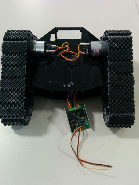
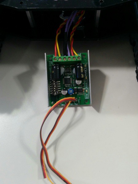
We used a motor driver from Robotshop: http://www.robotshop.com/ca/en/sabertooth-dual-regenerative-motor-driver.html - wire up the motors to each channel, wire up power and ground from the battery and attach the wires to the motors. It should look like this when you are done:
![]()
![]()
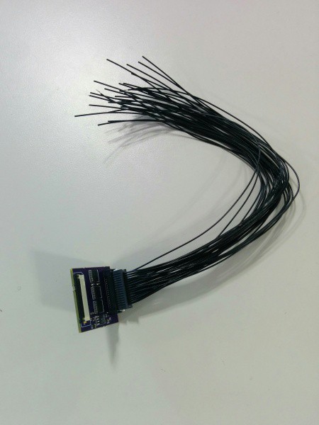
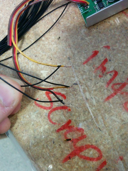
Insert the Redtree I/O card into the Redtree Hydra
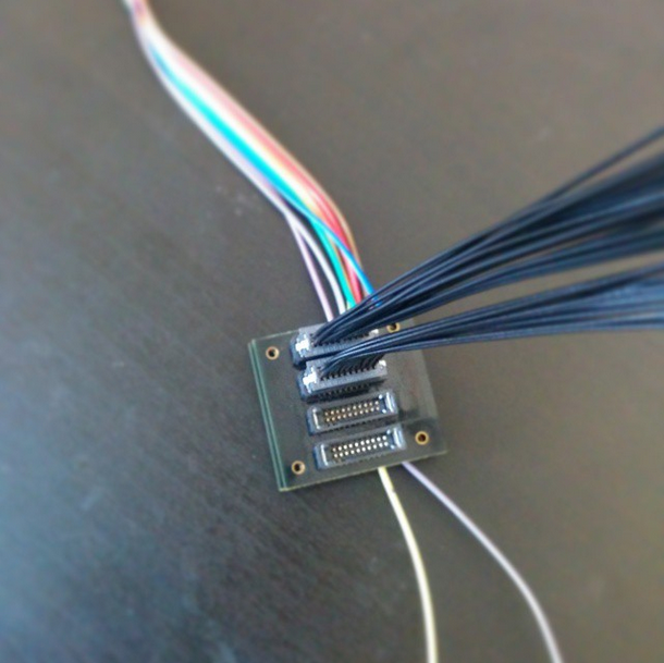
Insert the ribbon cable from the Redtree Hydra into the I/O card. Attach the I/O card wiring harness to the card and then wire the wires into the motor driver. You can configure which wires / pins control the signals with the FPGA configuration tool. We attach the appropriate wires from the configuration tool to the signal wires on the motor driver. Our I/O card also provides power and ground so we attach these to the motor driver as well. The yellow wires are the signal wires and the black is the ground wire on the motor controller.![]()
![]()
![]()
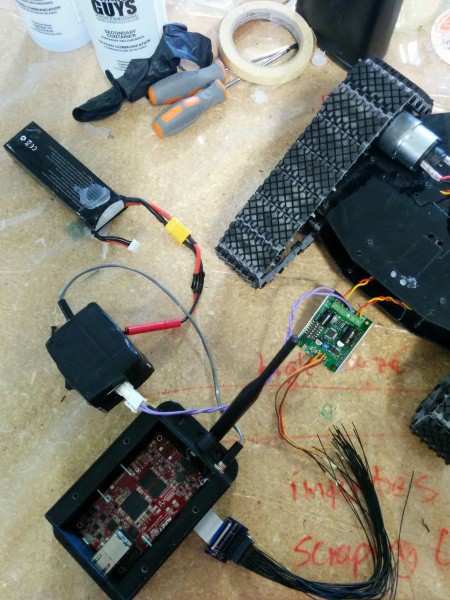
Attach Voltage Regulator
The Voltage regulator converts the battery from around 11 volts to 5 volts which is what the Redtree Hydra requires. We also added a switch here so we can turn the whole robot on and off. We have this wrapped in this black styrofoam / electrical tape to give it a bit of a cleaner look.![]()
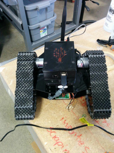
Attach Xbox Receiver and Cleanup
The last hardware step is attaching the Xbox receiver: http://www.amazon.ca/HDE-Wireless-compatible-Controllers-Platforms/dp/B0096PLB9O since we are using an Xbox 360 controller to drive the robot around, and cleaning everything up. We basically just cable tie the wires and hot glue everything down so that it stays in place.![]()
Programming the FPGA
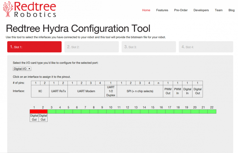
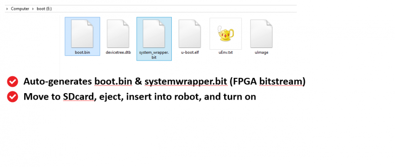
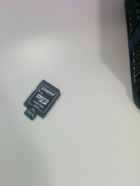
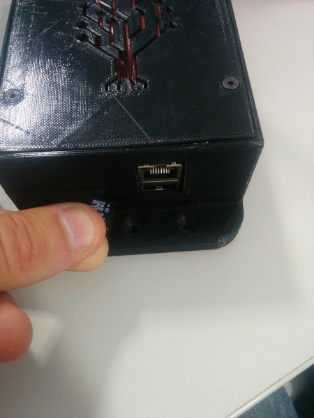
For more detailed information, see FPGA configuration tool. In this step, we use the web tool which will be available at http://www.redtreerobotics.com/fpga to program the fpga. This tells the Hydra what pins on the I/O card are attached to the motor controllers. In this case, we are using two digital I/O, so we click "digital out" twice to add this to the pinout, and click finish.![]() When you click finish, the tool will automatically generate the files to program the FPGA when the Redtree Hydra is booted. Take the SDcard out of the Redtree Hydra and insert it into your computer. The two files 'boot.bin' and 'system_wrapper.bit' should be moved to the SDcard. The SDcard can then be ejected and re-inserted into the Redtree Hydra.
When you click finish, the tool will automatically generate the files to program the FPGA when the Redtree Hydra is booted. Take the SDcard out of the Redtree Hydra and insert it into your computer. The two files 'boot.bin' and 'system_wrapper.bit' should be moved to the SDcard. The SDcard can then be ejected and re-inserted into the Redtree Hydra. ![]()
![]()
![]()
Programming the Robot
Next, turn on the robot, connect to its Wi-Fi network (default is rtr), and ssh to the robot. Default IP is 192.168.8.1. The username and password is "redtree" and "robotics".
Check out the "hello rover" example from the Redtree Apps repository:
svn co http://www.redtreerobotics.com/svn/redtree-apps/trunk/ redtree-apps
cd redtree-apps/hello_rover
or if you prefer git:
git clone https://github.com/redtreerobotics/redtree-apps.git
cd redtree-apps/hello_rover
You'll notice a makefile, a header file, and a .cpp file file. The Makefile has been setup to download the Redtree libraries automatically. It is also set up to automatically compile together any .cpp that exist within the folder, so feel free to add your own .cpp files as your projects become more complicated.
Compared with the previous two examples, we have spit this one into a header and source files. This shows a slightly different way to organize the files instead of doing everything in the source file. Let's start with the header file. There are a few key things here.
First is including the "rt_input_user" file. This brings in all the code for handling user input from Joysticks, Xbox controllers etc.
Second is "XBOX_Joystick Joystick{"Joystick"};" - this defines the xbox controller module within our rover module. It has it's own initialization, configuration etc. that occurs without the programmer having to worry about it.
The last thing is the line that defines the control routine as an m_worker. This means it is a real-time task that we can run on specific intervals. There are more details on this in the source file.
#ifndef HELLO_ROVER_H
#define HELLO_ROVER_H

/*
 * Basic code that makes a driveable rover with
 * a controller
 *
 * Jason Ernst, 2015
 * Redtree Robotics
 */

#include <rtr.h>
#include <rt_input_user.h>

void configure(void) {}
void initialize(void) {}
void setup(void) {}
void start(void) {}

class redtree_rover : public m_device
{
	public:
		using m_device::m_device;

		XBOX_Joystick Joystick{"Joystick"};
		m_worker<void, void> Control_Routine{this, "Control_Routine", std::bind(&redtree_rover::control, this)};

		void configure(void);
		void start(void);
		void control(void);
};

#endif
Let's look in more detail at what is inside the hello_rover.cpp file. This file contains the code that will run on the robot. You can open this with your favourite editor and work on the code in here. Again there are a few key things to notice. First is that the Control Routine does not start running until the Joystick has started. When it does start running, it runs every 1/10 of a second. When our rover module starts, the first thing it does it start the Joystick module. Lastly, the Control Routine checks to see if the FPGA is present and then writes the Joystick values to it (after scaling and deadbanding to ensure it is in a correct range). Note: if this code is run on a computer instead of the robot it will just output the message "NO FPGA FOUND" instead of actually writing to the motors.
One final thing to note is the addresses to write to - these addresses are generated by the FGPA programming tool, but in a future release we will automate this part so that instead of addresses a textual define is used instead. For instance MOTOR_1 and MOTOR_2 (which the developer would specify in the FPGA tool).
When you open the file you should see something like this:
#include "hello_rover.h"
#include <iostream>

/*
 * Basic code that makes a driveable rover with
 * a controller
 *
 * Jason Ernst, 2015
 * Redtree Robotics
 */

redtree_rover rover{"rover"};

void redtree_rover::configure(void)
{
	Control_Routine.run_every_when(100000, Joystick.Started);
}

void redtree_rover::start(void)
{
	Joystick.StartCommand();
}

void redtree_rover::control(void)
{
	if(m_fpga::isFound())
	{
		m_fpga::write(0xC00,1500 + (int32_t)scale_deadband(0.01, 3200, Joystick.Left_Joystick_Y()));
		m_fpga::write(0x800, 1500 + (int32_t)scale_deadband(0.01, 3200, -1*Joystick.Right_Joystick_Y()));
	}
	else
		std::cout << "NO FPGA FOUND" << std::endl;
}
This file is a bit more complicated than the simple "hello robot" example from earlier, but still pretty simple. Our toolchain and libraries take care of all of the rest of the work for you. To compile, just type make in the terminal where you checked out the code with subversion.
makeRestart and Test the Robot
For now we require the robot is completely reset when it is reprogrammed (otherwise we can't guarantee the state of the system when new user code is loaded. So turn it off and turn it on again and it will automatically load the code you just compiled. It will take up to 30 seconds but once everything loads everything the robot should be drivable with the controller.
-
Redtree Hydra: Software Model
06/05/2015 at 10:59 • 0 commentsIn the Redtree Hydra system, everything is an m_module. This could be algorithms, entire robots, sensors, motors or anything else which might make up the "robot". This class defines what makes up the component (data types, other m_modules, m_devices etc).
A special type of m_module is an m_device. This is similar to an m_module except that it has defined behaviour states for handling failures. This is useful for things like motors or sensors. You might wish to attempt to land a flying device on a sensor failure to try to avoid a crash.
Repeating executable functions are given the type m_worker in the Redtree Hydra system. Functions which should run once are given the type m_job.
m_module
An m_module has several important functions which define the behaviour when the module loads.
configure()The configure() function is called for every single tag, device, and module in reverse creation order.
The configure function lets the user set data dependicies for m_extern tags and low level settings like queue sizes based on low level settings. Which means this step is to setup the device/module/etc. into a state that it can then be initialized.
initialize()The initialize function is used to apply the configuration that was created in the previous step. This steps are separated because parent modules and devices will likely change the configuration of child tags/devices, and modules. (i.e. A the CANOpen protocol module will change the baud rate tag of the CANBus Peripheral, or a Motor will configure the gains of its Control System Module)
setup()The setup function is provides an intermediate step between initialize and the device/module/or tag starting its runtime behaviour. Sometimes this is necessary depending on the complexity of module/device or tag.
start()Finally, the start method is called. The start function of any tag, module, or device must bring that component to its normal runtime state, and execute "Started = true;" once the unit is functional and runtime capable.
m_device
An m_device inherits all of the previous functions specified from the m_module above. In addition, there are some extra functions which are used to handle failure cases.
m_worker
In order for a module or device to run executable functions periodically or continually, the code must be wrapped as an m_worker. This allows the code to function with tags and take advantage of the real-time and seamless networking features of the Redtree Hydra system.
Here is an example of a globally available m_worker:
m_worker<void, void> my_task{"my_task",[&](){
	cout << "Executing my task function" << endl;

}};
And here is an example of an m_worker defined within a class:
class myclass : public m_device
{
	public:
		using m_device::m_device;
		void configure(void){}
		void initialize(void);
		void setup(void){}
		void start(void){Started = true;};

	private:
		int sockfd;
		struct addrinfo *servinfo;
		void send(void);
		m_worker<void, void> myclass{this, "myclass", std::bind(&myclass::my_task, this)};
};
myclass my_instance{"my_instance"};

void my_instance::my_task(void)
{
	cout << "Executing my task function within a class" << endl;
}
Periodic User Functions
User functions within an m_module or m_device can be run every x microseconds.
For instance, if you have an m_worker called my_task, you can run it every 500ms as follows:
my_task.run_every(500000)
Continual User Functions
You can also have a function run continually (it does not wake up on enforced time schedules - it is essentially a non-realtime task)
This is the type of function you would run a busy loop inside of if, for some reason you needed one. Note - in either of these cases - both of the functions never return - they will just be called over and over again.
my_task.run_when(Started);
Right now, it is only possible to run continual functions on a trigger (for example when the module has started) - but in the future we plan to allow functions to just "run" as soon as possible by removing the constraint. See triggered functions below.Triggered User Functions
Continual or periodic functions can run on a trigger or for the case of a periodic function, just run every x microseconds. Here are a couple of examples of triggered functions:
my_task.run_when(Started); //continual, triggered
my_task2.run_every_when(250000, Started); //periodic, triggered
In both of these cases, the functions won't run unless Started == true.This information can also be found on the Redtree Wiki
-
The Redtree Hydra Software
05/22/2015 at 14:32 • 0 commentsThe last few posts were pretty much all about progress so far related to hardware. This update will be focused on software. What makes the Redtree Hydra run, how do you program it and what is the current state.
FPGA Configuration / Programming:
Since the Hydra runs an FGPA - and this is how all of the peripherals are connected (enabling really flexible I/O assignments and near plug-and-play robotics) - we have a configuration tool being completed where you specify with a graphical interface exactly what you are connecting to the robot. For instance, you might some UARTs, and some analog I/O for your particular robot configuration. You might want to come back later and add I2C as well - that is all easy and possible. Our toolchain will then configure the FPGA bitstream for you so you don't have to program in VHDL or Verilog.
Real-time Linux:
Next for the operating system. One of the key limitations of many of the existing platforms people use for robotics is that they aren't real-time. In some cases - they are "deep-embedded" and don't run Linux so they are totally dependent on the libraries created for the platform. We have a customized Linux 3.14-RT kernel. This means you get the benefits of real-time along with the flexibility of full compatibility with anything that runs on Linux. Furthermore, we run Debian, so you can also take advantage of anything in the Debian armhf repositories.
Library Compatibilities:
We know that people who build robots like to use whatever tools are available, and we aren't interested in re-inventing good things ourselves. Our systems are compatible right out of the box with ROS, OpenCV and other popular robotics tools. Further down the line we can see compatibility with Matlab / Labview as well.
Redtree Middleware:
In order to make it easy to access data from the sensors, motors and components connected to the robot, we also provide a library of function calls that work with the FPGA side of things. In addition, this library also provides a framework for easily programming real-time tasks, tasks that fire on data changes and lots of other cool features we'll post about in future updates. Finally, because the Redtree Hydra comes with built-in Wi-Fi, Bluetooth, 4G/LTE and Zigbee - part of the middleware manages all of these networks for you. The software will automatically form mesh networks between groups of Hydras in range of each other. If one network goes down (eg: Wi-Fi) the Hydra will automatically continue to use another option (eg: 4G/LTE). The same libary also provides the ability to send any data point (ie: variable) into the cloud with a single function call.
Wireless Configuration:
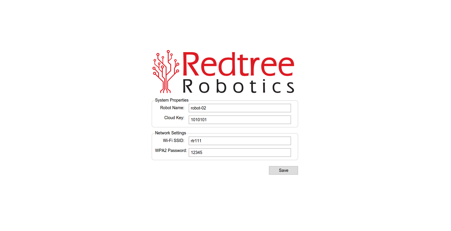
On first boot of a Redtree Hydra, the system creates it's own Wi-Fi access point which the programmer can connect to with a computer. The programmer can then visit a webpage and configure it, similar to how setting up a DD-wrt router works. This is an early version that just lets you configure the Wi-Fi SSID, name the robot (this is important if you want to write code in one robot that depends on a very specific second robot), and some of the cloud connectivity.
![]()
Cloud Connectivity:
On the cloud side, anything from the robot can be visualized in near real-time (all the data is dumped to a MySQL DB so you can use the cloud infrastructure we are building or use your own - you own all of your own robot data). Here's a short video that shows a little bit about what this means:
There will be more details to follow including some sample code in the coming days, but hopefully some of this has piqued people's interest.
-
Prototype 3: Redtree Hydra Drone (WIP)
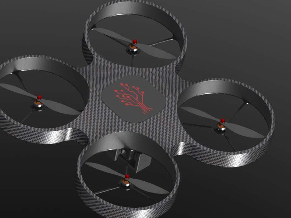
05/21/2015 at 15:39 • 0 commentsThis prototype system is a bit of a work in progress. To show that the Hydra system isn't just made for rovers, we wanted to also put it on some drones. We are working on a bolt-on kit for getting it integrated into the typical commercial drones such as 3DR and DJI, but in the meantime, we're also building one ourselves.
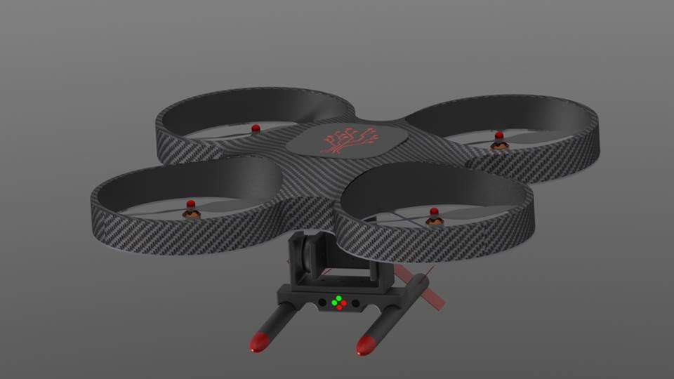
Here's a few of the original renders of it:
![]()
![]()
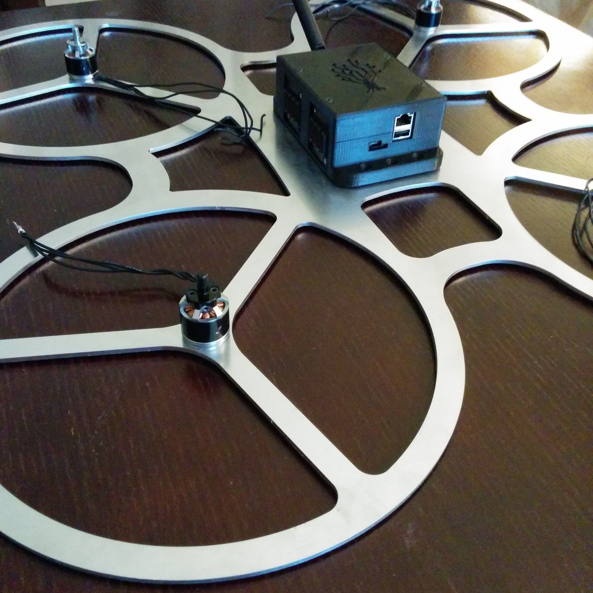
And here's what we have so far. We made a laser cut frame to put everything on (everyone keeps telling us it looks to heavy to fly, but we'll see - it feels pretty light, and according to Tom's calculations is something like 800grams, and each motor provides 1000grams of thrust, so should be okay (Our computer is pretty light as well).
![]()
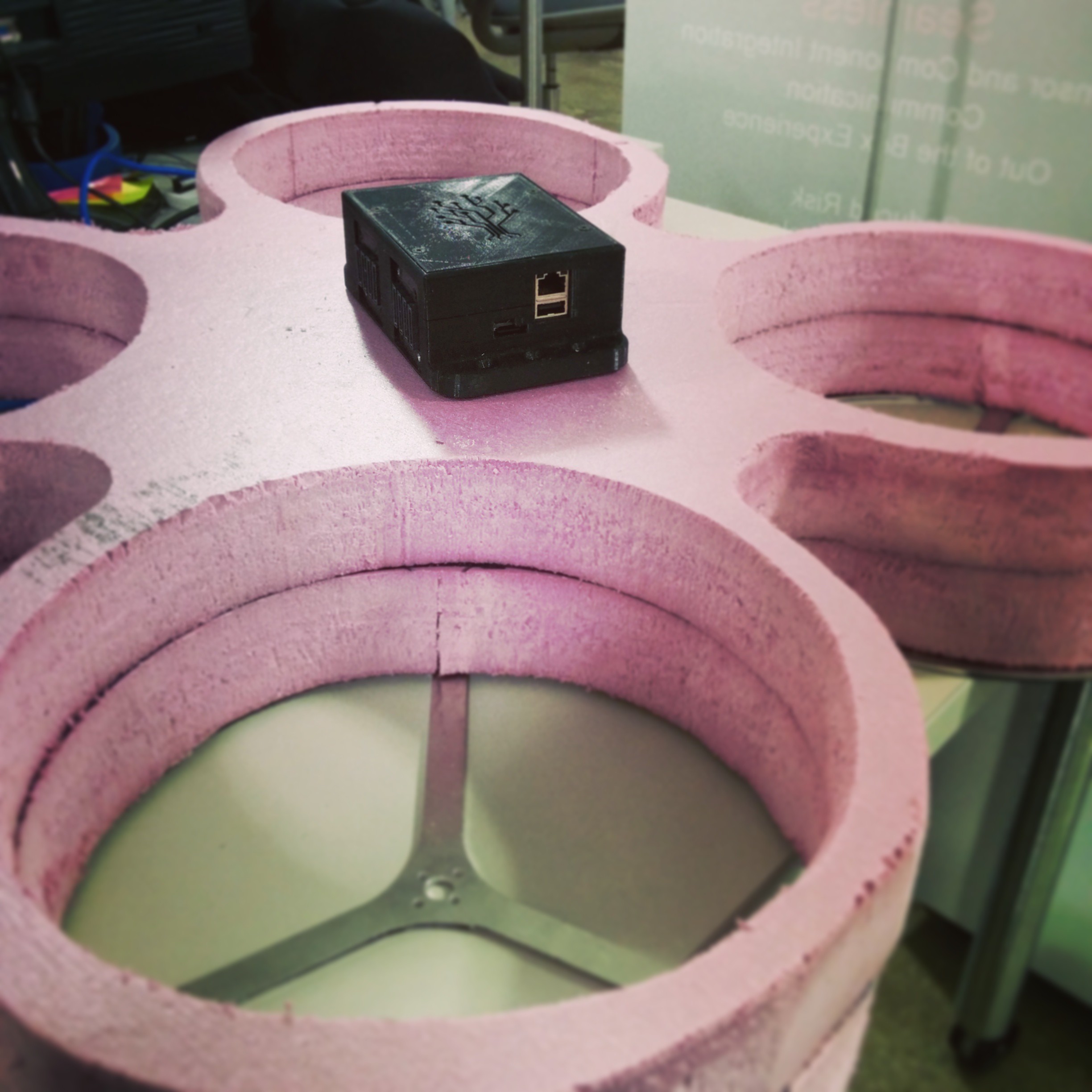
And a foam "body" to go over top of it:
![]()
And here's a quick video of the Hydra spinning up the props:
We just need to find some time to try to fly it and work on the stabilization now. More to come...
-
Prototype System: ODG J5
05/20/2015 at 13:03 • 0 commentsAfter getting a couple of the Redtree Rover prototypes working, we set out to put our system on more of a "serious" robot. We connected with a local company called Ontario Drive Gear, that makes awesome all-terrain vehicles (most of them people drive and have up to eight wheels and can float). They also have a robot version - called the J5, which is used by the military. We set out to replace the computer that was currently used in it and see how quickly we could do it.
Inside, it ships with either no computer or a single board intel-based computer (basically a laptop without the case). While this type of setup has lots of processing power, the ability to add video cards to extra vision processing etc. it lacks the ability to easily add sensors and components to the system. The current method is usually just adding another USB --> <insert x standard> + a bunch of software to make things work.
With the Redtree Hydra, since it is flexible and supports most standard interfaces its possible to connected directly to the CANbus for example and control the motors on the machine directly. More importantly, the same computer can also be used to connect LIDAR, IMUs, Manipulators and all sorts of other cool things directly and without a ton of extra adapters. Furthermore, the data from all these things is easily sharable with other robots (if you are building a swarm for example) or can be monitored live through our web interface.
Here's a few pictures and video's of our progress.
![]()
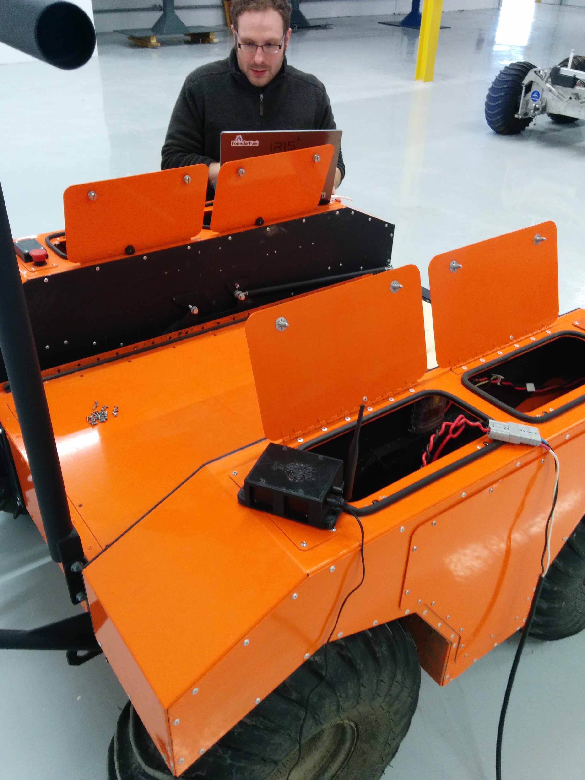
Tom doing some CANbus programming on the Redtree Hydra so we can control the motors.
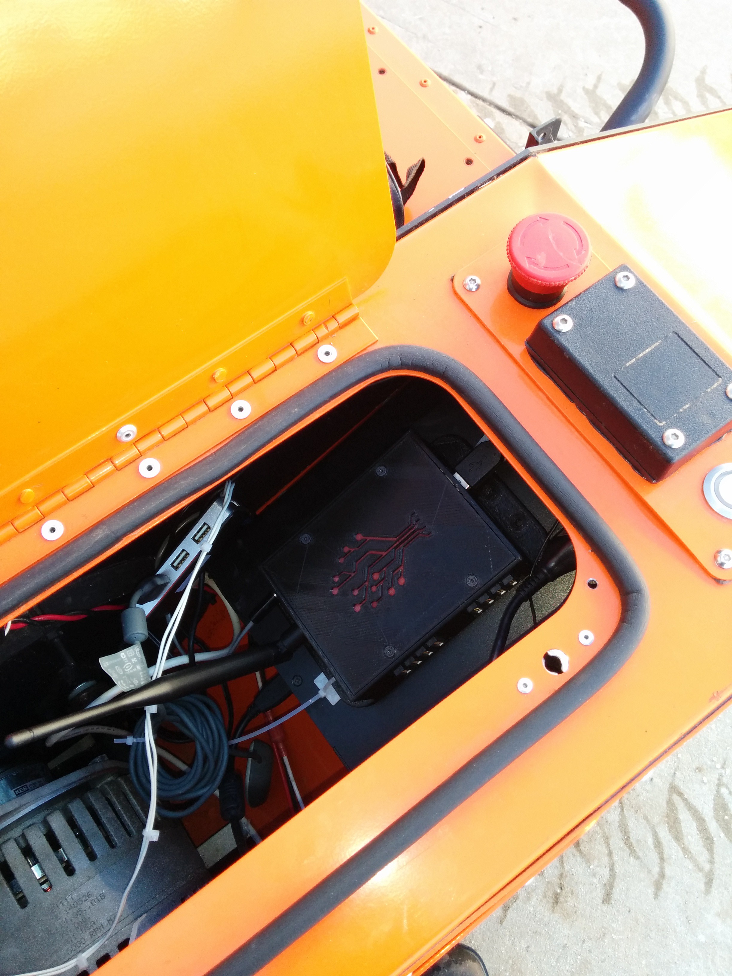
![]()
Redtree Hydra inside the ODG J5 - also has a smaller footprint than most computers that control these types of robots (it is sitting on top of the existing computer it is replacing. Note: we steer the robot around with an Xbox 360 controller, but it is also possible to use a longer range controller like a Futaba, which is more common with these types of machines.
This video is our first test of the system running the robot! Overall, it took us about a day and a half to get it to work with this robot - and most of it was programming and debugging interoperability with the CANbus for the motor controllers - in the future - this will all be available for anyone using the Redtree Hydra so that type of code won't need to be re-invented again. It will be packaged as part of our API libraries.
-
Prototype System - Redtree Rover
05/19/2015 at 18:51 • 0 commentsThe first prototype system we built around the Redtree Hydra was a rover. We got a small rover online and added the Redtree Hydra to it, along with some QEIs to measure the wheelspeed, and xbox controller receiver to control it (although you can actually control it from a computer over the network as well) and some power electronics to power it from a drone battery. (I'll detail this more in a full build instruction type of post later for anyone interested in trying to build one of these themselves).
Here's a few pictures and videos of the first versions of the rover:
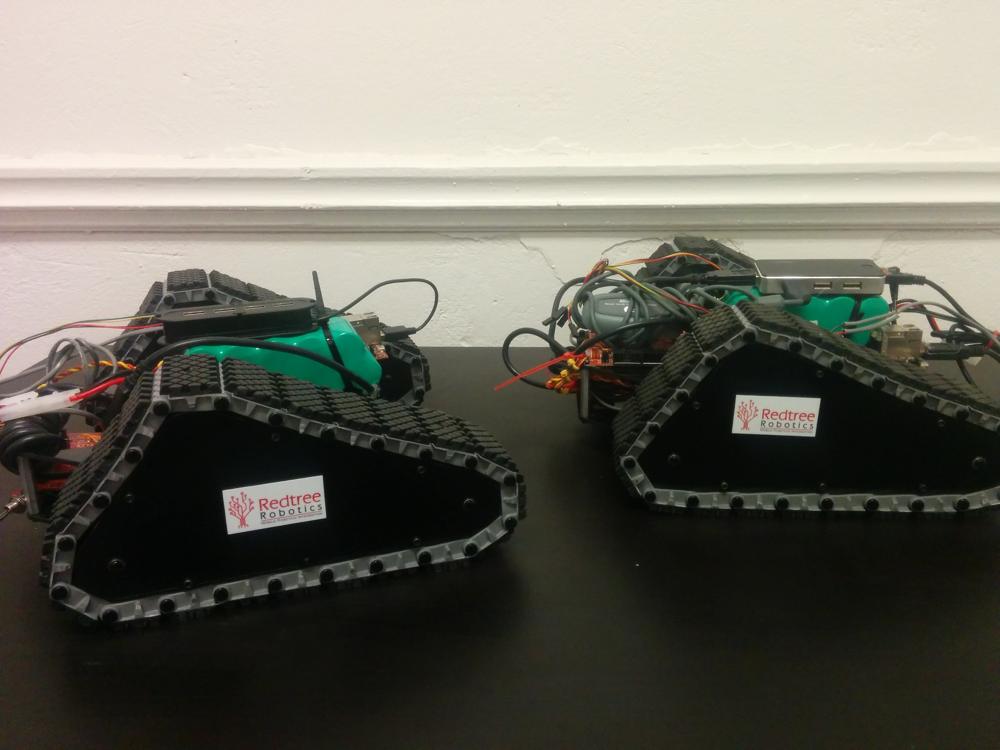
![]()
(version 1: running on some really early prototype hardware - not all of our boards are being used yet - no I/O cards - just some hacked together stuff mostly to test the software out)
![]()
Our most recent version using the prototype I/O card and our full hardware as well the software. In addition to providing the motor control for the robot, it is also possible to add a variety of other sensors, cameras - even a full robot arm and control it all with this single computer. In other projects this is often done by adding another micro controller or processor every time a new component is added to system. By keeping everything connected to one unit, it becomes more maintainable and easier to work with.
-
The Hardware Evolution of the Redtree Hydra
05/15/2015 at 12:50 • 0 commentsToday's log will bring you up to speed with the progress we have made up to until now from a hardware point of view (software side coming soon).
First, way back in 2011 when we were trying to figure out what was possible, we started to play around with a GumStix. It was attractive because we wanted built in wireless and a decent processor at the time (also fairly low power).
We quickly found out that to make the "plug-and-play" type of robotics we wanted, we would need a Field Programmable Gate Array (FPGA). This is sort of a software defined processor. It's useful in this project so that we can reconfigure the circuitry and connect hardware using different interfaces (I2C, Canbus, UART etc.) without a ton of external circuitry.
So after getting some of the code running on the Gumstix and convincing ourselves that this was worth pursuing we started on selecting a new platform that had an FPGA and some of the other features we wanted.
We ended up deciding on the MicroZed because it had a dual core ARM-a9 and an FPGA built-in. There also seemed to be a growing open-source community around the product, which was perfect since we also want to open source as much of our product as possible as well.
While it does not come with built-in wireless, we found a module called the TI Wlink8 which has WI-Fi and Bluetooth and had lots of documentation on getting in running with the microzed (and AVNET has been really helpful in working closely with us to get it up with our own board we developed).
After one hardware iteration, we had a fairly large footprint and the Microzed sitting on top of the board. In our next revision, we shrunk a little bit while sorting out some of the previous problems. The I/O connectors are now moved off onto external cards that would plug into the side of a case.
In our final production model, we are actually eliminating the Microzed completely and just utilizing the Zync 7010 processor and RAM (not sure how much yet, but likely more than 1GB).
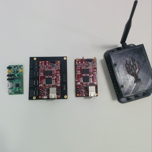
![]()
The above picture shows the evolution of the Redtree Hydra from around 2011 when it was mostly software running on a Gumstix to today where we are on revision 3 of our hardware and on the way to a manufactured production model sometime towards the end of this summer. The first version of our hardware was produced in April 2014, the smaller version in October 2014, the case in December 2014. We produced 15 of the most recent prototype which are being loaned out to early adopters at Universities and companies around North America. Our "manufacturing-ready" final version is expected in mid-to-late summer of 2015.
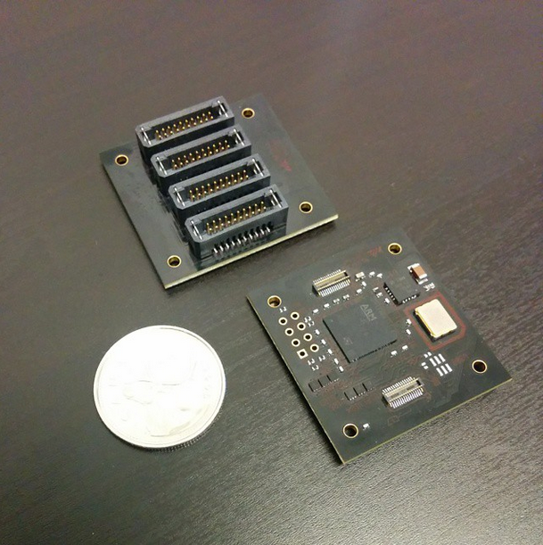
![]()
Above is a picture of the I/O boards on the side of the case that let you connect sensors, motors and other components to the Redtree Hydra. Eventually we think we can get the entire system down to this size or smaller so that people can incorporate the entire "chipset" into their own designs for mass production while retaining all of the features of the Redtree Hydra.
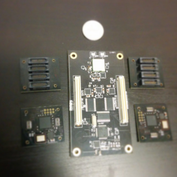
![]()
This is the entire system - or what's in the box. Our final production model will eliminate the Microzed that sits on top of this prototype.
![]()
This is a picture of us testing one of the original I/O cards that we produced.
-
The Redtree Story
05/14/2015 at 20:45 • 0 commentsFor our first project log, I'll start with telling you our story - how we came to work on this project and some details about our background.
Tom and I met in grad school. Tom was doing an MEng in computer engineering and was inventing some kind of electromechanical valve train for cars. I had just finished my MSc in wireless mesh networks and was about to start a PhD in heterogeneous wireless networks (think of using all of the wireless there is - bt, wifi, 4g, etc. in combination or some subset of them). Tom and I both ta-ed a course together and started talking about robotics and wireless and how we could build something awesome together.
A little while later, Tom started working at a company (while still doing his masters) doing spectroscopy and robotics. One of the projects he was involved in was a Mars rover prototype for the Canadian Space Agency. It was here he started to notice how often the wheel is re-invented during robotics. Adding sensors, motors and components is the same work being done all over the world at similar companies. There was always complex circuits, specialized code and device drivers and customization. This is where we knew we could start to make a difference. Tom was also motivated by some previous work at a water engineering company which used Programmable Logic Controllers (PLCs). In the 1970s, the PLC was created so that people didn't need to re-invent the wheel in factories when connecting up machines.
After a bit of preliminary work in this direction, we also started to think about how I could bring my expertise to the mix. We knew that moving robots were going to be the future. With my research background and work on wireless network protocols, we knew that one of the challenges when things move is keeping them connected. We decided to start combining this ability to remain connected to other system to the idea of easily connecting sensors and parts. We created a software layer that made networks automatically organize themselves so that groups of robots could communicate easily.
Also motivated by the PLC, we wanted our robots to be focused on data. Increasingly we are now finding that this is important. Robots are often created to monitor environments where it is unsafe or impossible for humans. This means lots of sensors and lots of data. For this we added the ability to easily get sensor data into algorithms (for autonomy and for inter-operability with ROS, OpenCV and other common robot tools), and the ability to easily send this data to the Internet. We have created a simple cloud service on Amazon Web Services (AWS) that lets you see all of the robots in your fleet, monitor and visualize their data in real-time.
At the same time we were developing this, Tom was completing his PhD in computer engineering working on a food processing machine that trimmed the fat off of pork loins more efficiently and I worked on my PhD in wireless communications specializing in heterogeneous wireless networks. I also got involved in projects involving cognitive agents, machine learning and other things useful for robotics.
In the upcoming logs, we'll show off some of the features that work now in more detail, and describe the direction we'd like to see this project go in the future.
Redtree Hydra: A modular platform for robotics
The Redtree Hydra is the 1st computer for robotics designed to easily add components, communicate with groups of other robots and share data