-
Files available for download. If anyone still cares, that is.
03/16/2018 at 23:33 • 0 commentsWell, this is akward.
I worked on this Project during my graduation thesis. Upon finishing my thesis and presenting it, I thought "ok, I need to do some minor clear ups and changes to the Biohand, and then I'll upload all the files".
Well, then life got in the way. I ended up shelving the project due to work and other time constraints, and eventually lost access to the computer I used for the CAD modelling. Sooner or later the whole thing escaped my mind and here we are, two and a half years later.
Well, if you're still into it, CAD models and PCBs are now in the Git repo. No firmware exists for it, as I've lost the prototype I had at the time (or so I assume, at least).
-
Simple EMG control and planned upgrades
09/20/2015 at 22:32 • 0 commentsAs I progress in the making of the biohand, I'm starting to note all things I believe have to be changed or improved. And the list is starting to get quite long:
- I'm not exactly satisfied with the potentiometers in the fingers; I'll redo the cabling and their attachment to the phalanges.
- The palm is (very clearly) incomplete, but I'll redesign it completely. The control board, currently located in the inner palm, will be moved out to the dorsal region of the palm.
- The thumb currently flexes around the Metacarpophalangeal joint; I'll move the active joint to the Carpometacarpal (in the human hand, the thumb's joint that's inside the palm).
- Software must be reestructured.
Yea. Before this, I won't consider any tests with subjects, so I'm looking at a minimum of 3-4 months range of work.
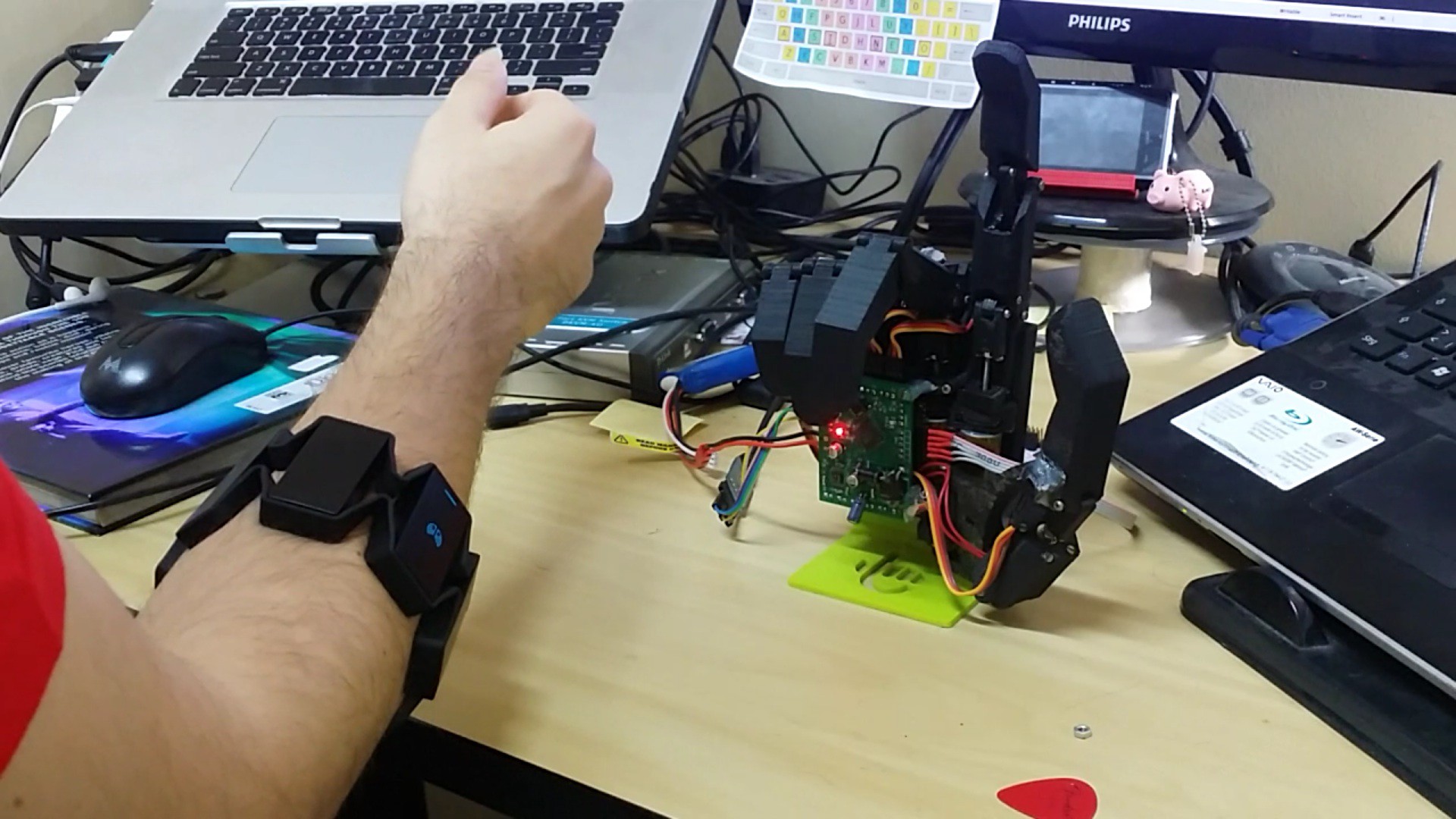
In the meantime, (just for fun) I ran some tests on the current biohand prototype. I've interfaced it with Myo Armband, a great off-the-shelf intelligent EMG sensor, using Niklas Rosenstein's python bindings. The setup requires a PC or smartphone to be connected to the Myo, as it cannot be directly connected to the biohand's ARM Cortex-M3 processor (not in any way I'm aware of).
Check the video on Instagram, or click the pic below to see it :)
-
Thesis presentation video
09/13/2015 at 14:56 • 0 commentsThe last couple weeks have been a bit chaotic, and I ended up having little time to work on the Biohand.
In the meantime, I've presented my thesis. I presented an overview of the Biohand's development, some assembly stages and tests. There you go:
(english subtitles available)
-
First tests with the control board
08/31/2015 at 13:02 • 0 commentsI've received the finished control boards for the biohand about 3 weeks ago. Due to some time constraints, I finished the board and minimal test program for the STM32F103 only during the last week. Despite two minor pinout mistakes on the board (that I've managed to work around), it worked nicely.
Check the board demo video on Instagram.
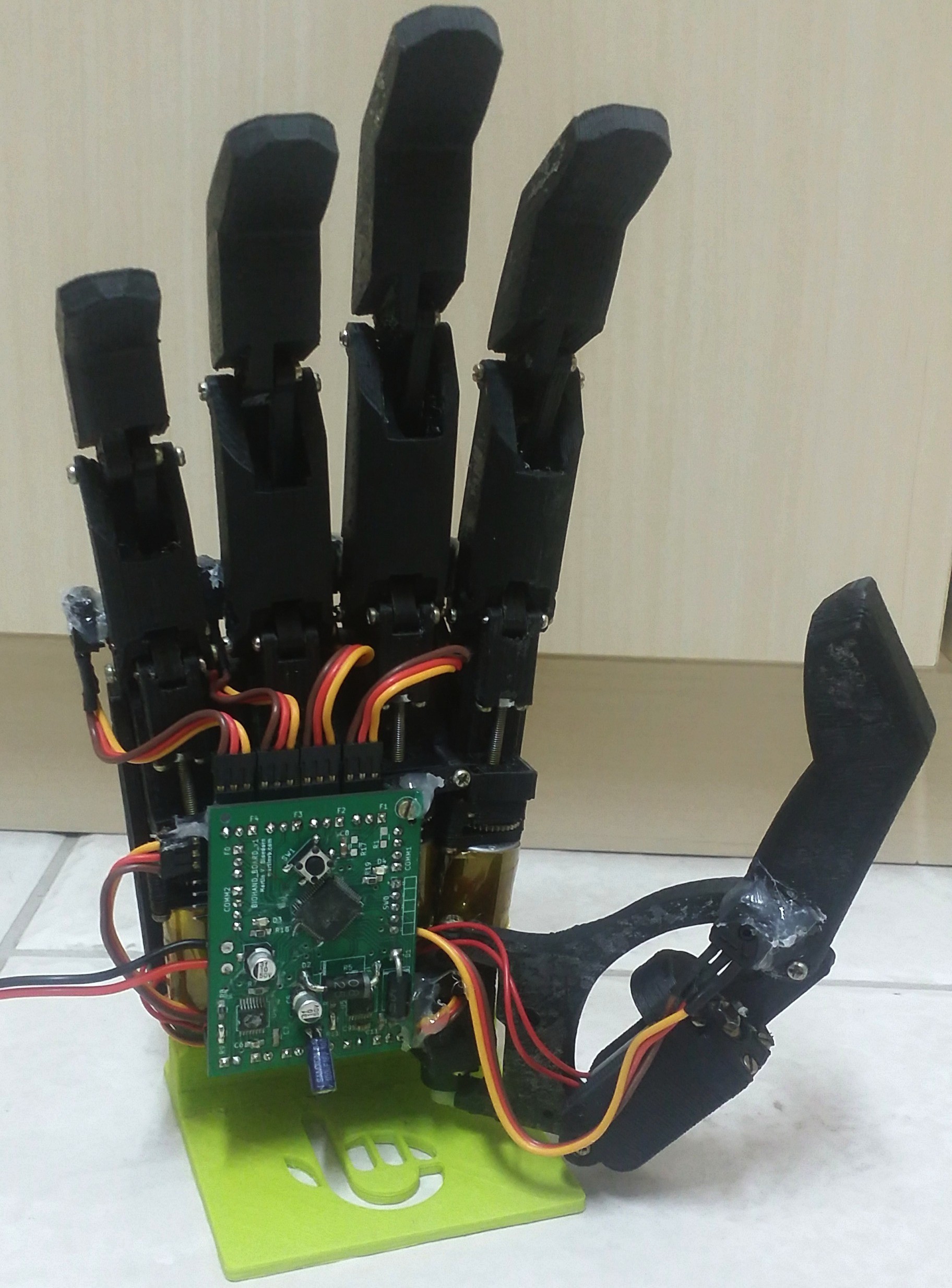
The board was attached to the palm, as shown below:
At some point, this seemed like a good idea. However, the attachments I designed for the board didn't worked out as well as planned (ergo the hot glue all around). Also, the board makes the assembly thicker than I've planned, so adding another layer of a 3D-printed protective cover wiill make the hand too large.
So, I'm already working on an obvious fix; swapping the board to the "back" of the hand, instead of the "inner" palm. I'll post a sketch as soon as I come up with a consistent idea.
'til next time!
-
Short-term To-Dos
08/17/2015 at 18:45 • 0 commentsAs mentioned before, I've spent the last month mostly working on my thesis (about biohand). Now that I've finished it, I finally have some spare time to invest in the project again. I tought I'd briefly list some of the 'To-Do's I have planned for the upcoming two/three weeks:
- In the previous logs I've mentioned that the custom control PCBs had arrived from the board house. They are now fully soldered and functional, but the processor (STM32F103, an ARM Cortex M3) still has to be programmed to offer minimal functionality (drive the motors with PWM, drive the micro RC servo on the thumb's base, etc).
- Once the ARM is programmed, a small frame will be printed to hold the control board on the biohand's palm. All wiring (motors, servo and potentiometers) will be hooked up to the control board.
- As clearly visible in the pictures, there's still no cosmetic covering. The motors and internals are visible and unprotected. A proper cover will then be designed/printed to enclose the biohand's palm.
Other modifications are planned in the long-term future too; the thumb mechanism will be fully replaced and the control board will undergo a large revision. However, these more significant changes will only take place after the aformentioned short-term goals are properly consolidated.
-
First video!
08/17/2015 at 17:57 • 0 commentsI recorded a small video with biohand's basic functionalities at the moment. The main control board is still being programmed, so moving all 5 motors + RC servo in the hand isn't currently possible.
In the video, a standard Arduino controls the thumb's servo and two DC motors, using an Rugged Motor Driver shield (that has the same DRV8801 drivers employed in the custom board).
As soon as the complete board gets minimally programmed and hooked up to the prototype, I'll post another video.
-
Some tests and results
08/17/2015 at 13:21 • 0 commentsAs a part of my thesis on the biohand, I ran some relevant tests (mostly still with no control board, which came in a few days later). Some of these tests are presented briefly here. For more detail, check my thesis! :D
Prehensions
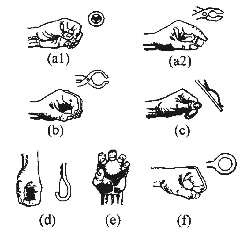
(Weir et al., 2003) presents a minimal list of required hand grips (prehensions) to accomplish the majority of the Activities of Daily Living (ADLs). This list encompasses a total of 7 different poses, shown below:
![]()
They are:
- a1) Tridigital palmar prehension (tripod grip)
- a2) Bidigital palmar prehension (pinch)
- b) Tip prehension
- c) Lateral grip
- d) Hook grip
- e) Spherical grip
- f) Cylindrical grip (power grip)
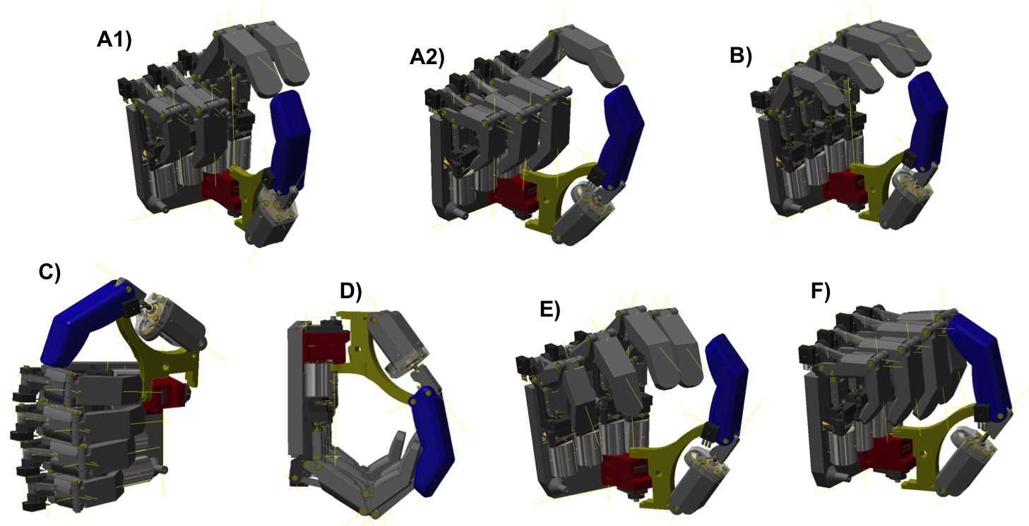
The image below shows the prototype's CAD model implementing this minimal set of prehensions (numbering is equivalent to the figure above):
![]()
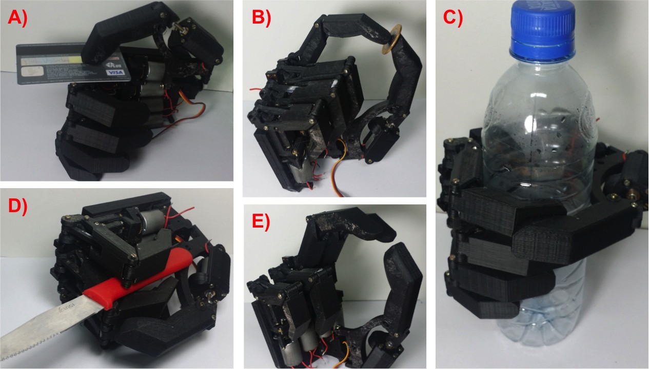
With the 6 active Degrees of Freedom of the biohand, the list could be achieved with no problems. Following the CAD proof of concept, the poses were tested on the prototype itself. The image below shows some of the tested grips:![]()
Those are:
- A) lateral grip
- B) bidigital palmar prehension
- C) cylindrical grip
- D) adduction grip: using the space/angle between adjacent fingers to hold thin objects.
- E) bidigital palmar prehension
Load test
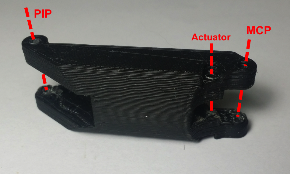
It's a know fact that parts printed in an FDM 3D-printer have stronger bonds inside layers than between them (an interesting study shown here). All parts in the biohand take advantage of this fact: they are designed to be printed aligned to the printing bed in such a way, that the main stress and load gets distributed along the layers.
For example, the image below shows the proximal phalanx of the index finger. The red lines show were the phalanx connects to the MCP (metacarpophalangeal) and PIP (proximal interphalangeal) joints, as well as the linear actuator that moves the finger. The part gets printed with the orientation shown in the figure:
![]()
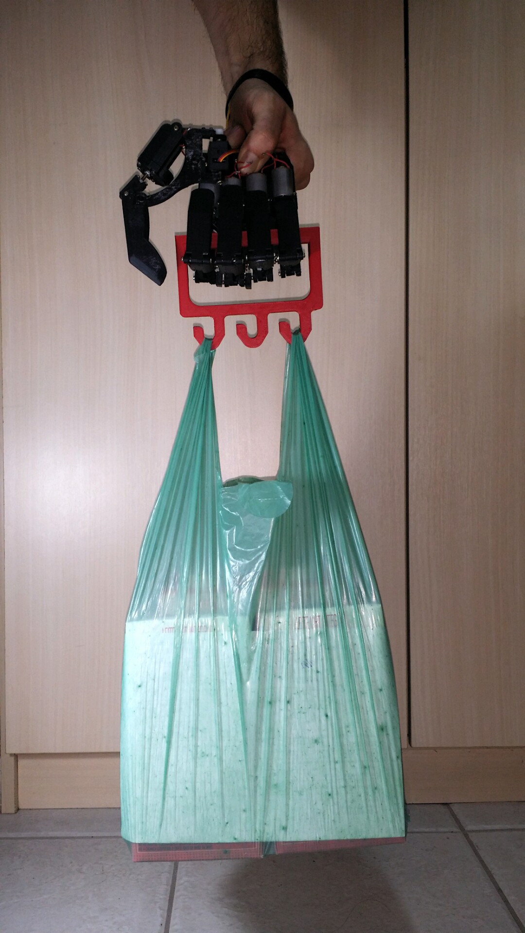
This grants an increased robustness. No destructive tests were conducted, but the test below shows the biohand succesfully whitstanding a load of 40N with no signs of demage:
![]()
The test was carried out with no power supply, since the fingers employ a non-backdrivable mechanism.
Speed, strenghts and weight
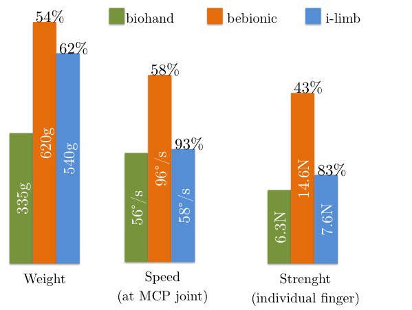
Upper-limb prosthetics still have a hard time achieving speeds and strenghts comparable to those in human arms and hands. To contextualize the biohand's streght, speed and weight, it shall be compared to two of the market-leading devices: the i-limb and the bebionic v2 (the previous version of the current v3 model). The data from these devices is based in the wok of (Belter et al., 2013):
![]()
The biohand weights in at approx. 335g (planned with the control board and cosmetic cover). This represents 54% and 62% of the the commercial prosthetics.
The index' angular speed, when measured at the MCP joint (at the base of the finger), reaches a peak of 56°/s, which is 58% and 93% of the other two devices.
Lastly, an individual finger of the biohand is capable of exerting up to 6.3N*, which represents 43% and 83% of the commercial devices.
Considering that the biohand uses modified RC servos as linear actuators for each finger, I can't say I'm not pleased with the results. Four fingers working simultaneously can exert more than 36N in a prehension. This is sufficient for the majority of lighter ADLs, as stated in (Smaby et al., 2004).
The reduction in weight is also very relevant. The work by (Pylatiuk et al., 2007) shows that excessive weight is a complaint of most amputees carrying some type of prosthetic device.
* The force test used only 60% of the biohand's nominal tension, to avoid motor demage during stall (for the maximum-force tests).
Cost
Lastly, one of the great thriumphs of the biohand is, in my opinion, its very low cost. With the prototype almost completed, the cost table can be calculated as follows:
Item Cost per unit (USD) Quantity Subtotal (USD) Standard RC servo 12,95 5 64,75 Micro RC servo 9,95 1 9,95 Black ABS plastic (filament) 19,19 (kg) 155g 2,97 Other hardware costs (e.g., screws, glue) - - 5,00 STM32F103 processor 7,14 1 7,14 DRV8801 motor driver 3,15 5 15,75 Overall electronic costs (e.g., manufacturing) - - 15,00 2S / 1000mAh LiPo battery 11,49 1 11,49 Total: 132,05 Prices were checked in Amazon for the LiPo battery, in OSHPark for the board costs and in 3ders for the average spool price.
With a total price of approximately USD 132,05, the biohand costs 200 times less than the average commercial myoelectric/robotic prosthesis.
Bibliography
Weir, R. F. et al. Design Of Artificial Arms and Hands for Prosthetic Applications. 2003.
Belter, J. T. et al. “Mechanical design and performance specifications of anthropomorphic prosthetic hands: A review”. In: Journal of Rehabilitation Research & Development (2013).
Smaby, N. et al. “Identification of key pinch forces required to complete functional tasks”. In: Journal of Rehabilitation Research & Development (2004).
Pylatiuk, C., S. Schulz, and L. Döderlein. “Results of an Internet survey of myoelectric pros- thetic hand users”. In: Prosthetics and Orthotics International (2007).
-
Boards
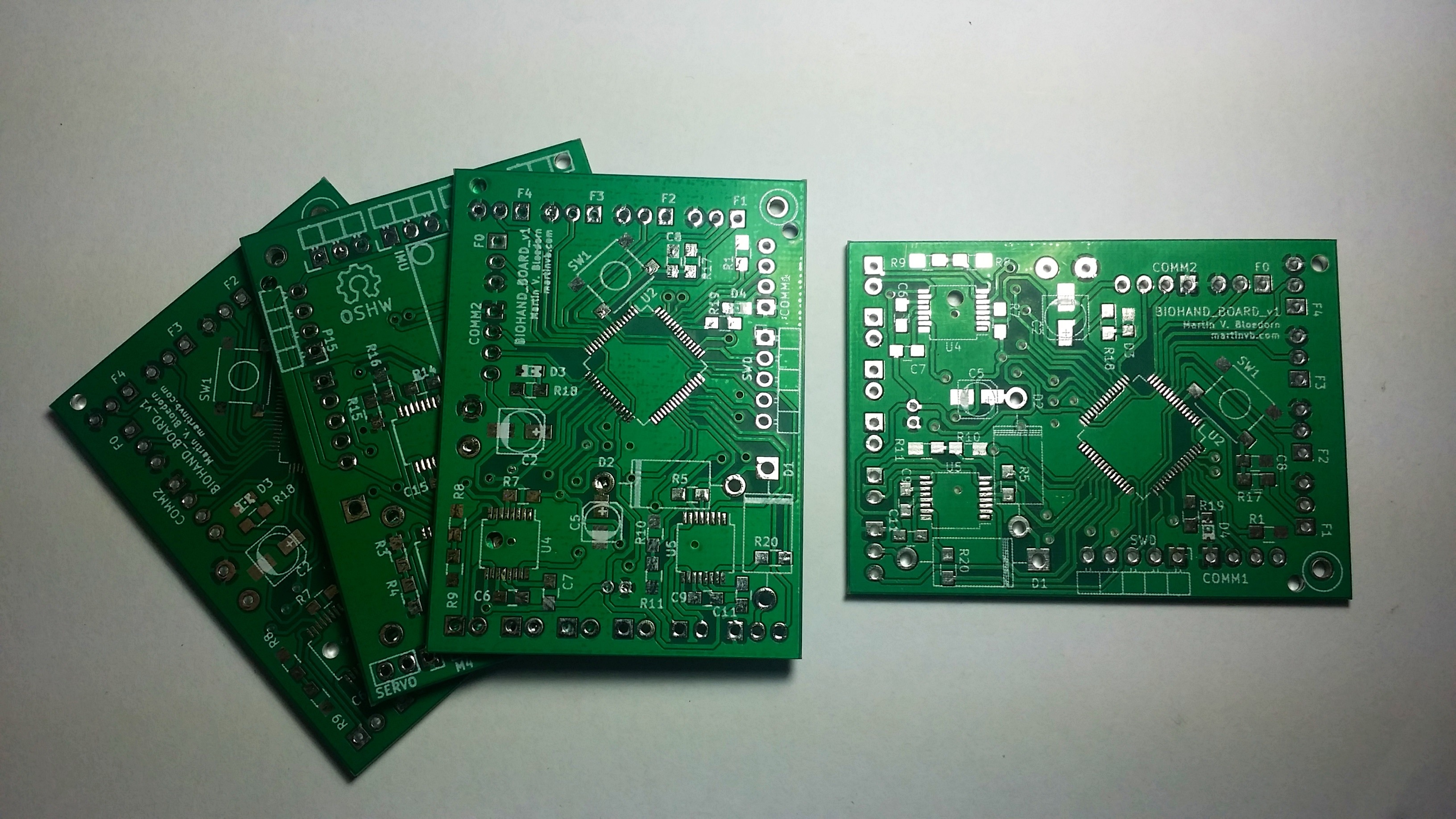
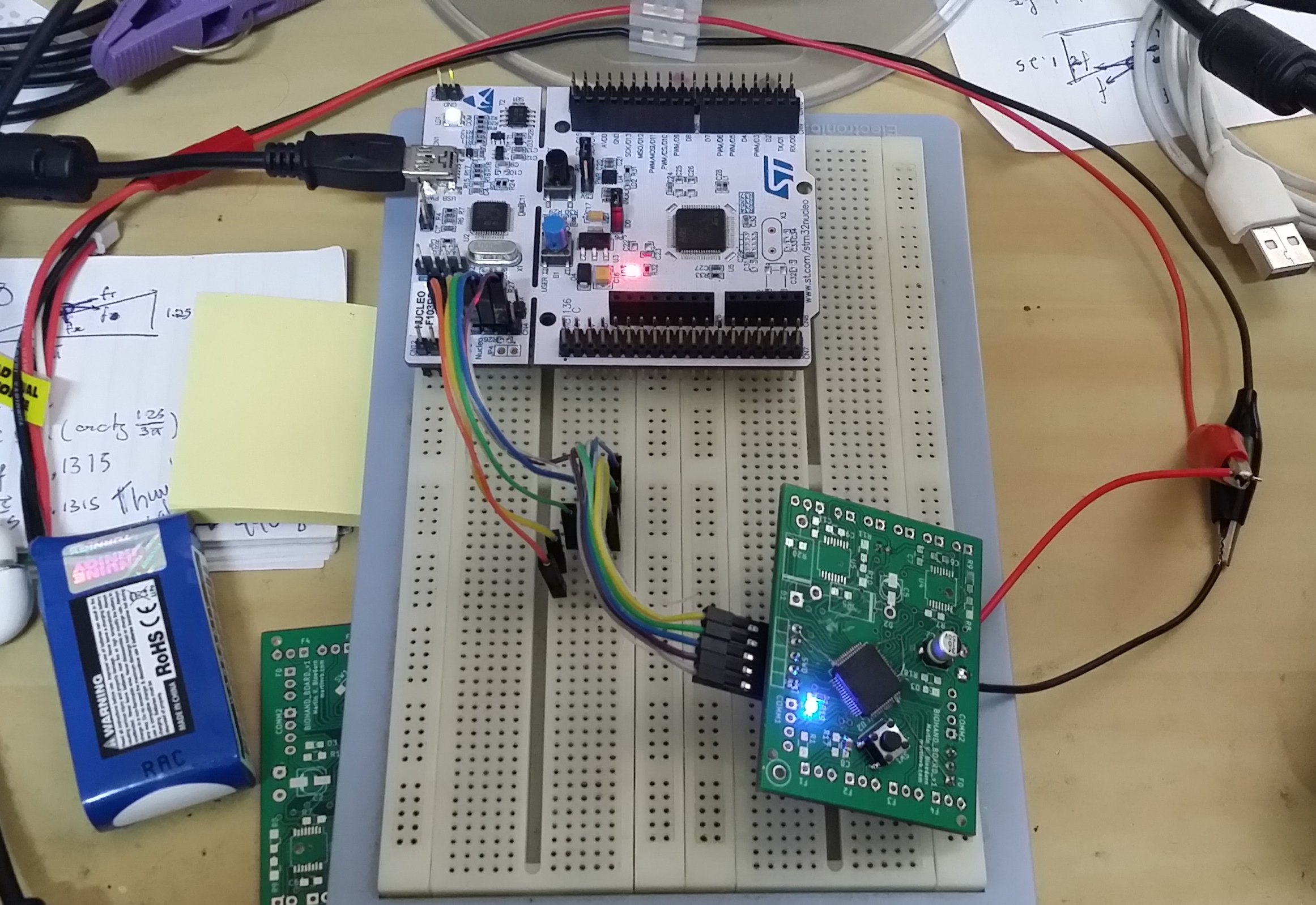
08/15/2015 at 22:01 • 0 commentsSo. Finished the bulk of my thesis, which frees time to work in this project again. Almost synchronized, the first iterations of the biohand's control boards arrived from the board house!![]()
I rushed to test them. But yea. With all those small piched components, I didn't got around milling a version in my CNC before the design was sent off for manufacturing. So, it was kind of all-or-nothing. And as it's (almost) always the case, I soon discovered some mistakes. Namely, I swapped two VDD/VSS pairs from the STM32 processor. [...] It took me around 24h to find and solder a workaround and get a minimal setup (processor + regulator + caps) to work. LED blinking in the next pic:
![]()
Time to keep soldering (and eventually spotting other dumb mistakes, *sigh*).
BTW, more info on the project will soon be available on my personal page.
'til next time!
-
Looking a bit sharper
07/18/2015 at 20:30 • 0 commentsI'm currently writing my thesis (about the biohand, BTW), a process that will take me at least a couple more weeks. Thus, I haven't had much time to further develop the hand itself. For now;
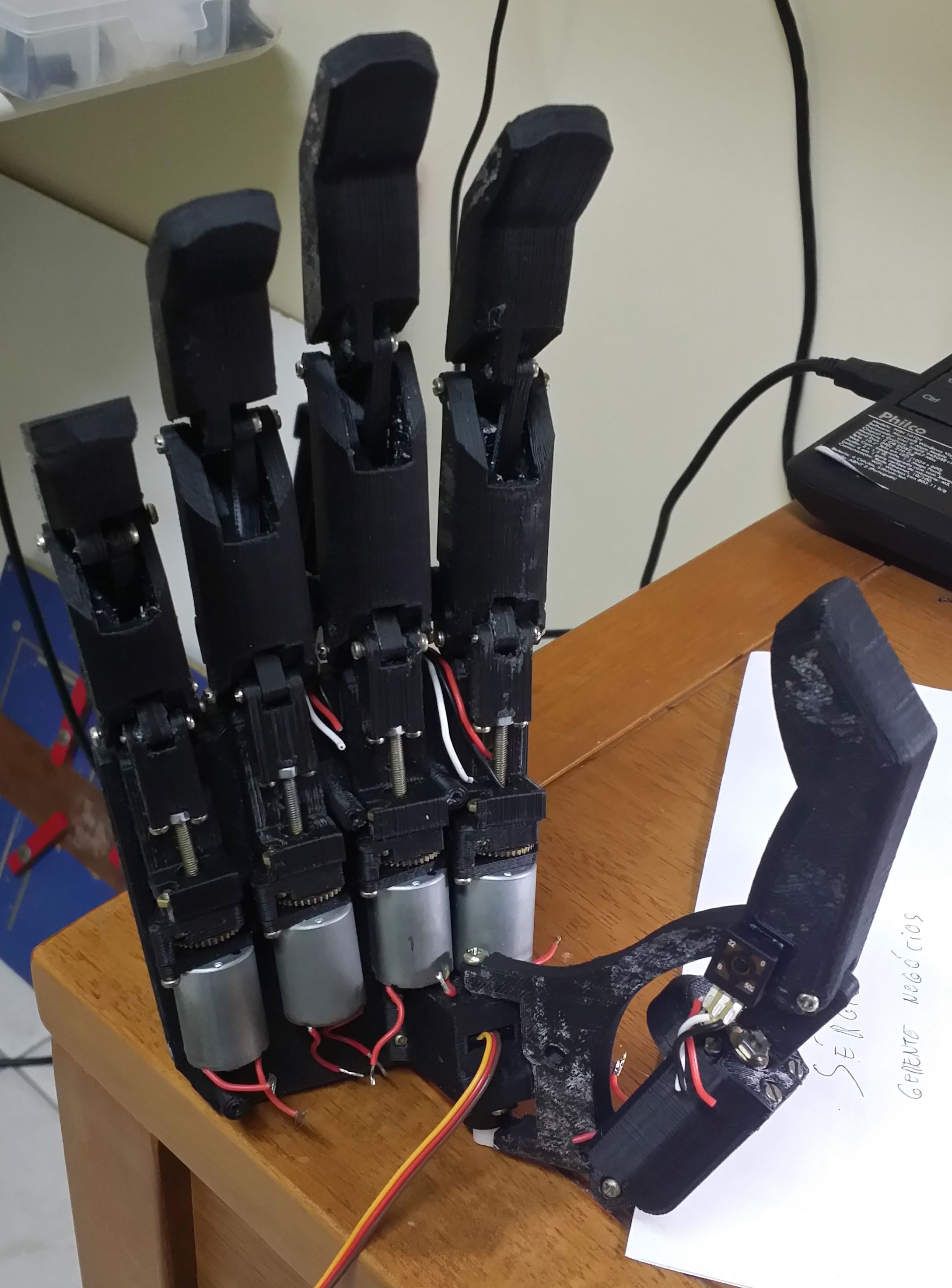
- Electronics are in the oven. Sent out my boards for manufacture with a local supplier.
- Replaced the somewhat odd red-test-thumb with a more definitive (and cool looking) dark one.
That's it, for now (sadly). I'll leave some pics on the hand's current state. I'll also try to upload a video of a simple function demo in the near future. 'til next time!
![]()
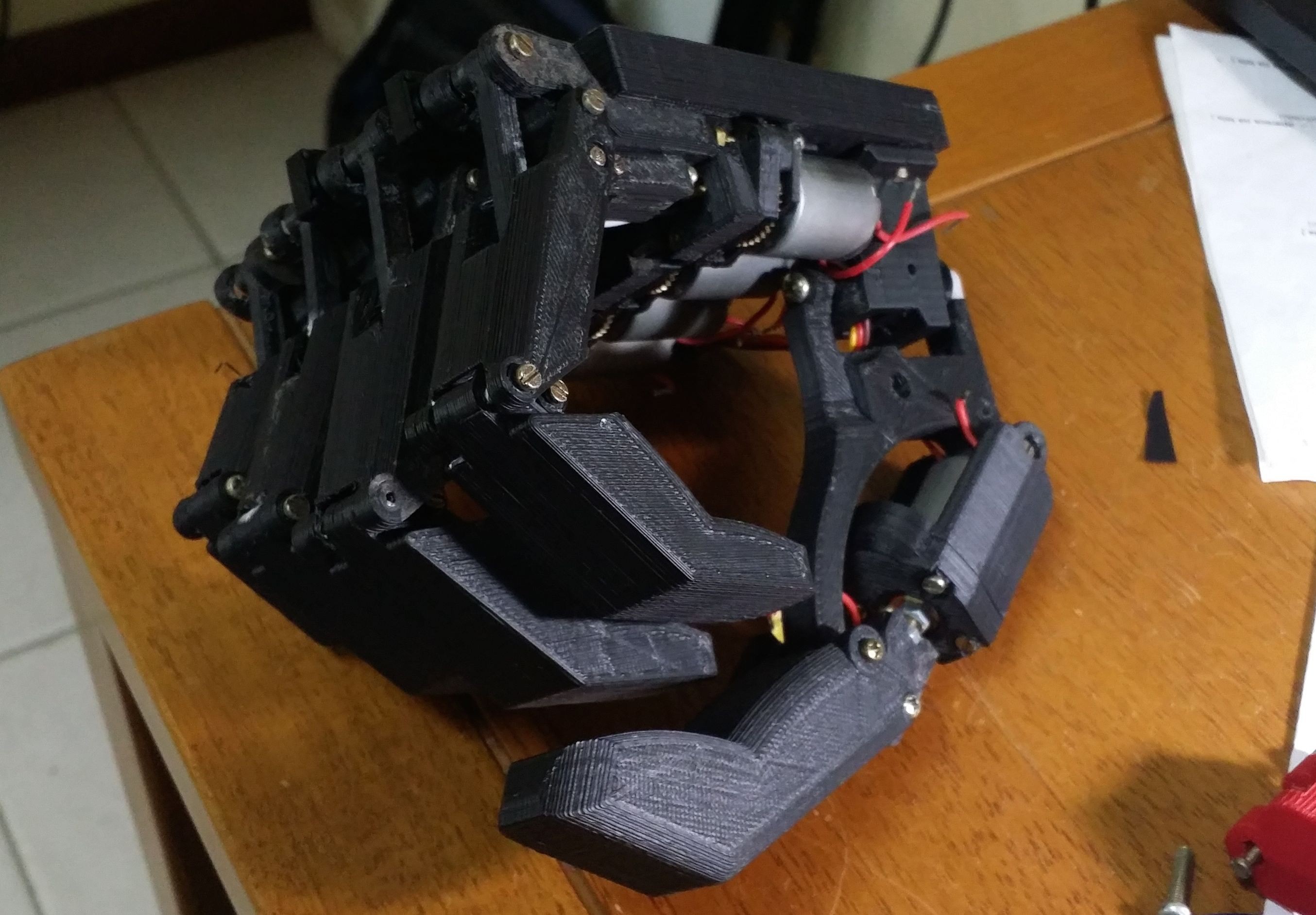
Clenching a fist:
![]()
biohand - Low cost 3D printed hand prosthesis
Development of a robust low cost 3D printed hand prosthesis using off-the-shelf components.
 Martin Vincent Bloedorn