Antti Lukats
-
Creating IP Cores
08/30/2015 at 16:29 • 1 commentStep 1
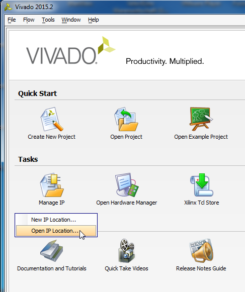
Start Vivado, Click on Icon Tasks, Manage IP
![]()
Select either New IP Location or Open IP Location if you have already made some IP Cores
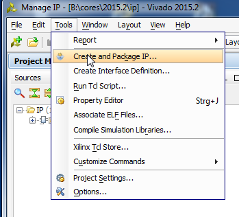
Step 2
![]()
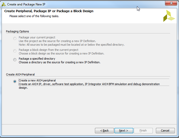
Step 3
![]()
Select AXI Peripheral
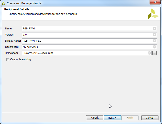
Step 4
![]()
Pickup some name
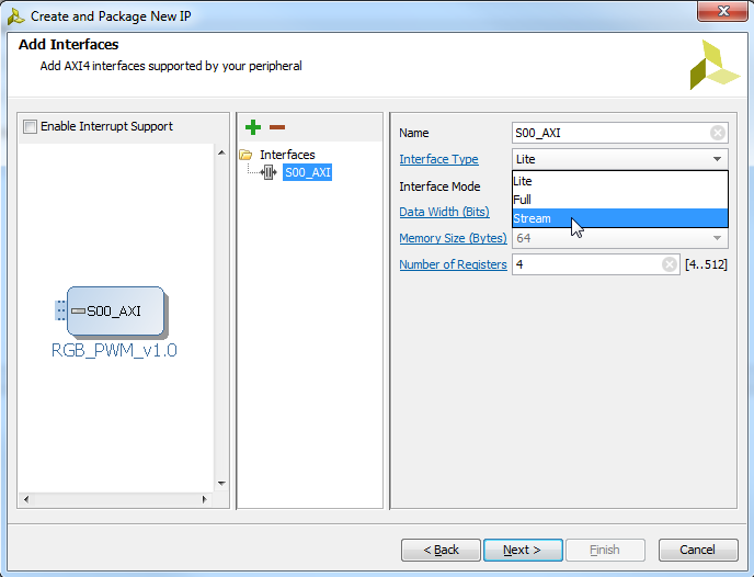
Step 5
![]()
Sekect Stream, next and finish
Step 6
![]()
Edit in IP Packager
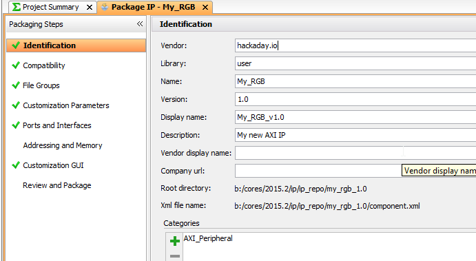
Step 7
![]()
Pickup some "vendor" VLNV to your liking, like hackaday.io !
Step 8
![]()
Remove the wizard generated AXI Stream "dummy" from the IP Core project
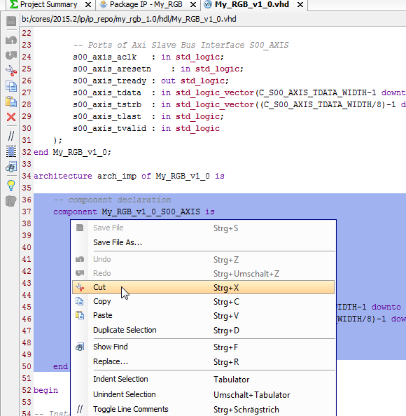
Step 9
![]()
Remove the component declaration (to the file we just removed from project)
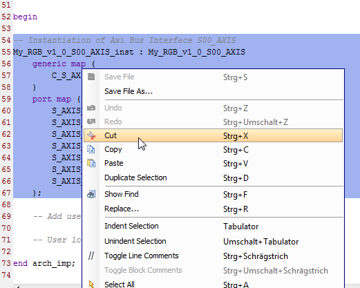
![]()
Remove the component instantion as well
Step 10
![]()
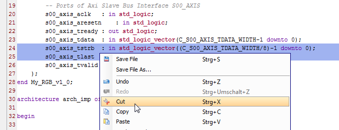
Delete TSTRB and TLAST ports we do not need them
STEP 11
Copy paste s00_axis_ready and add: <= '1'
s00_axis_tready <= '1';With this we tell that we are ALWAYS ready.Step 12
![]()
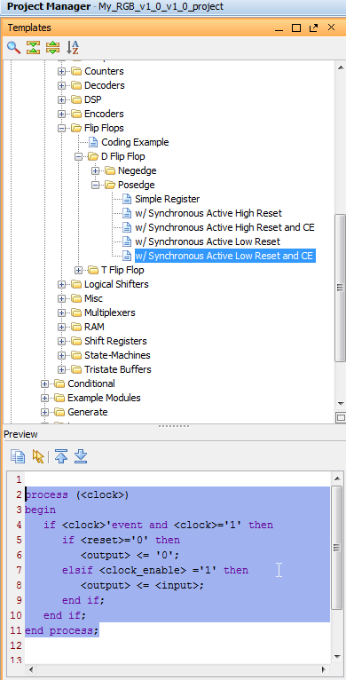
Select Templates, and copy the template body in the IP main body, and replace using copy paste
<clock> with s00_axis_aclk
<reset> with s00_axis_aresetn
<clock_enable> with s00_axis_tvalid
process (s00_axis_aclk)
begin
   if s00_axis_aclk'event and s00_axis_aclk='1' then
      if s00_axis_aresetn='0' then
         <output> <= '0';
      elsif s00_axis_tvalid ='1' then
         <output> <= <input>;
      end if;
   end if;
end process;
Like this, now we have created a Latch that samples data sent to us, data that we want to use for RGB LED PWM Control.Step 13
We could have done it earlier, but lets do it now, we use some copy paste again, to get one Output to our IP Core
![]()
We copy and paste this, and change it to say LED_R, then make the same for G and B too
		-- Users to add ports here
        LED_R	: out std_logic;
        LED_G	: out std_logic;
        LED_B	: out std_logic;
		-- User ports ends
like thisStep 14
Now we should implement the PWM control, but for testing we make on off control only, then we can later add the PWM.
Let say we would like to use 8 bit PWM later, so we have a byte for each color, for on-off control we use the MSB bits.
So we send D7 to Blue, D15 to Green, and D23 to Red LED, first some copy and paste again, to have code like this
process (s00_axis_aclk)
begin
   if s00_axis_aclk'event and s00_axis_aclk='1' then
      if s00_axis_aresetn='0' then
          LED_R <= '0';
          LED_G <= '0';
          LED_B <= '0';
      elsif s00_axis_tvalid ='1' then
         LED_R <= <input>;
         LED_G <= <input>;
         LED_B <= <input>;
      end if;
   end if;
end process;
the first 3 assignment assign the default RESET value of 0 to the RGB LED outputs. More copy paste, and we need to type the brackets and numbers!architecture arch_imp of My_RGB_v1_0 is begin s00_axis_tready <= '1'; process (s00_axis_aclk) begin if s00_axis_aclk'event and s00_axis_aclk='1' then if s00_axis_aresetn='0' then LED_R <= '0'; LED_G <= '0'; LED_B <= '0'; elsif s00_axis_tvalid ='1' then LED_R <= s00_axis_tdata(23); LED_G <= s00_axis_tdata(15); LED_B <= s00_axis_tdata(7); end if; end if; end process; end arch_imp;We are done here. No more code is needed. Do not forget to save the file..Step 15
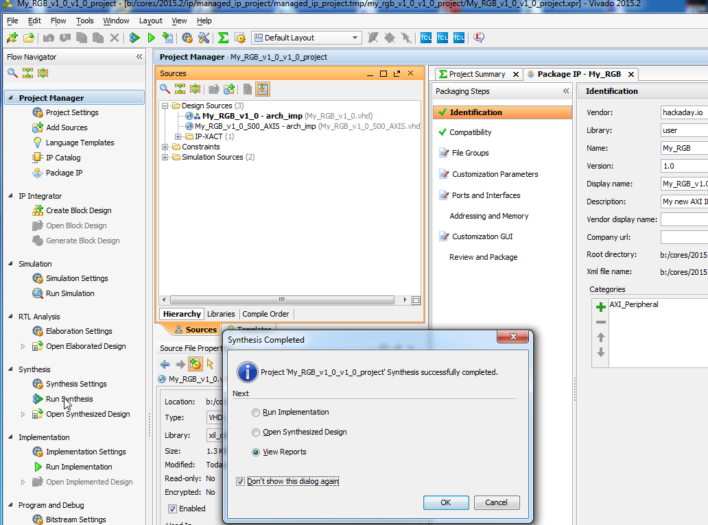
Click on Synthesis > Run Synthesis to check that it is all OK
![]()
Step 16
At the right there are items marked red, click on them and say each time MERGE :) until all turns green!
![]()
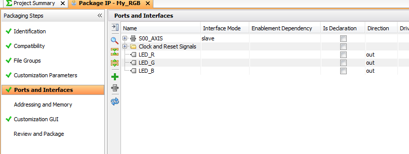
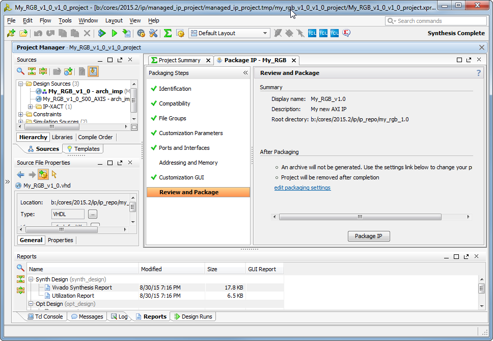
Step 17
Select Review and Package, and click on Package IP
![]()
Choose "Close Project". We are Done, the IP Core is READY to be used in Vivado IP Core Catalog.
Next short walk-though how to use it.
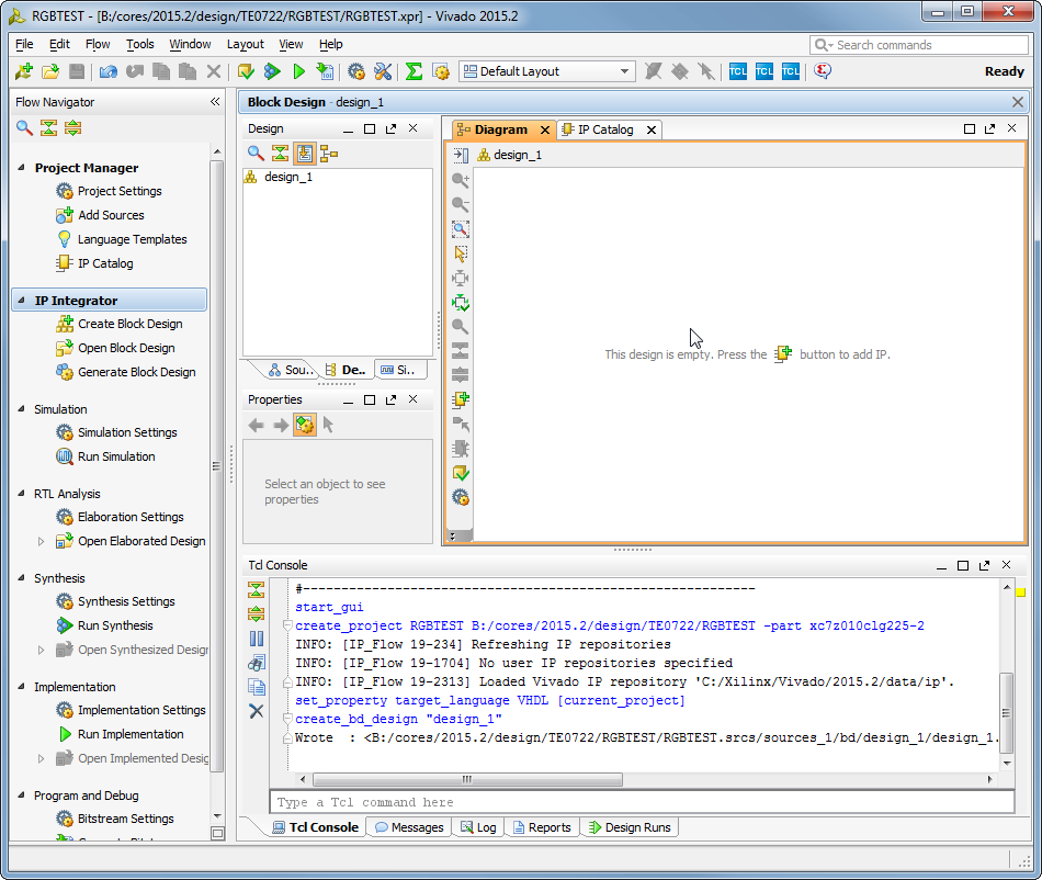
Step 18
Create a new Vivado Project, select any part (or any part that your license does allow), next next just to get some project created and opened. Click on IP Integrator > Create Block Design, OK
![]()
Do no click on the + Button yet, we need to tell Vivado where is our IP Core Catalog..
IP Catalog, select Add Repository choose the place where you created the RGB IP Core!
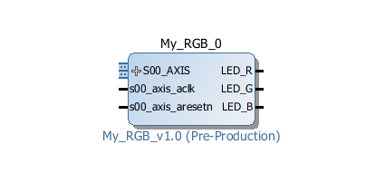
Now click on the + button to add IP, type rgb in search box, and doubleclick
![]()
Our IP is now inserted into new SoC design!
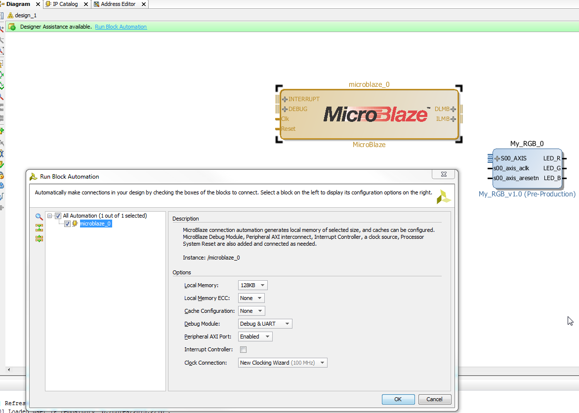
Step 19
We need a Processor, preferable a free one, so Ctrl+I or right mouse-click, and start typing "micro.." and doublick on MicroBlaze
![]()
Then click on "Run Block Automation" and make selections as shown:
![]()
And click OK
![]()
We have now RGB IP Core and full 32bit Risc based SoC including RAM and JTAG debug and virtual JTAG UART Console
Step 20
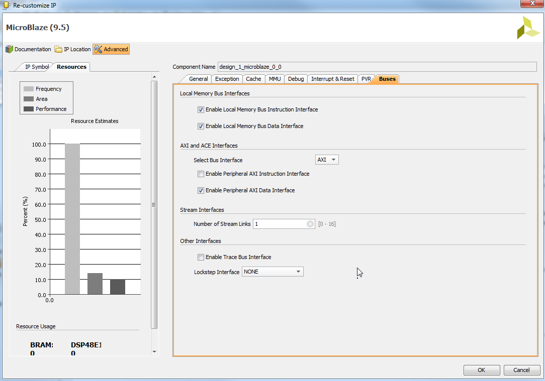
We need to interface our IP Core to the Processor, so we double click on MicroBlaze, select Advanced, buses and change the number of Stream Links from 0 to 1
![]()
Click OK
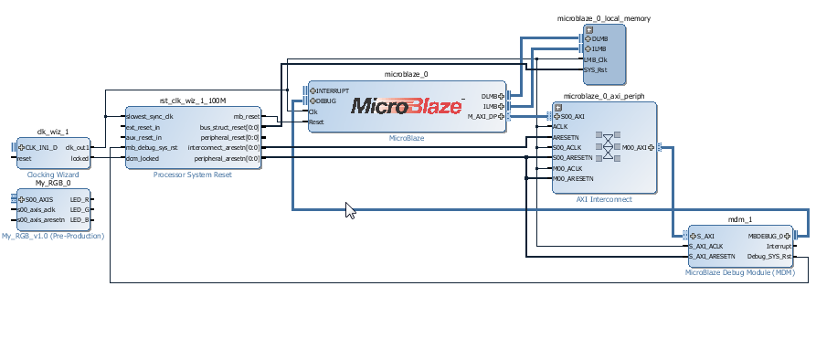
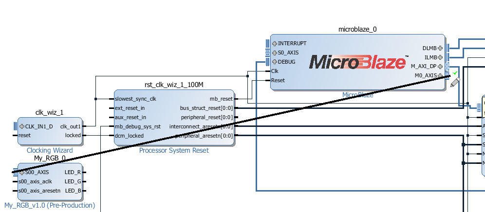
Now we are ready to connect RGB IP to the Processor, use mouse drag like this..
![]()
clock and reset lines need to be connected manually (there is a reason for this..)
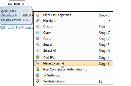
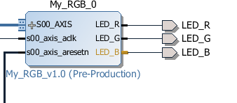
Now we have to connect the RGB signals from the Processor to the real LED's right? Right click and choose "Make external" three times..
![]()
![]()
We are almost done.
I Skip some steps here..
Step 21
In Xilinx SDK we write
#include "fsl.h"This will include API for the special instructions to work with AXI4-Streams as if they would be custom CPU instructions.void SetRGB(u8 RED, u8 GREEN, u8 BLUE) { putfsl(RED <<16 | GREEN << 8 | BLUE, 0); }Now we define a function to control our IP Core
int main()
{
    print("Hello Hackaday\n\r");
    SetRGB(128, 128, 128); // make all ON
    while (1);
}
Thats all folks.We did create our IP Core, added it to SoC system, and we have C code that talks to it. We are ready to debug the Software on the Hardware we designed in the steps earlier.
The skipped steps are mostly click click and boring, will be explained later in details, in this LOG the main topic was creating the IP Core what is included with all steps as required.
-
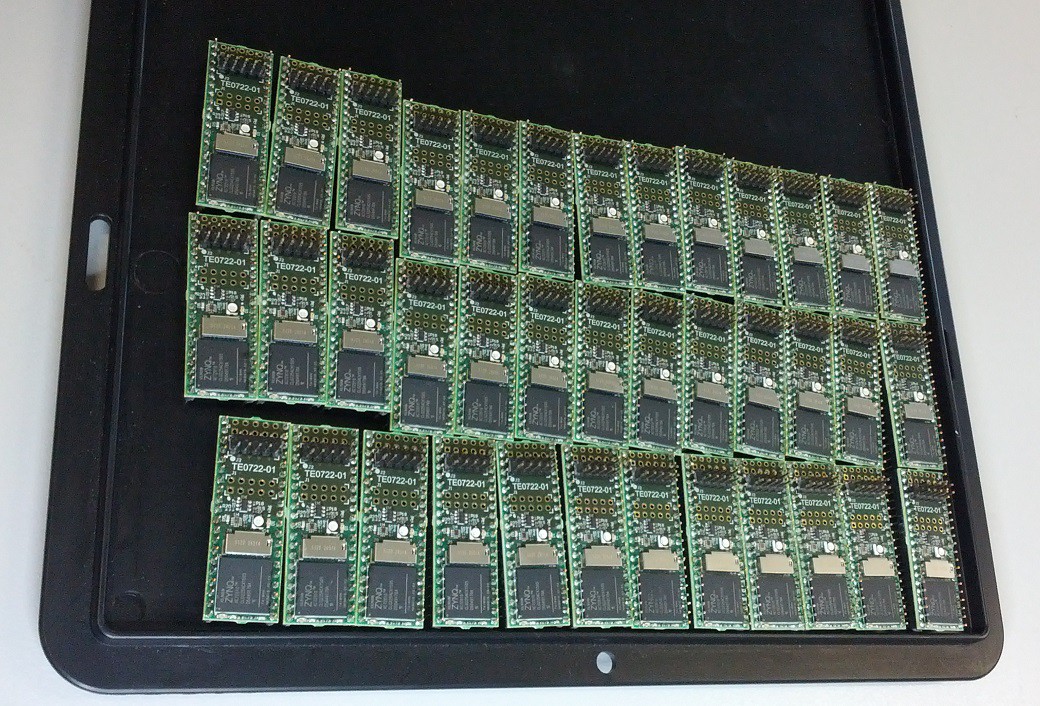
First Production Batch ready
08/20/2015 at 07:47 • 0 comments![]()
Some propellers are ready. Yesterday also first time got the Propeller HDL code first time tested on Zynq, all previous test I had done with Artix not Zynq devices.
-
First production batch
08/17/2015 at 20:17 • 0 commentsIs actually ready in the factory, I did see it today. SMD assembly is done, Through hole (the pins!) assembly is be in progress.
-
Pushed to github
08/17/2015 at 18:48 • 0 commentsall hardware CAD sources and generated files on Github main repo
-
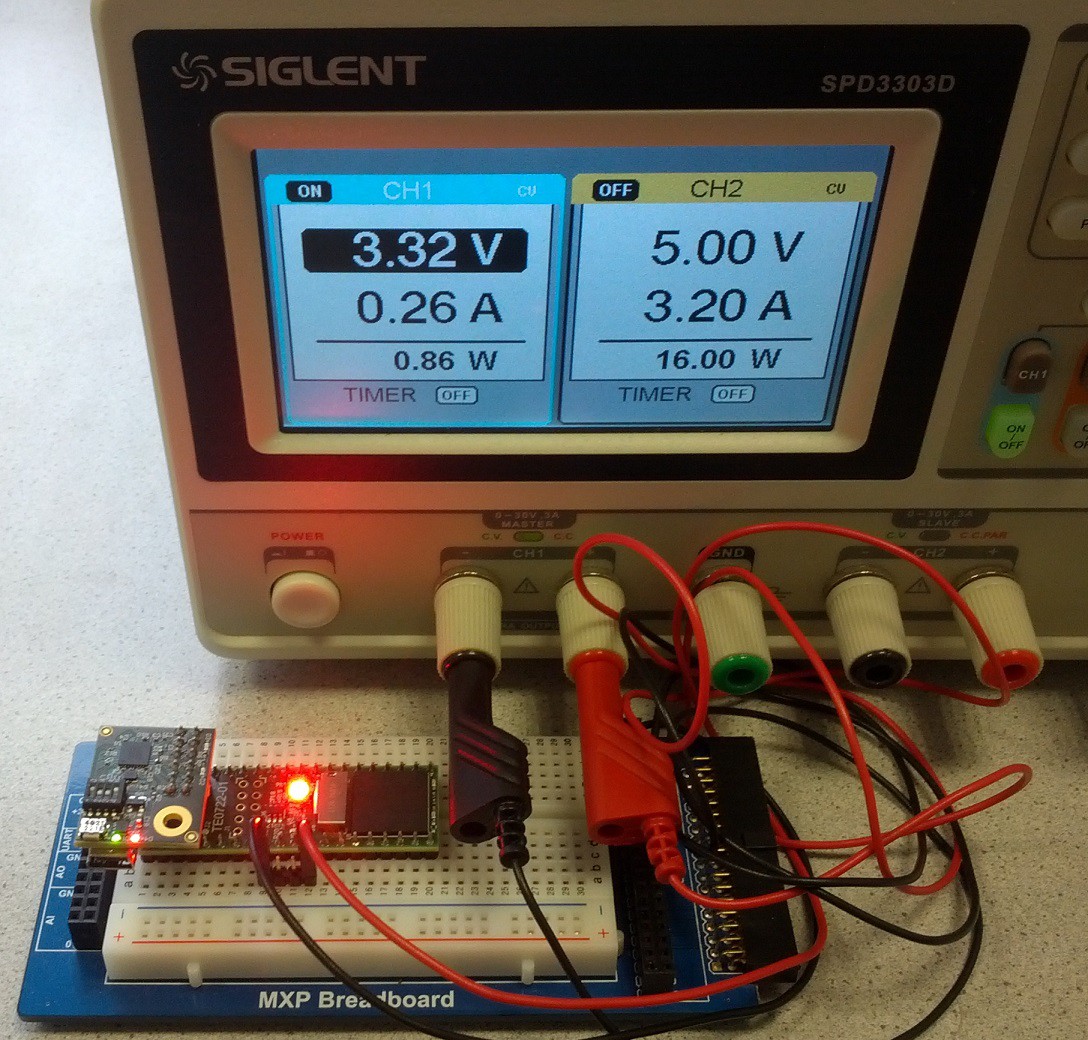
Breadbord setup
08/17/2015 at 17:15 • 0 comments![]()
When it works the power consumption should be less 1W
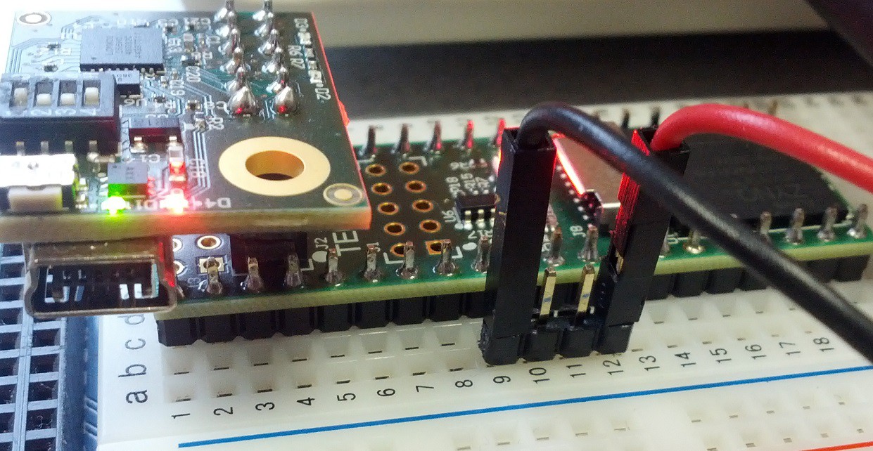
Black is 0V GND and red is +3.3V, also clearly visible are the DIP switch setting on the JTAG adapter![]()
There is 2x5 pin header on the module, the adapter has 2x6 socket header, correct insertion as above.![]()
-
Parallax Development Board
07/22/2015 at 18:52 • 0 commentsGot the Parallax Propeller Professional Development Board today for testing the softprop module. Plugged in and LED's OK, powered and working. Well it sure only means that power pins are correct, but still nice to the softprop on development board for the real propeller DIP40.
Now I have test setup for many things, so it will be easy to test video out and other funny things.
-
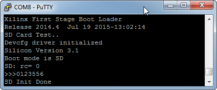
SD test, PROP Code
07/19/2015 at 11:49 • 0 commentsVery first test to read something from SD Card :)
![]()
SD Card init succeeded, open file also. The code does not really load yet anything from SD Card, but the ability to access files from SD is at least proven now.
Propeller V 1.0 verilog code (unoptimized version), results with Vivado 2014.4 standard settings
![]()
A bit more than 50% of LUTs are consumed. It is possible to optimize the prop HDL code to use DSP48, this would save a few LUTS. Fitting 2 Propeller cores may be possible, or one with more COG.
-
USB Analyzer
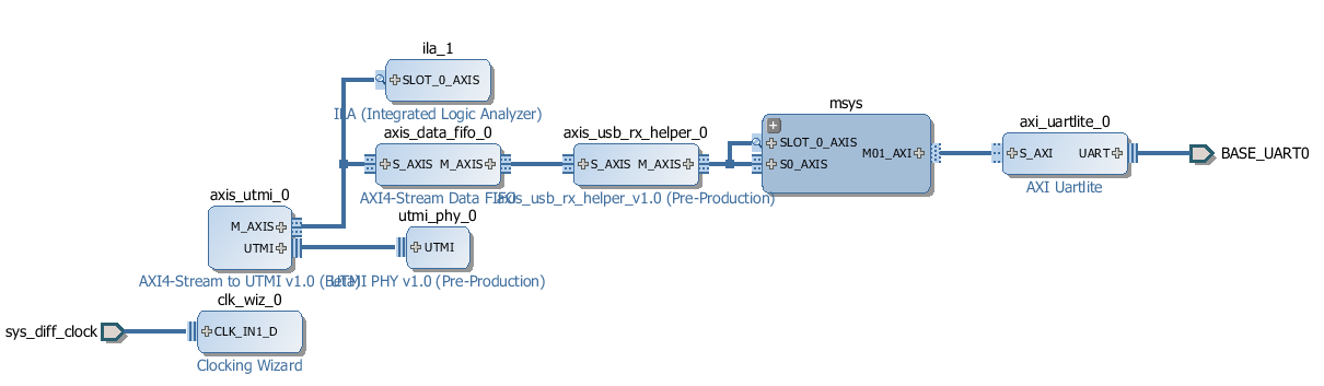
07/18/2015 at 09:08 • 0 commentsThis will be one of ready made ready to use configurations and demo designs for Soft Propeller: USB Analyzer - Full Speed (maybe also LS). There is no extra hardware needed (except maybe ESD protection!).
![]()
This is how it looks if you have created the USB Analyzer application, utmi_phy, axis_utmi, axis_usb_rx_helper are IP Cores that I have not had time to make public yet. They will be available under free license (MIT most likely). The remaining blocks are free IP Cores from Vivado IP Core repository. This design uses 2 FPGA pins as USB receive only PHY and converts the USB traffic into single byte stream.
![]()
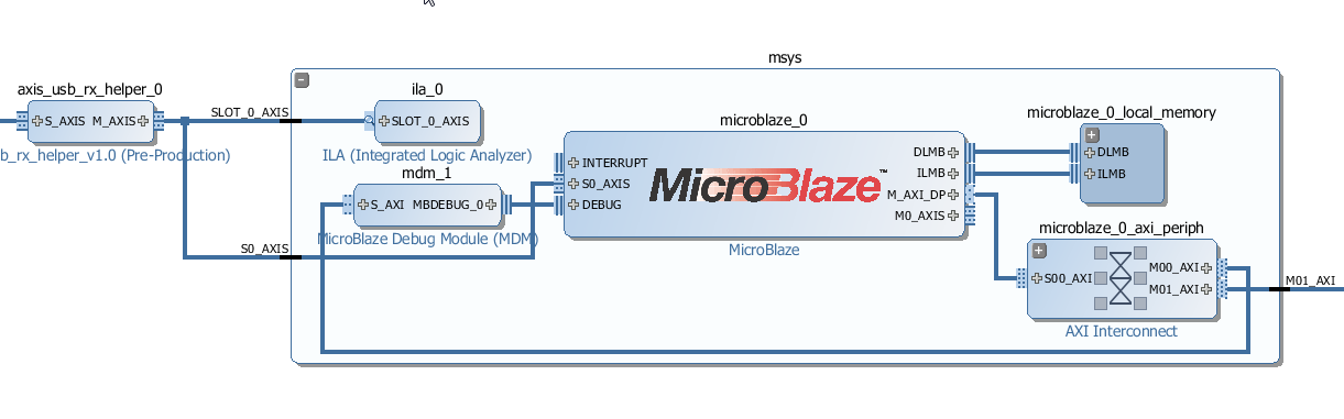
USB log data stream is connected directly to MicroBlaze AXI4-Stream port, and USB log data is read using MicroBlaze custom special instruction.
Note that the 2 onchip logic analyzer IP Cores (ILA) are not requried for the design, I use them only during testing. With Softpropeller the same stream can be read and processed by one of the ARM Cores, MicroBlaze is not needed (but could be used as pre filter processing enginge). Note that MicroBlaze is COMPLETLY free for Xilinx 7 series (for pre 7 series MicroBlaze required a paid license).
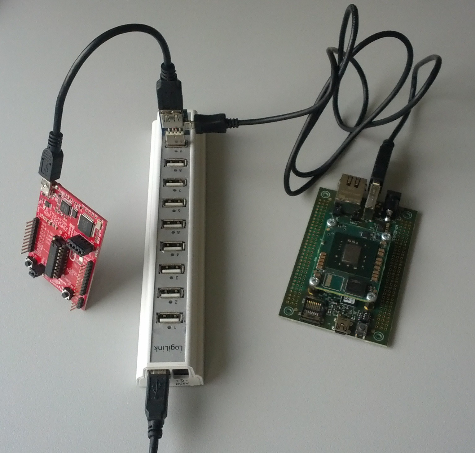
![]()
This is workint setup for the Development of the USB Analyzer system. Inserted into the hub is usb-usb-usb break-out board (a design of mine made many years ago). The RED board is usb device whos comms are to be analyzed (some TI launchnad in this case). The grey area to the right is bare die of Xilinx Kintex K160T.
With this setup the USB DP/DM are directly connected to FPGA I/O Pins with no added ESD protection circuitry, this is eventually deadly for the I/Os, but so far the Kintex has survived all experiments.
For actual USB Analyzer desing the "break out" PCB or connection to physical USB lines should include some protection circuitry.
-
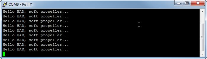
Hello HAD, soft-propeller...
07/17/2015 at 20:46 • 1 commentHello world is usually simple. But it not always works the first time, so it always a good feeling seeing some thing to greet you.
![]()
Here it goes :)
![]()
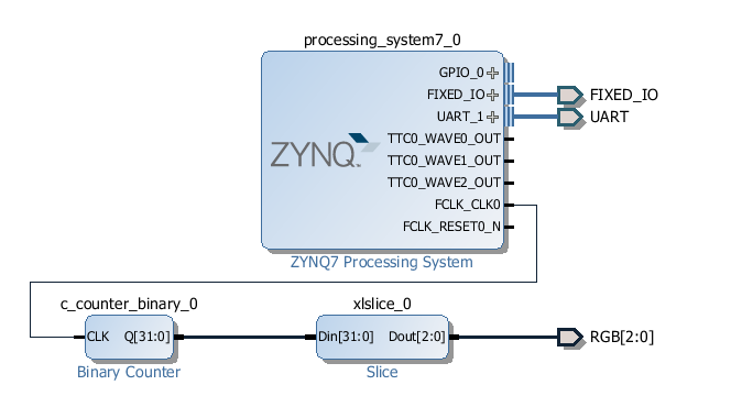
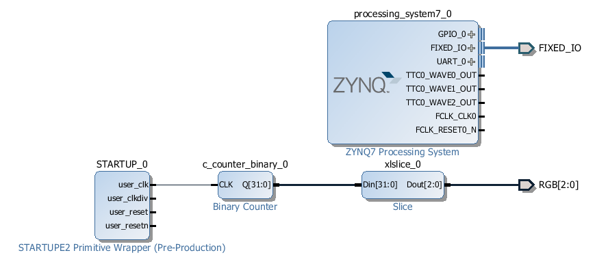
The counter that was clocked from FPGA internal free running oscillator is no clocked from PLL in the PS subsystem, PS UART1 is routed via FPGA fabric to some pins, well in this case to the pins in the JTAG-UART combined debug header-connector.
Maybe the hello could have worked first try also, but I had another Zynq PCB from our oven a few hours earlier today what I had to test (succesfully). Maybe there was no more juice at 2200 hours.
But important is that the DIP40 Zynq mod is alive, loads FPGA and says hello :)
-
We have RGB..!
07/16/2015 at 17:03 • 0 commentsRGB or maybe GBR, we had to replace the RGB as the one we got had different pinout to what was initially designed in.
But after small rework, very first test design with vivado, with pure block design and no use of ARM cores, just worked.
The LEDs are with full brightness, no PWM.
![]()
Very stupid design but it does at least check all LEDs are working. Does now work out of flash too, the FPGA is loaded by ARM cores from SPI flash that is mounted as normal linear Flash. The ARM Cores can execute also directly from SPI Flash...
Soft Propeller
DIPFORTy1 "Soft-Propeller" Zynq-7, Dual CortexA9+ FPGA DIP40 Parallax Propeller I compatibles footprint