-
31Step 31
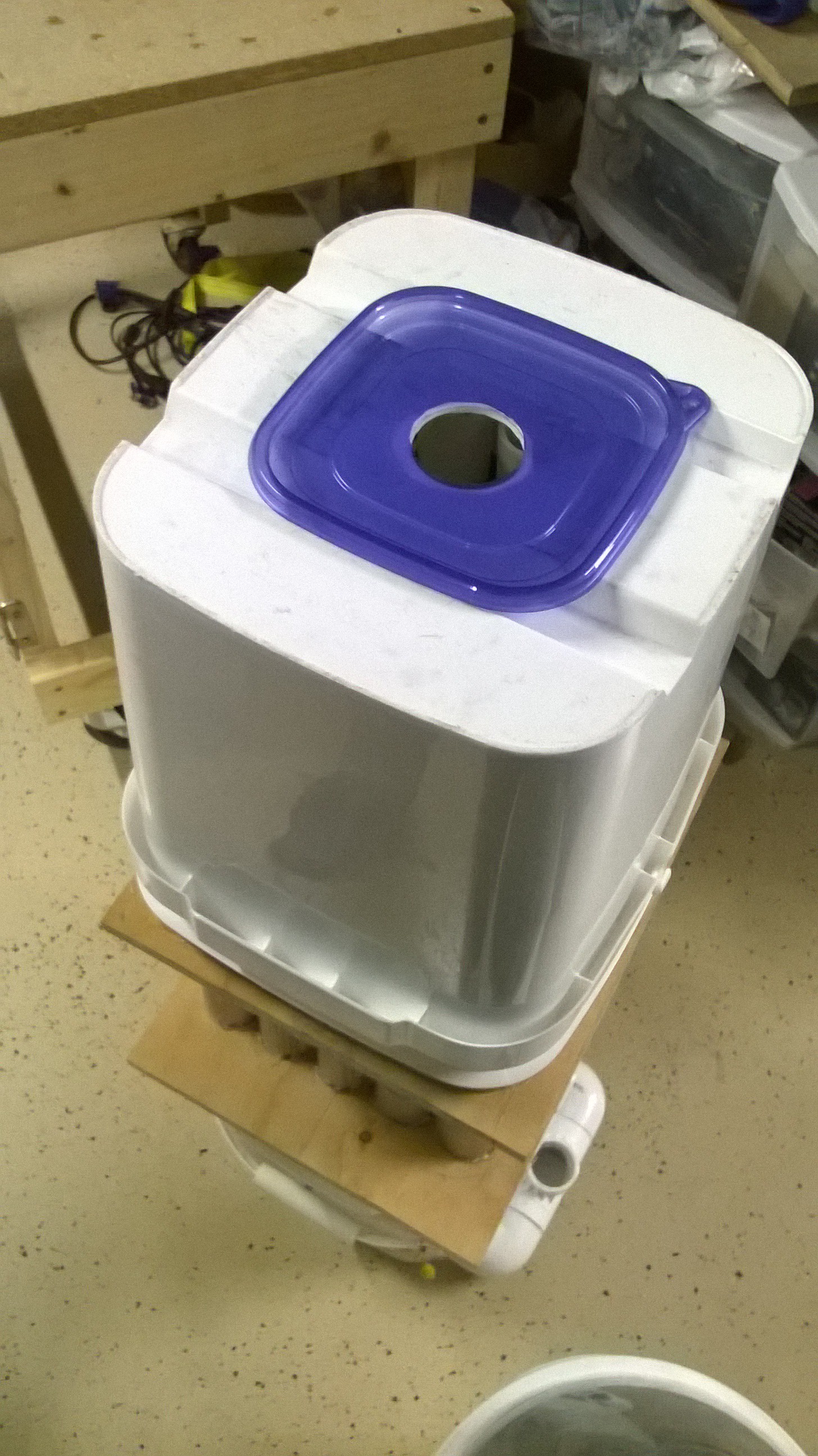
Now glue a lid of a square sandwich container to the top of the hole and drill a 2" hole in lid.
![]() Then cut out the bottom of the square sandwich container and glue the container to the top of the lid. This will be used to interface the electrostatic precipitator to the activated carbon pods.
Then cut out the bottom of the square sandwich container and glue the container to the top of the lid. This will be used to interface the electrostatic precipitator to the activated carbon pods.![]()
-
32Step 32
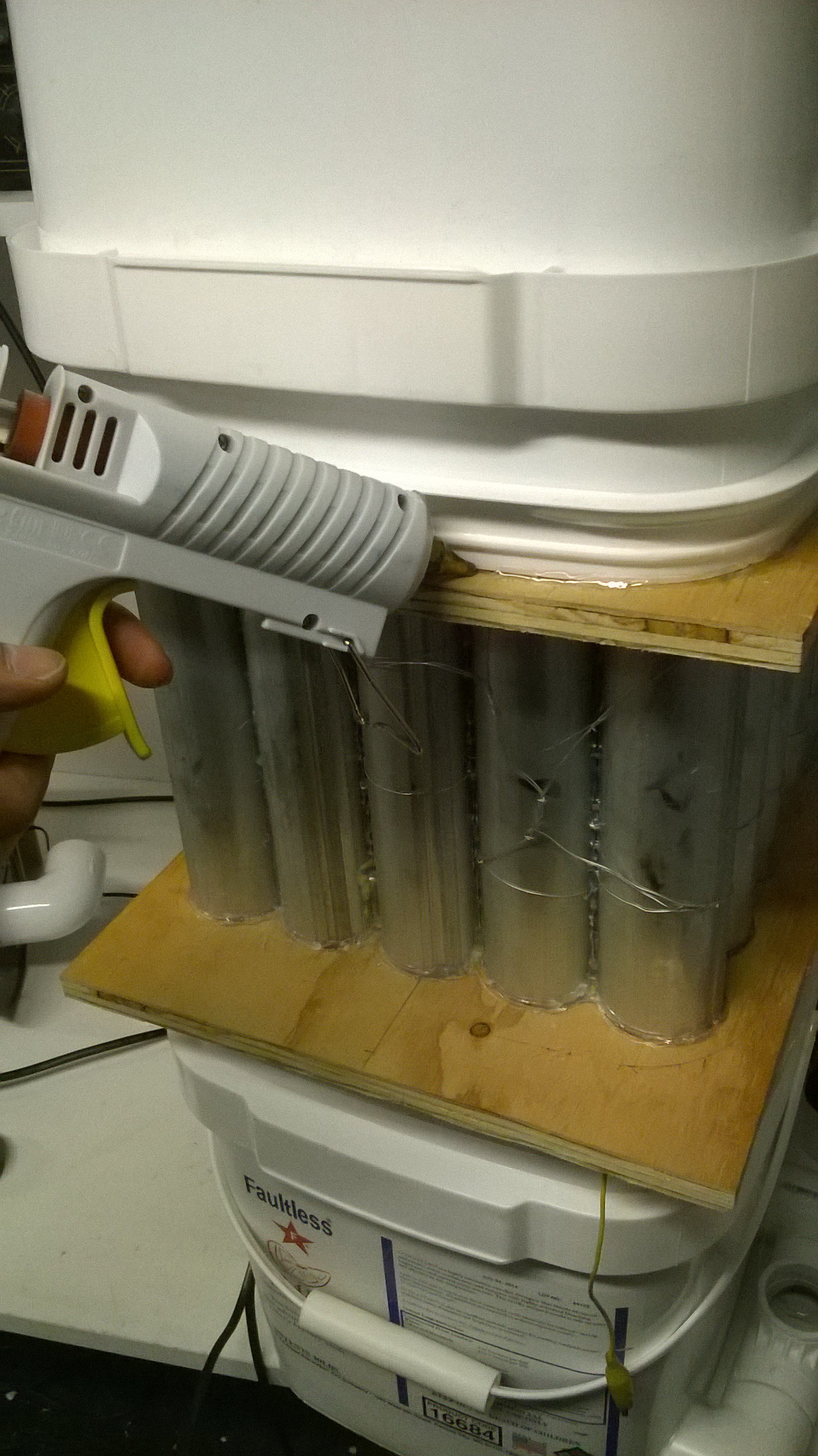
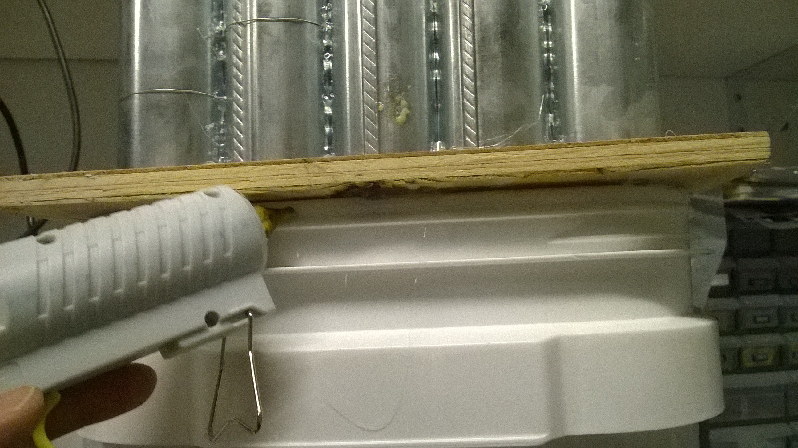
Now seal the buckets to the tubes using glue.
![]()
![]()
The tube electrostatic precipitator assembly is now finished!
-
33Step 33
The High Voltage Circuit
THIS CIRCUIT IS VERY DANGEROUS AND CAN MAIM OR KILL YOU. I'M NOT RESPONSIBLE IF YOU KILL OR HARM YOURSELF OR SOMEONE ELSE WITH THIS CIRCUIT. DON'T BUILD THIS IF YOU ARE NOT COMFORTABLE WORKING WITH HIGH VOLTAGE. BE EXTREMELY CAREFUL! CAPACITORS CAN MAINTAIN A DEADLY CHARGE AFTER THE POWER IS TURNED OFF. ALWAYS DISCHARGE CAPACITORS AFTER USE USING A LONG INSULATED STICK.
The high voltage circuit is what provides the power to the tube electrostatic precipitator. High voltage is needed in order for the wires in the tube to create corona and a strong electric field between the wire and the tube walls. As particulate laden air passes between the wire and tube walls, it will ionize and will be attracted to the walls via electrostatic attraction.
The circuit that provides the high voltage is a microwave oven transformer that feeds dual polarity 5-stage Cockcroft Walton multipiers. The voltage output between the positive and negative poles is about 25kV DC. The schematic that I follow is given here:
![]()
The only difference between the schematic and what I did is the number of capacitors and diodes used. I used 20 capacitors and diodes total. 10 diodes and 10 capacitors per pole. Note that two diodes and two capacitors make one stage. Just make sure that the left and right sides of your circuit matches that of the schematic.
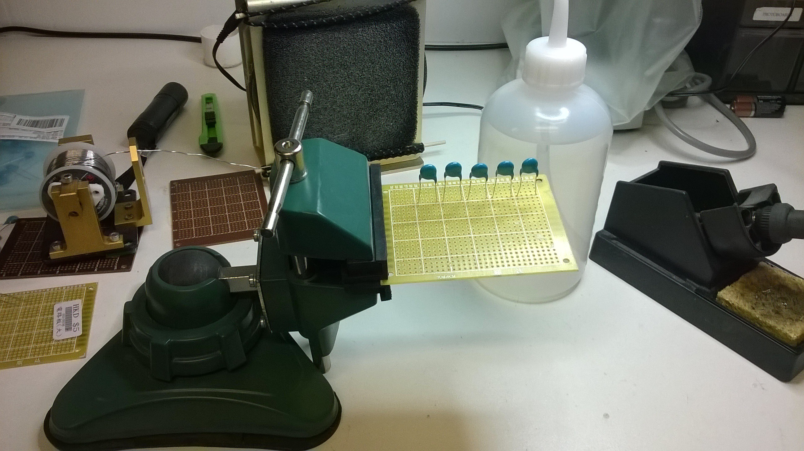
First take a perforated prototype board and solder 5 high voltage capacitors in a row. Make sure to evenly space them.
![]() Follow the schematic and solder 10 diodes in a zig zag pattern. Make sure the input and output diode matches the left and right sides of the schematic. Also make sure the diodes are facing the right way.
Follow the schematic and solder 10 diodes in a zig zag pattern. Make sure the input and output diode matches the left and right sides of the schematic. Also make sure the diodes are facing the right way.![]() Now solder the other 5 capacitors in a row on the other ends of the diodes.
Now solder the other 5 capacitors in a row on the other ends of the diodes.![]()
-
34Step 34
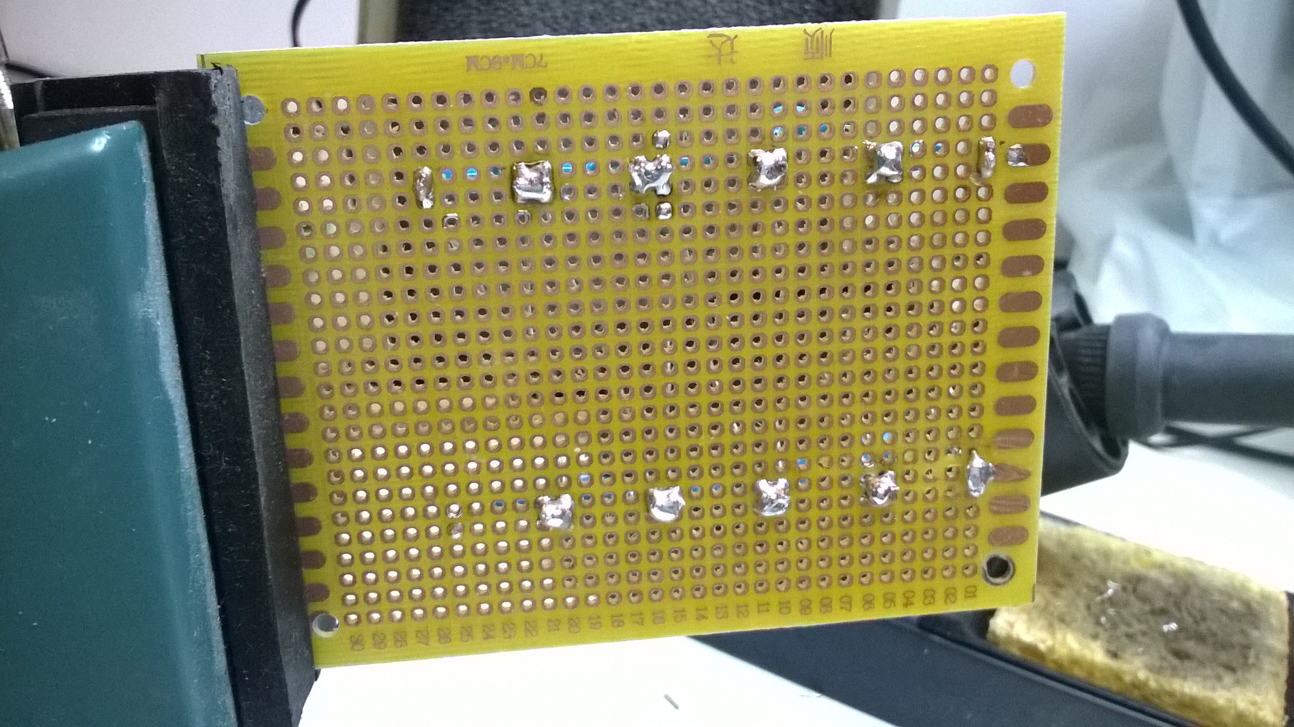
On the back trim all of the excess terminals
![]()
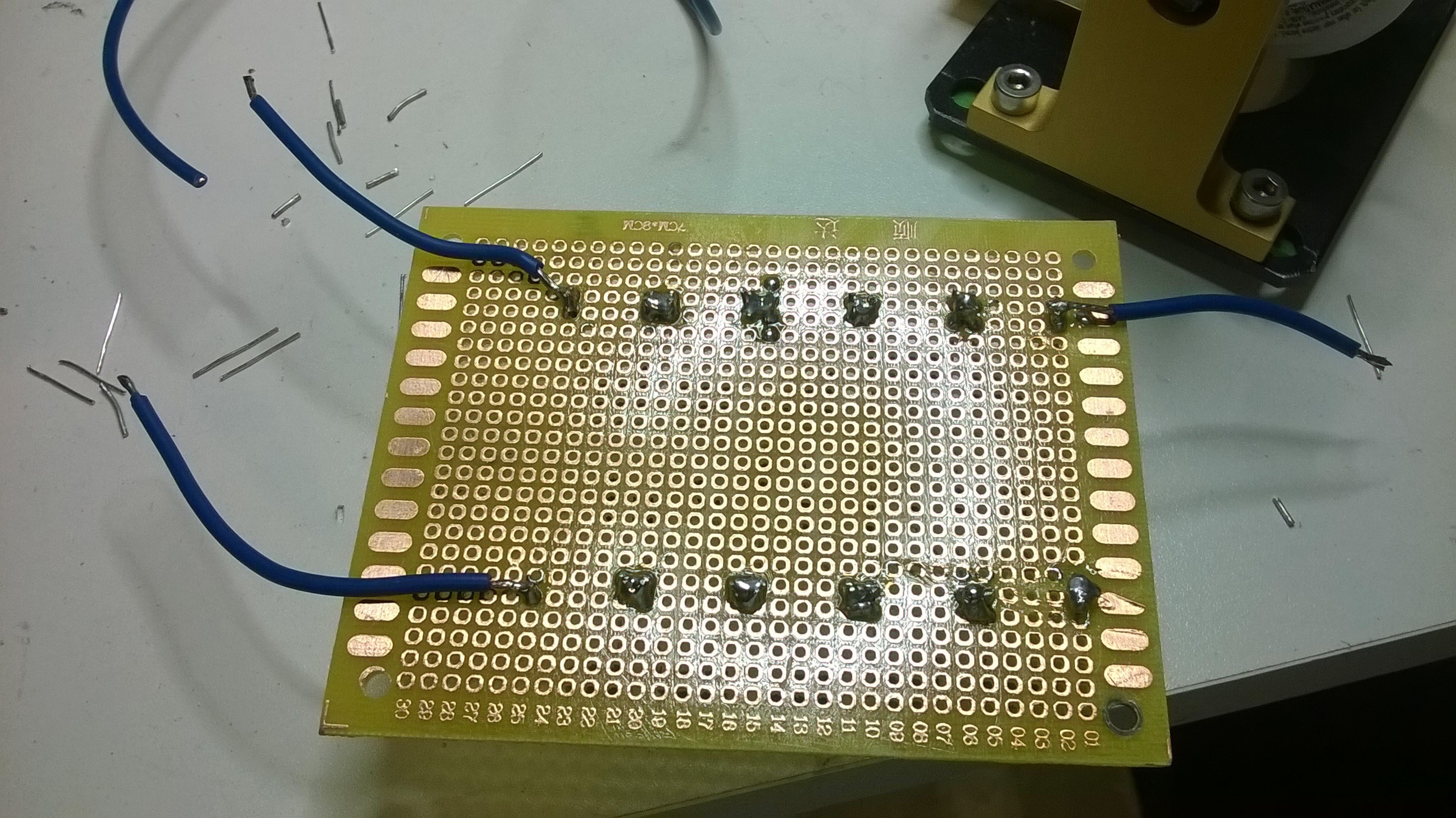
Then solder wires to ends for the AC input and DC outlet. Make sure it is soldered to the correct terminal as indicated by the schematic. It's a good idea to label the terminals with a marker.
![]()
-
35Step 35
Hot glue the soldered terminals on the bottom of the board to minimize arcing between them. You can also optionally submerge this entire circuit in mineral oil to prevent corona losses. I chose not to do this as I know it would end up a big oily mess.
![]() Now you will want to build another board like this but with the diodes facing the opposite direction to provide the opposite polarity.
Now you will want to build another board like this but with the diodes facing the opposite direction to provide the opposite polarity. Make a total of 4 of these board's as to have two pairs of the dual polarity multipliers.
![]()
This circuit can be connected in parallel and the outputs can be connected to each other to provide additional current at high voltages. You can either use two microwave oven transformer or a single microwave oven transformer and tie the inputs of all the multipliers together. I chose to use two transformers.
-
36Step 36
Now take a spare power cord and expose the two ends so it can be attached to the microwave oven transformer.
![]()
The AC input from the wall is the bottom two terminals of the transformer that is nearest to the thickest wire. The high voltage output is the single terminal that is in the center of the coil containing the thin wires. The ground terminal for the high voltage circuit is connected to the microwave oven's metal core.
![]()
-
37Step 37
Now wire the multipliers together according to the schematic.
![]() Mount the boards and the transformer to a piece of wood or something ridged and insulating. It may be wise to house the entire high voltage circuit inside an insulated box.
Mount the boards and the transformer to a piece of wood or something ridged and insulating. It may be wise to house the entire high voltage circuit inside an insulated box.![]() NOTE THAT THIS CIRCUIT MUST RUN FROM A BALLAST SOURCE OR FROM A DIMMER SWITCH OR ROUTER SPEED CONTROL! DO NOT PLUG IT DIRECTLY INTO THE WALL AS THE TRANSFORMER WILL OVERHEAT QUICKLY.
NOTE THAT THIS CIRCUIT MUST RUN FROM A BALLAST SOURCE OR FROM A DIMMER SWITCH OR ROUTER SPEED CONTROL! DO NOT PLUG IT DIRECTLY INTO THE WALL AS THE TRANSFORMER WILL OVERHEAT QUICKLY.The high voltage circuit is now finished.
-
38Step 38
DIY Modular Electrified Activated Carbon Pod Instructions
The activated carbon stage is what is mainly used to scrub out volatile organic compounds (VOC's) from the air. This stage also scrubs out any Ozone produced from the electrostatic precipitator stage. The activated carbon is electrified to provide additional collection surface from the previous electrostatic precipitation stage.
I created a very modular design using very cheap sandwich containers. By cutting a square hole in the lid and the bottom of the container and replacing the hole with aluminum screen material, it can hold 1-2 inches thick of loose activated carbon sold from an aquarium store or in bulk online for very nominal price. Air flow would pass through the container containing the activated carbon to scrub out VOC's. A number of containers can be stacked or placed side by side in parallel for larger volumes of air flow to match the needs of the application.
For activated carbon to efficiently scrub out VOC's, the velocity of the air flow must be slower than 0.5m/sec or as my cousin told me, 0.25 seconds or longer of contact time with the carbon. The volume of airflow will determine the amount of activated carbon used, its depth, and its cross sectional area of air flow. Using modular containers is very useful to customize the right amount of activated carbon for the right application.
![]()
Regular Activated Carbon Pod
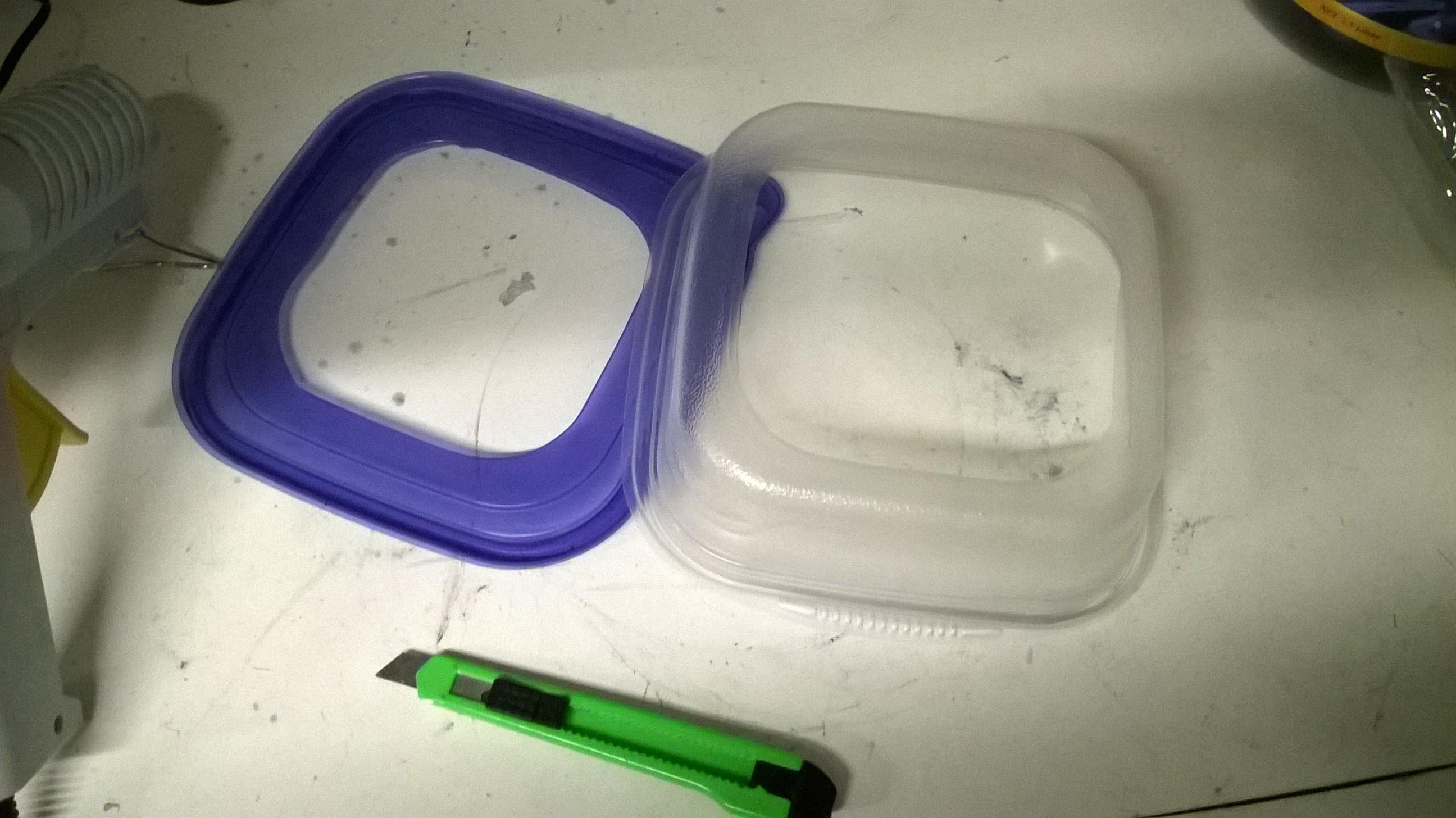
First begin by cutting a square hole in the bottom of the sandwich container as well as the lid.
![]()
![]() Do this for the number of containers that is needed for your design.
Do this for the number of containers that is needed for your design. -
39Step 39
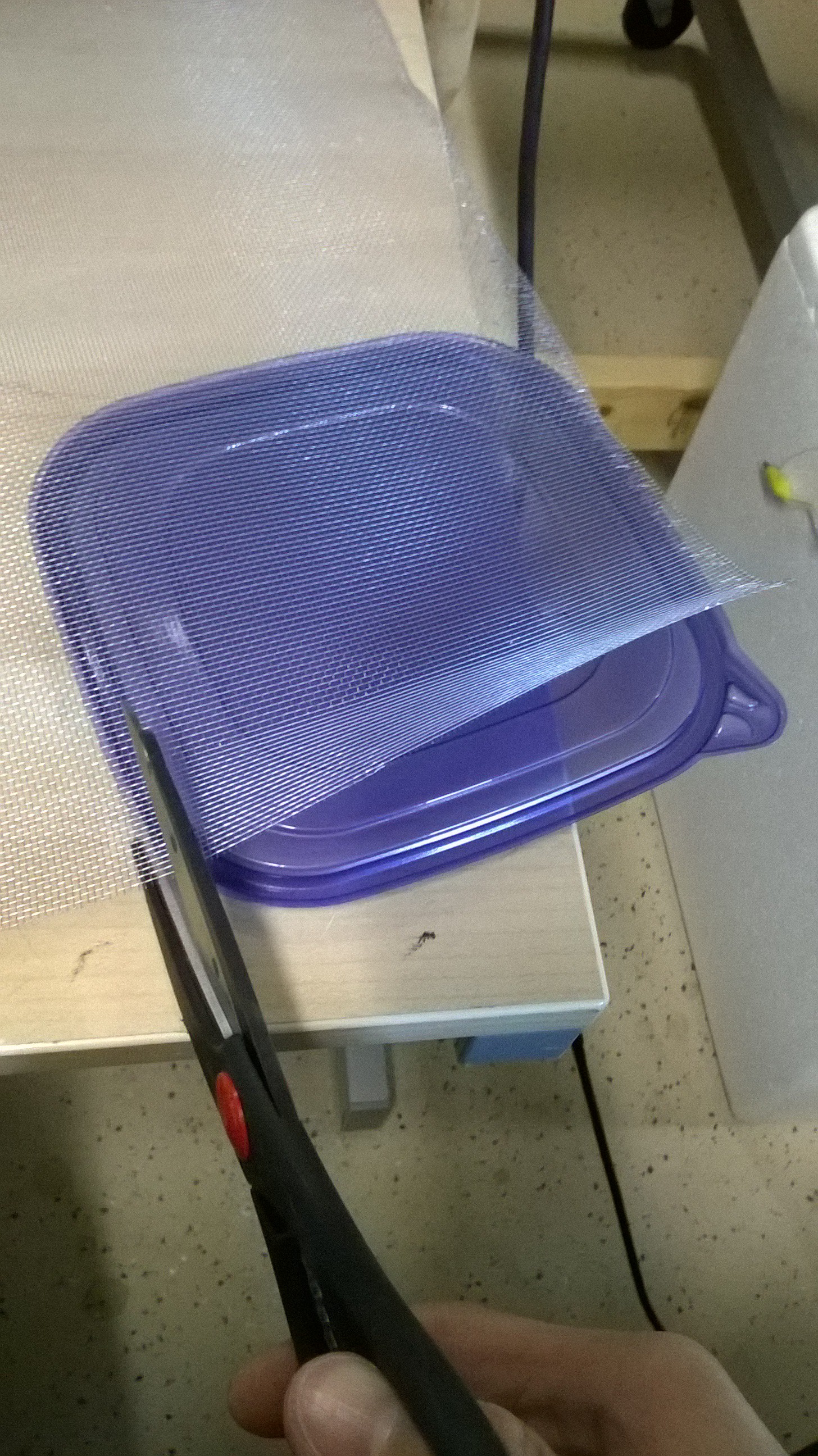
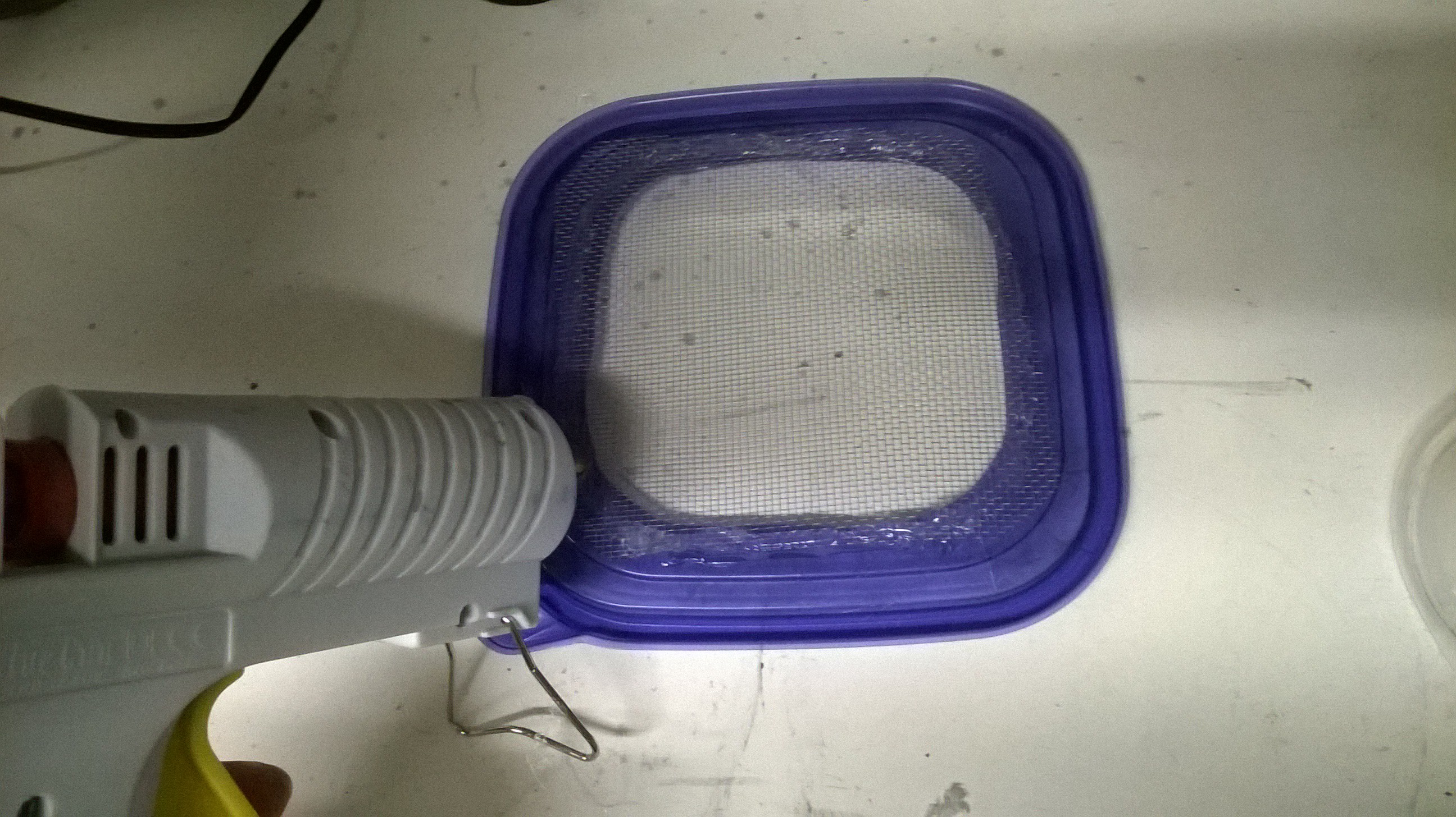
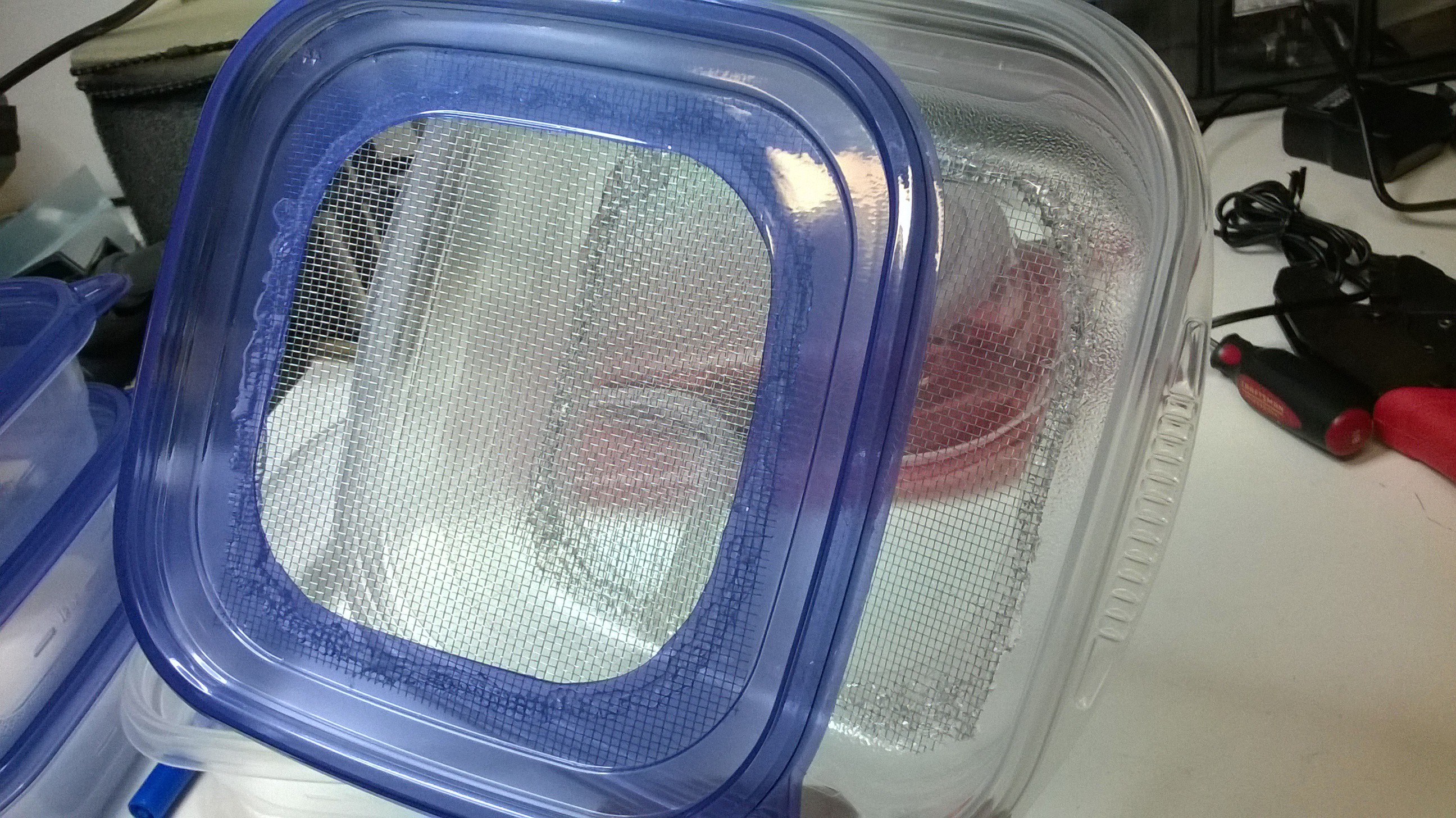
Cut out a square piece of aluminum screen mesh (the stuff used to repair screen doors and window screens) and glue a piece to the lid and another piece to the bottom of the container.
![]()
![]()
![]()
![]()
-
40Step 40
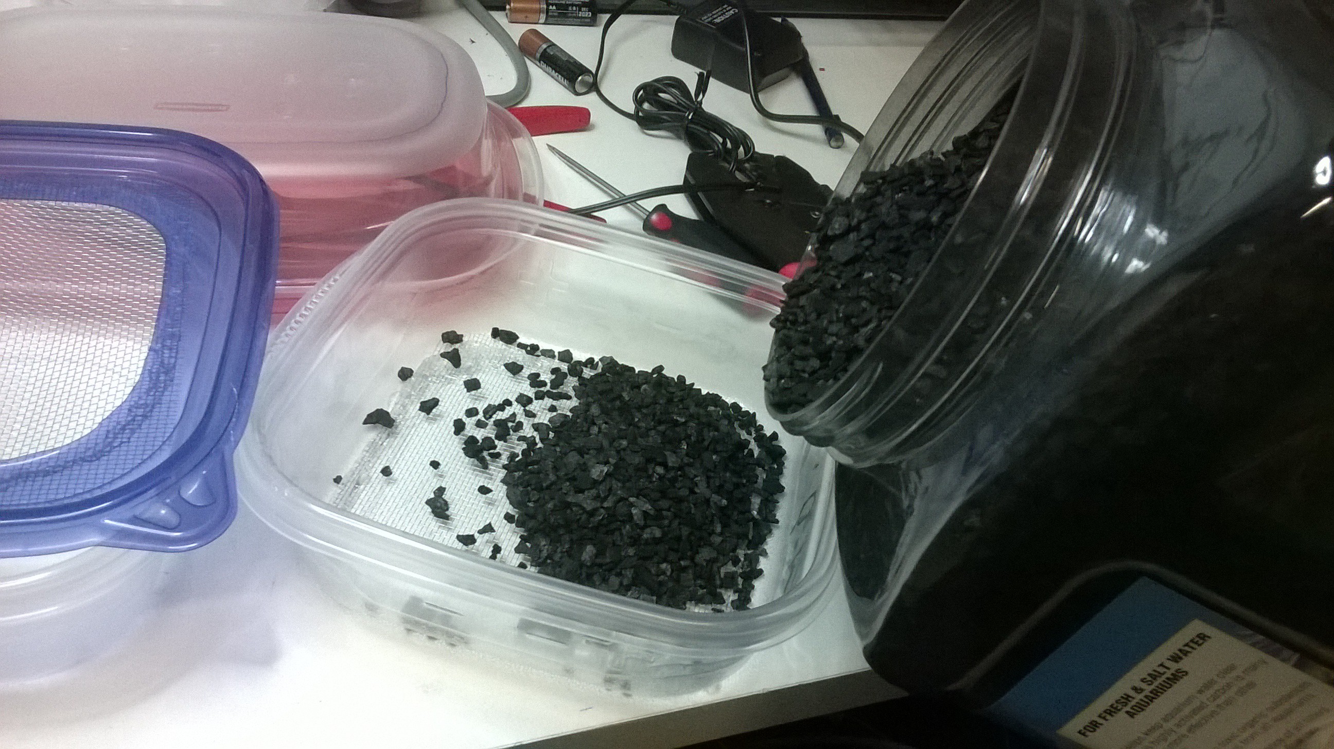
Now pour loose activated carbon into the container. You may want to rinse the carbon off first.
![]() Then place the lid on it. You now have an activated carbon pod!
Then place the lid on it. You now have an activated carbon pod!![]()
Household Electrically Enhanced Wet Scrubber
A household air purification unit for kitchens, labs, & smokers used to scrub fine particulates and VOC's out of the air.
 Then cut out the bottom of the square sandwich container and glue the container to the top of the lid. This will be used to interface the electrostatic precipitator to the activated carbon pods.
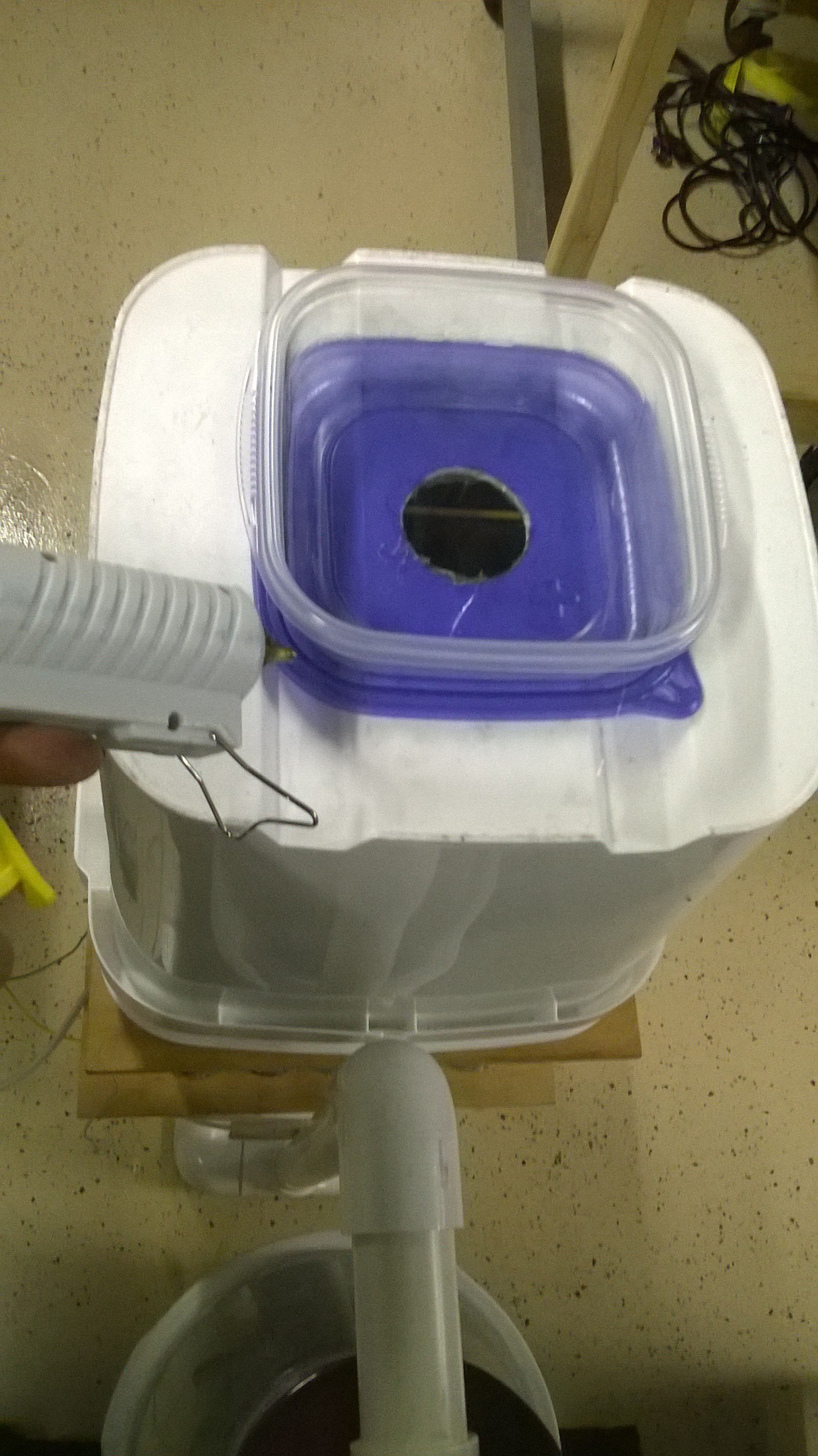

 Follow the schematic and solder 10 diodes in a zig zag pattern. Make sure the input and output diode matches the left and right sides of the schematic. Also make sure the diodes are facing the right way.
 Now solder the other 5 capacitors in a row on the other ends of the diodes.
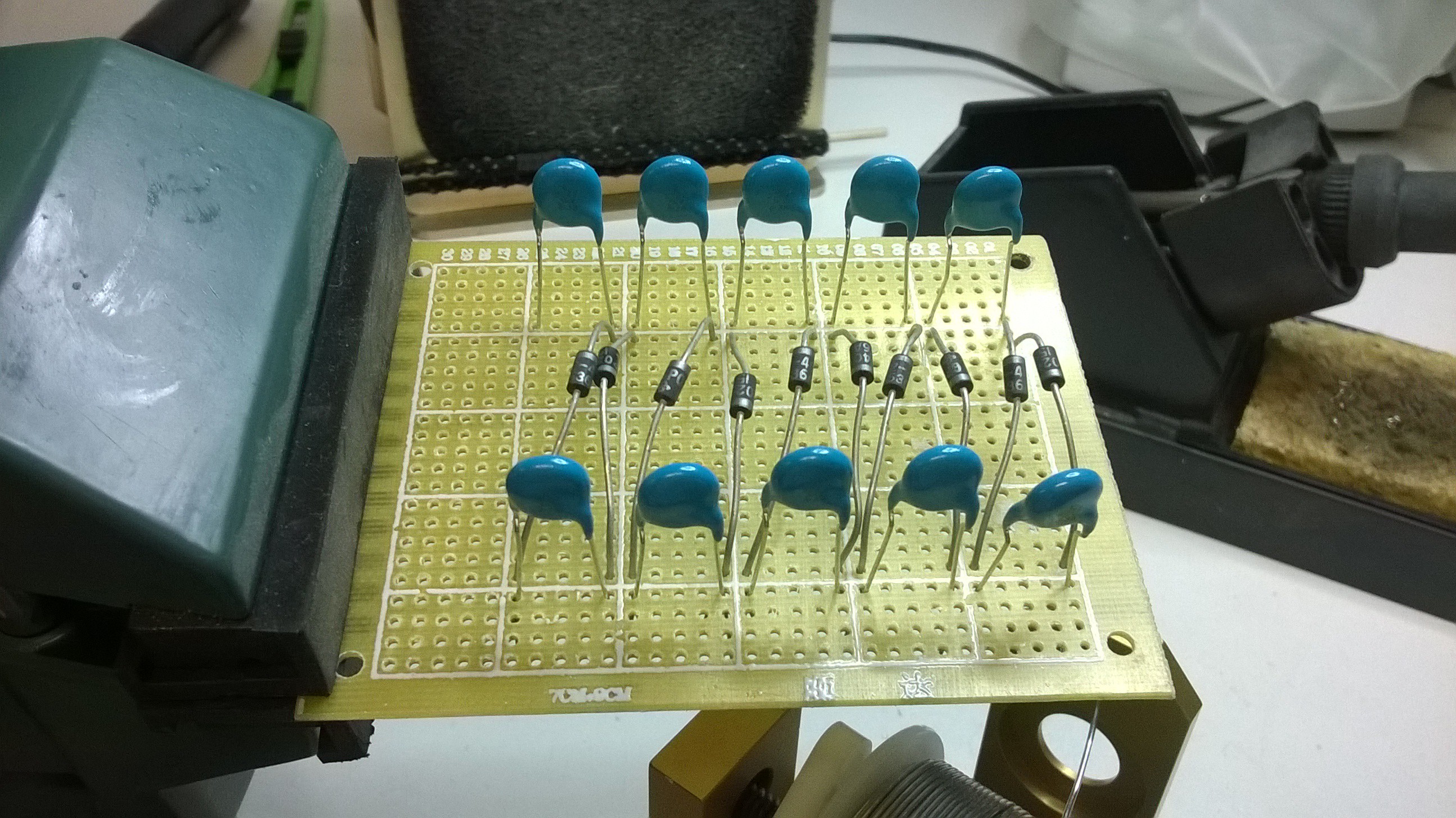
 Now you will want to build another board like this but with the diodes facing the opposite direction to provide the opposite polarity.

 Mount the boards and the transformer to a piece of wood or something ridged and insulating. It may be wise to house the entire high voltage circuit inside an insulated box.
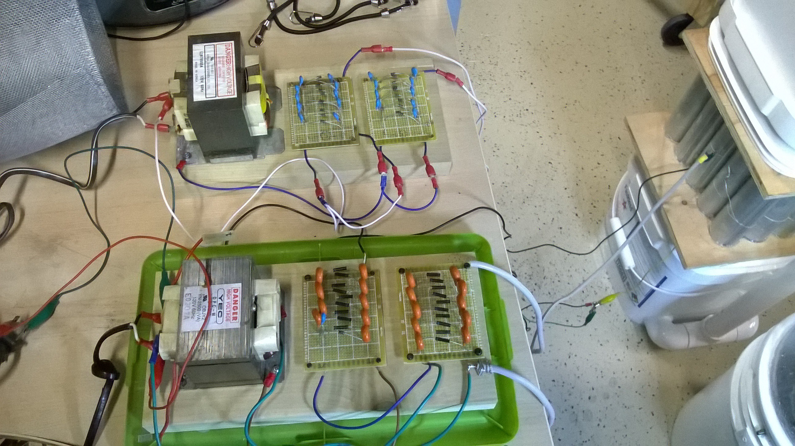 NOTE THAT THIS CIRCUIT MUST RUN FROM A BALLAST SOURCE OR FROM A DIMMER SWITCH OR ROUTER SPEED CONTROL! DO NOT PLUG IT DIRECTLY INTO THE WALL AS THE TRANSFORMER WILL OVERHEAT QUICKLY.
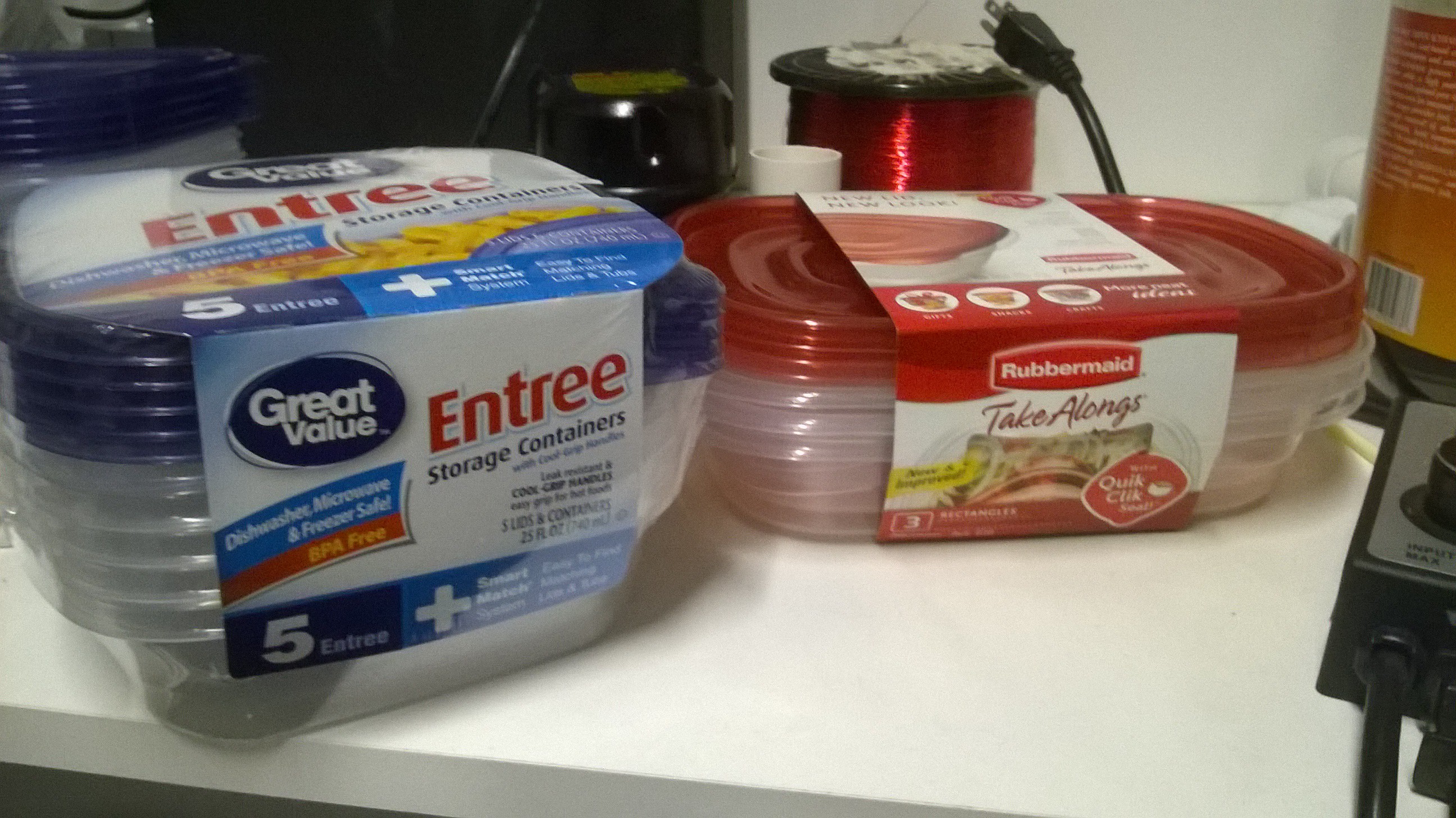

 Do this for the number of containers that is needed for your design.
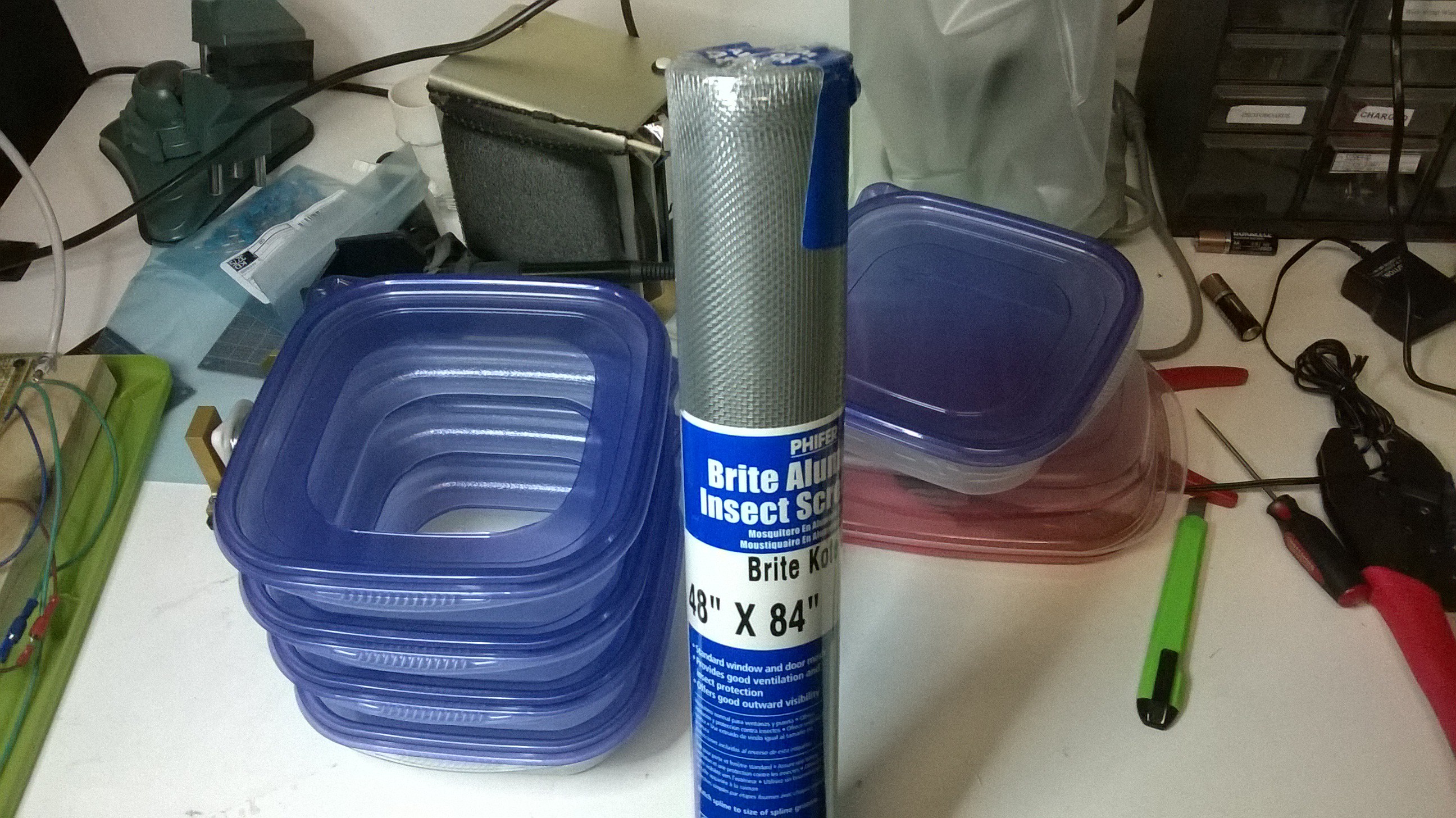
 Then place the lid on it. You now have an activated carbon pod!
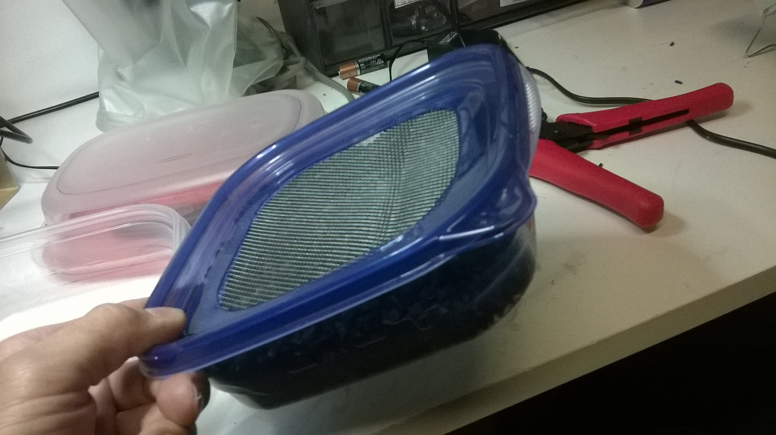
Discussions
Become a Hackaday.io Member
Create an account to leave a comment. Already have an account? Log In.