 x3n0x
x3n0x-
HC-SR04 Testing
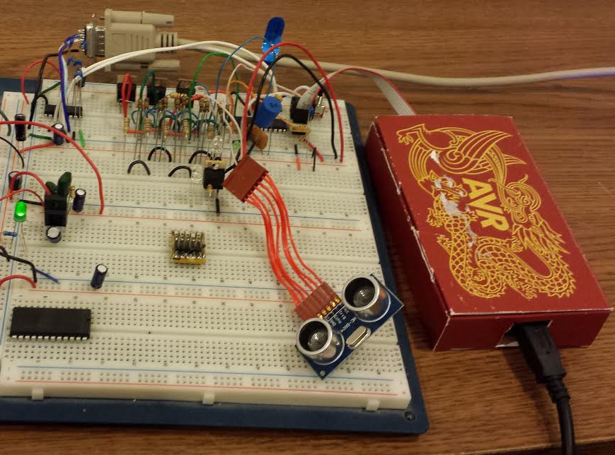
04/18/2014 at 01:43 • 0 commentsI already had on hand a few HC-SR04 ultrasonic range sensors that I purchased from Amazon for another project that got shelved. (These things are CHEAP!) Just to make sure the sensor would work as hoped I hooked it up on a breadboard. I don't currently have an actual Arduino or a clone, so I made do with an ATmega168A that I had on hand.
Ignore the extraneous components. They are leftovers from my last project and I was lazy and left them there since they didn't interfere with anything. The cable to the sensor obviously has too many wires, but I already had it on hand.
![]()
I compiled the example code for the NewPing library available at:
http://playground.arduino.cc/Code/NewPing
I first attempted to flash the Arduino bootloader to the chip and hooked the ATmega168 + MAX232 transceiver up to my USB to Serial Adapter. Unfortunately the Arduino IDE couldn't see it, so I gave up on the bootloader. I turned on the verbose compiler messages in the Arduino IDE so I could see where the hex file was being dumped. Once I located the hex file, I used Atmel Studio 6.1 and my AVRDragon to flash it with the test code. (I am much more familiar with Atmel Studio and avr-gcc then I am with the Arduino environment, though I'm by no means an expert.) Notice the ultra-fancy enclosure for the AVRDragon?
When I hooked the serial output to my PC it output only garbage when I set up Br@y++ Terminal for 115.2K baud. The example code was set to output at 115.2K, but I guessed that the clock may be at fault. I was running on the 8 MHz internal RC oscillator, instead of the 16 MHz external crystal that a normal Arduino would have. (I didn't have any 16 MHz crystals in my junk box.) I set the terminal baud rate to 57.6K and it worked!
-
Formatting Woes
04/17/2014 at 04:17 • 0 commentsStill learning how to use the editor. Bear with me. I will fix the formatting as I go! In any case it is not really that important right? The good stuff is still all there, a bit hard to read, but there...
-
The power supply Lives!
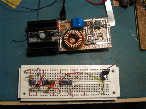
04/17/2014 at 04:00 • 0 commentsAfter testing, I have posted some pictures and a few steps to illustrate making the PSU. More is needed, but time is short. IN any case, here is a picture of the evil device next to it's bread-boarded pulse dividing circuit:
![]()
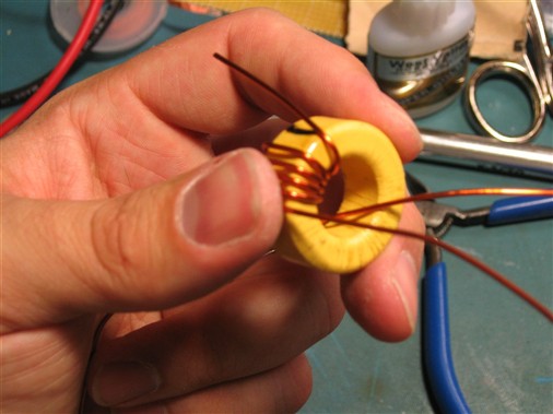
Now for some inductor winding Goodness:
![]() The inductor winding procedure will be covered in detail in the instructions... Stay tuned! Let the Fun begin!
The inductor winding procedure will be covered in detail in the instructions... Stay tuned! Let the Fun begin! -
It Begins...
04/16/2014 at 15:44 • 0 commentsAs of this post, the HV PSU has been built on its Protoboard and tested. It works very well as far as I can tell. I know because it bit me while I was testing it! Ouch! Pain! Post pictures here soon, as well as some of the schematics for this portion of the project.
 The inductor winding procedure will be covered in detail in the instructions... Stay tuned! Let the Fun begin!