Alex
Alex-
State of the Matrix
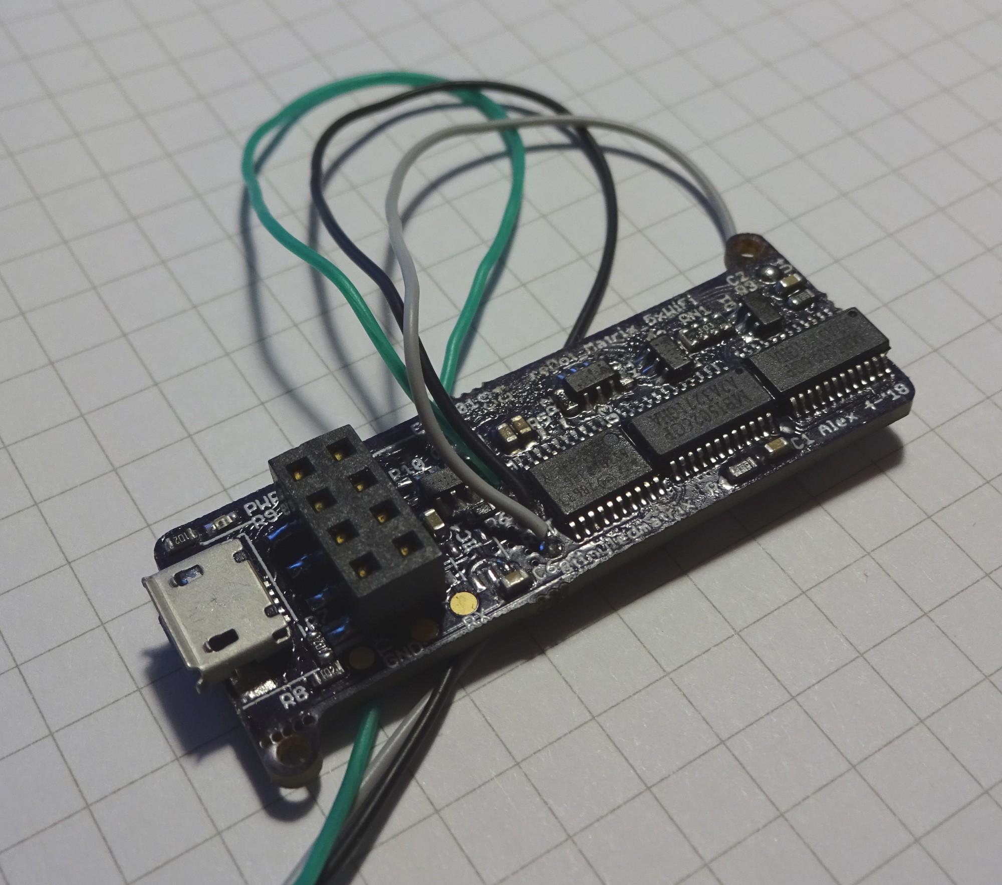
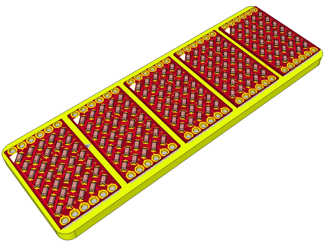
05/12/2018 at 23:21 • 0 commentsHere are some quick images of the current Hardware state: The Grind in the background is 5mm (~0.2'')
![]()
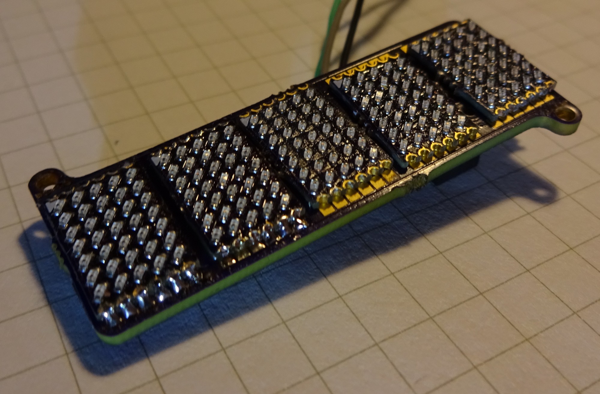
Two matrix-PCBs are soldered. They are also working, but I have no good images so far.
![]()
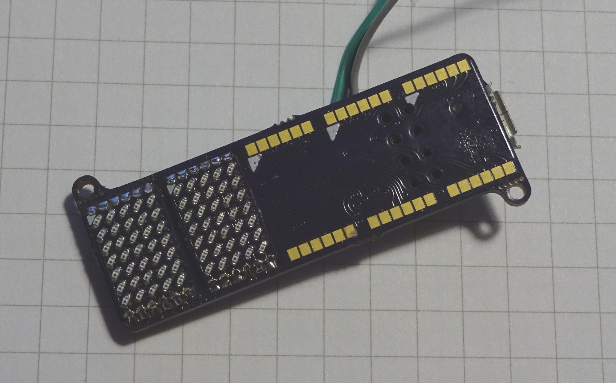
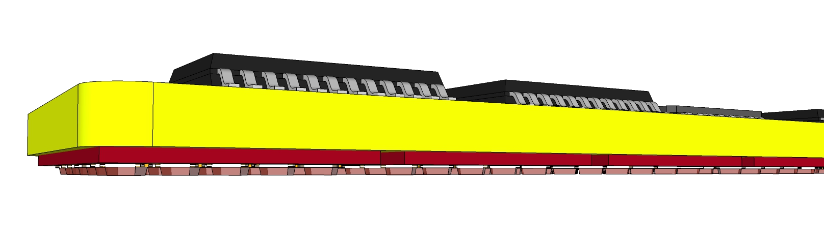
The back with the two LED driver ICs, a STM8s microcontroller, pinheader for ESP-01 and USB-connector for power
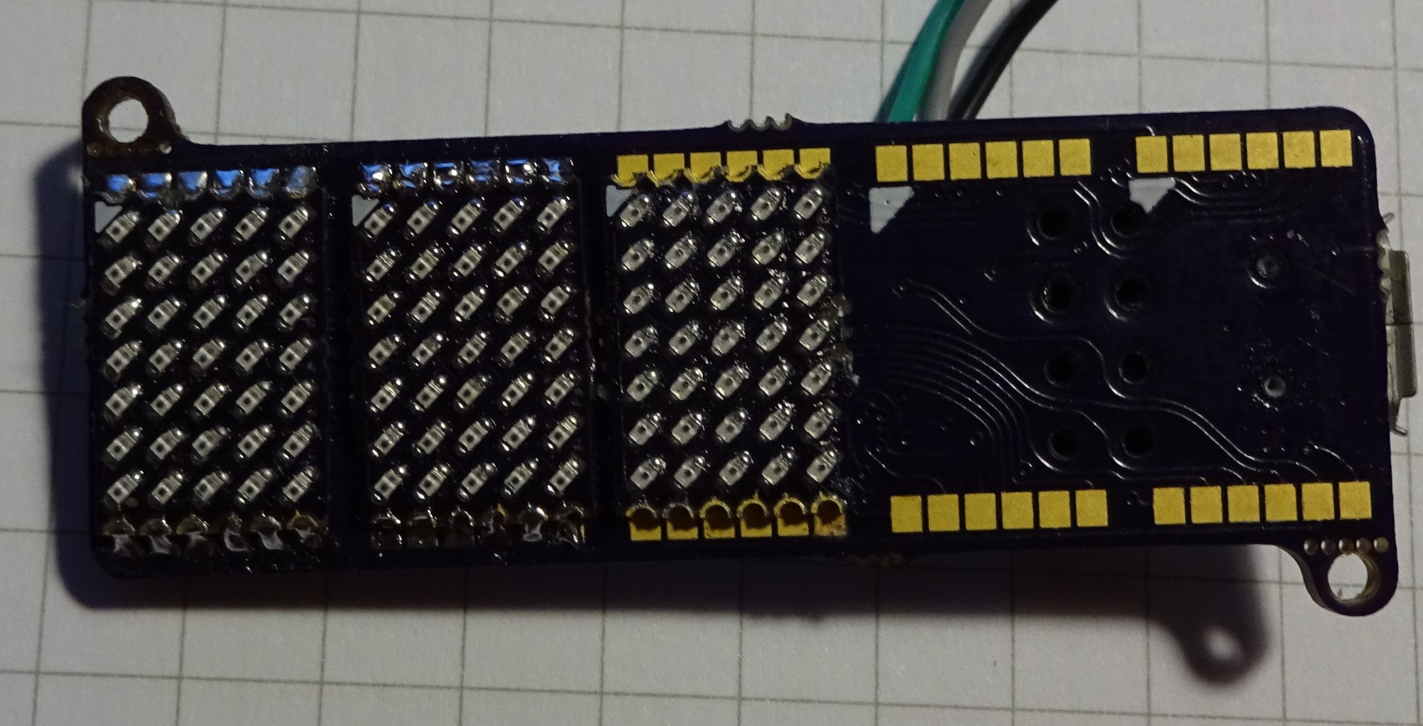
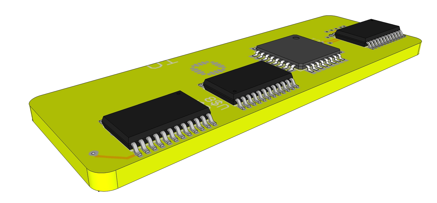
Can you spot the mistake on the next image?
![]()
Saw it? The LEDs on the third not soldered Matrix PCB are soldered 180° rotated. This does not work with the main PCB. But sadly the cathode marking on the matrix PCBs is wrong. And I soldered the first five matrix PCBs wrong for the main PCB. With five not usable matrix PCBs I run out of LEDs sadly :(
![]()
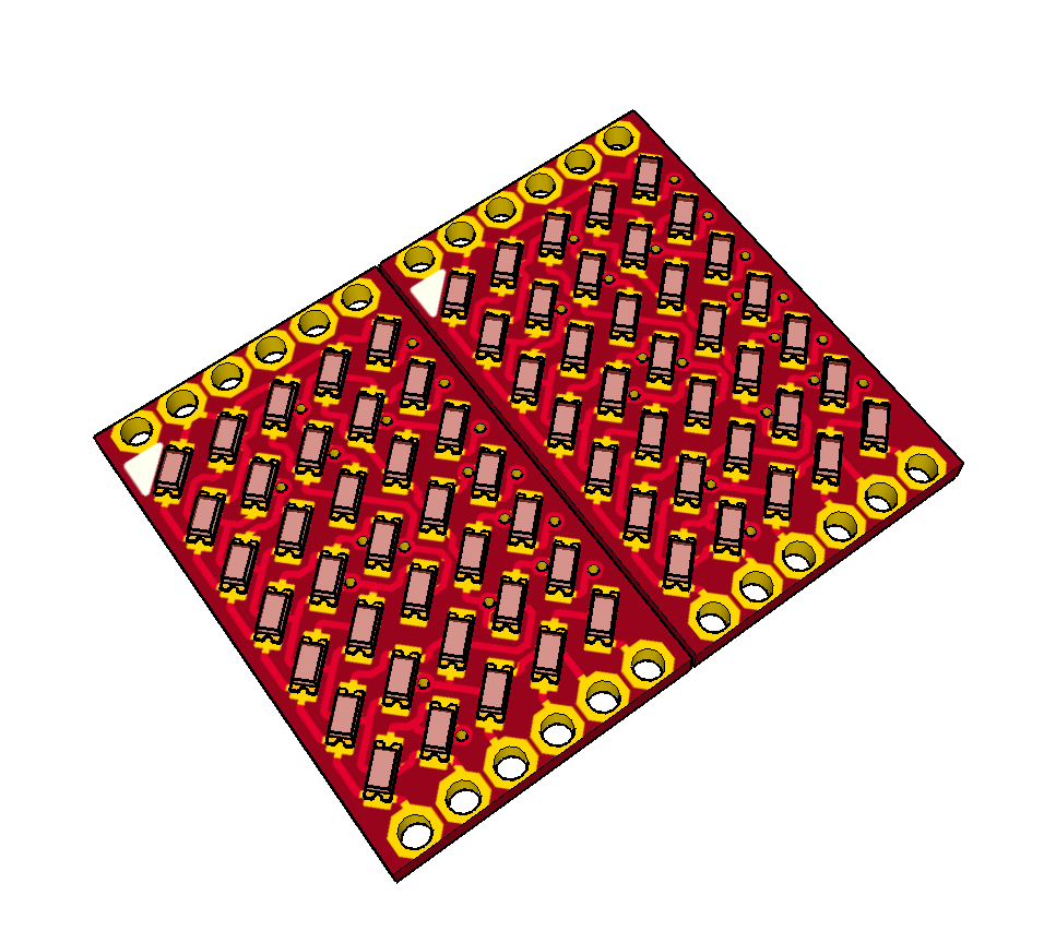
Like this it should look at the end.
Now I will work on the STM8 firmware. So far only switching all LEDs on is working.
-
First matrix PCBs soldered
04/12/2018 at 21:46 • 0 commentsIf you follow me on twitter (@tinyledmatrix) you could already know these pictures. I soldered the first five matrix PCBs. At least a quick diode test with the multimeter was positive. PCBs for the main PCB should arrive tomorrow, if the tracking is correct. So more soldering work to do on the weekend!
![]()
![]()
-
Update
04/05/2018 at 20:04 • 0 commentsSome short updates:
1. The Matrix PCBs arrived. I will post some Images here, when I soldered one.
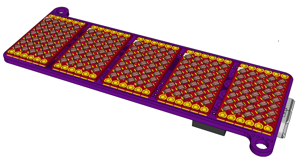
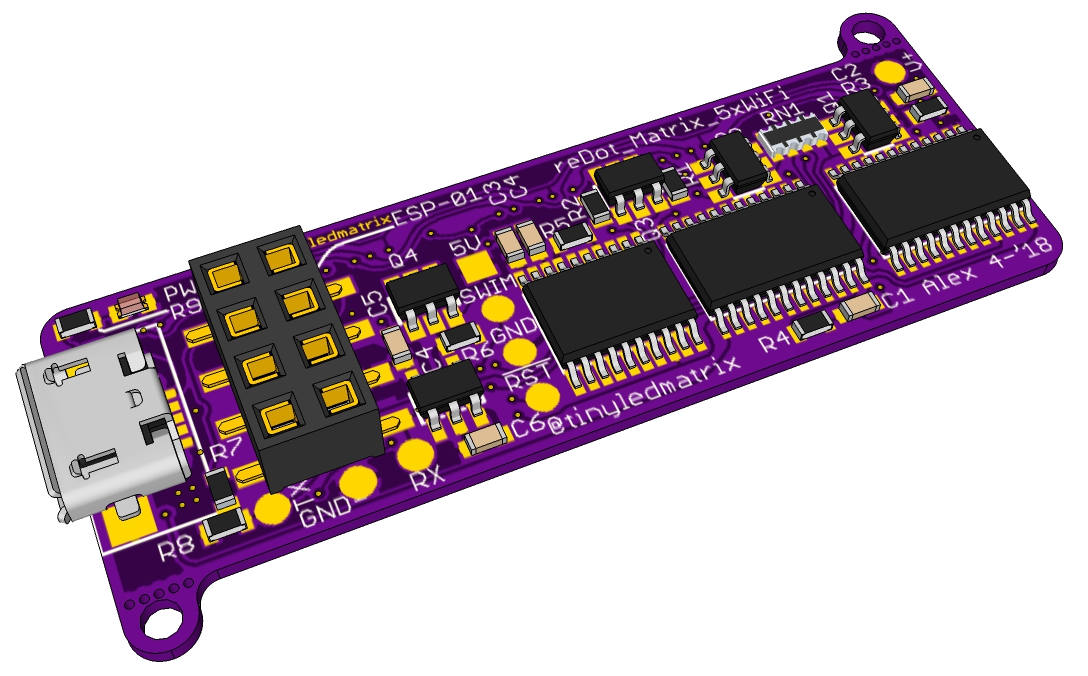
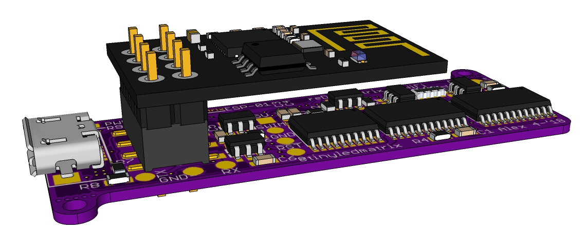
2.The Layout for the Main PCB is ready! I ended with a pin header to use ESP-01 Modules for the connectivity. Here some nice renderings:
The front LED side with five LED PCBs. Here in red
![]()
The Pack with all the LED control Stuff, an STM8 Microcontroller and a pin header to add wifi with an ESP-01:
![]()
Like This it should look with an ESP-01:
![]()
-
Placement Tests
03/21/2018 at 22:10 • 0 commentsSome First Tests:
- The main board is sadly to small to fit an ESP-Module, so for Wifi I must got to ESP8285
- There is enough place for all needed ICs, passives should also fit
![]()
![]()
![]()
I will continue with routing (probably during may 6 hour train trip on Saturday)
-
Number of Digits, Drivers, Microcontroller and Interface
03/20/2018 at 21:29 • 0 commentsI did some brainstorming about Number of Digits, Drivers, Microcontroller and Interface. I ended up with the following for the the first main board design:
- 5 Digits wich are connected as 25x7 Matrix (25 cathode columns and 7 anode rows)
- Driven by:
- two 16-Bit constant current low side drivers (MBI5026 or similar)
- one 8-Bit source Driver (probably MIC5891) in the same SPI bus
- OR one logic demux with p-fets or driver directly controlled by GPIOs
- One low cost 8-Bit MCU (probably some SMT8S)
- doing all the LED multiplexing
- UART and/or I"C as control Interface
- ESP8266 Module
- because everything needs wifi
- Maybe ESP8285 to safe some space
I hop all these ICs will fit on the back of 5 Digits. I will try this the next days.
-
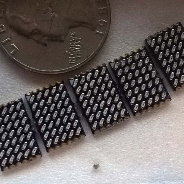
Matrix PCB layouted
03/15/2018 at 18:05 • 0 commentsFor this project I will use Matrix-PCBs. These Matrix PCBs will get soldered on the main PCB. Main features are:
- 5x7 0402 LED Matrix
- no components on the back
- castellated holes (50mil /1.27mm pitch) on the sides to connect to main PCB
I also orderd some PCBs at OSH-Park to test this. The LED Matrix itself is the same as the latest Version of #reDOT_smart but this project will see no update.
The rendering (made with eagleUp and SketchUp) show two of the Matrix PCBs side be side, as they will get mounted on the Main PCB (castellated holes not shown right) .
![]()
Further on I will design the Main PCB but I did not decided many things there. For example one main/important decision would be the microcontroller. My favorites so far would be
- ESP8285 - to get wifi
- Atmega328P - the classic one
- SAMD09/11/21 - modern Arm core, but maybe little bit overkill
- PIC16/18 with USB - it looks like implementing USB on PIC is easier then on SAMD11/21
Do you have any thoughts about this selection or do you have an Idea for an additional microcontroller to consider? Than please leave a comment!
Based on microcontroller Selection I will chose additional components like Shift registers to expand IOs, led driver, clock stuff, power connector, interface connector an so on.
reDOT_Matrix
A alternative approach to create a multi digit 5x7 LED Matrix Display