Mini rpi2 laptop
Small form factor laptop in the style of old HPC's like the Jornada.
Small form factor laptop in the style of old HPC's like the Jornada.
To make the experience fit your profile, pick a username and tell us what interests you.
We found and based on your interests.
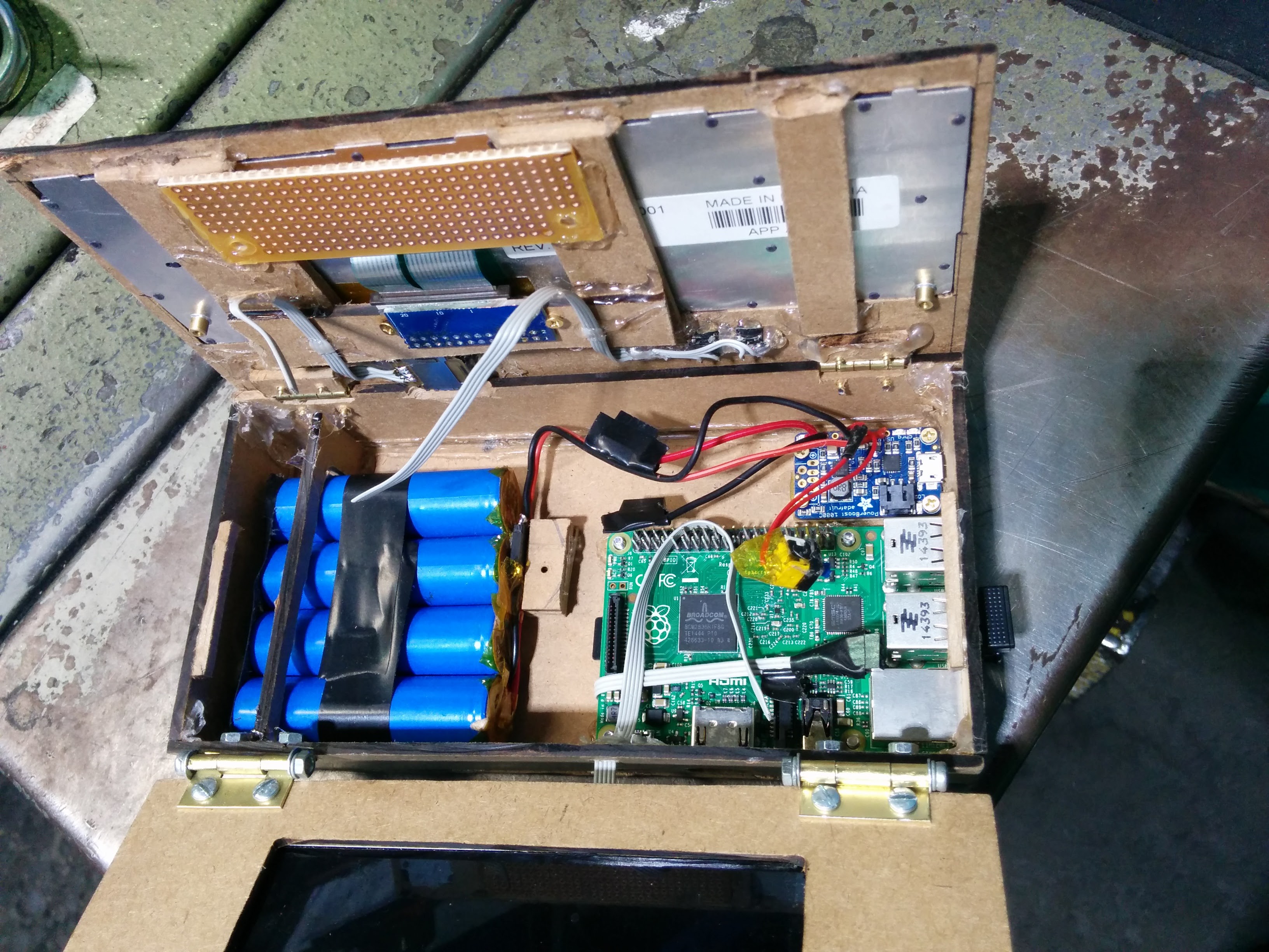
I haven't updated this project in a couple months, but I have been working on it on my spare time. I dropped it one day and I figured it was time for a rebuild anyway. I was having trouble finding the time to work on getting the teensy programmed so I shelved that part for now and found a different keyboard that was USB interface. I ordered this one on eBay. It's a generic case for a tablet with a keyboard. I used a razor and cut the case up and removed the keyboard from it. Then i designed a new housing out of my favorite material, dollar store clipboards made from mdf. This version is slightly bigger since the keyboard is larger then the last one but that gave me more room inside so i added 2 more 18650 cells. I also salvaged some speakers from and old laptop and wired them to the amp in the lid.
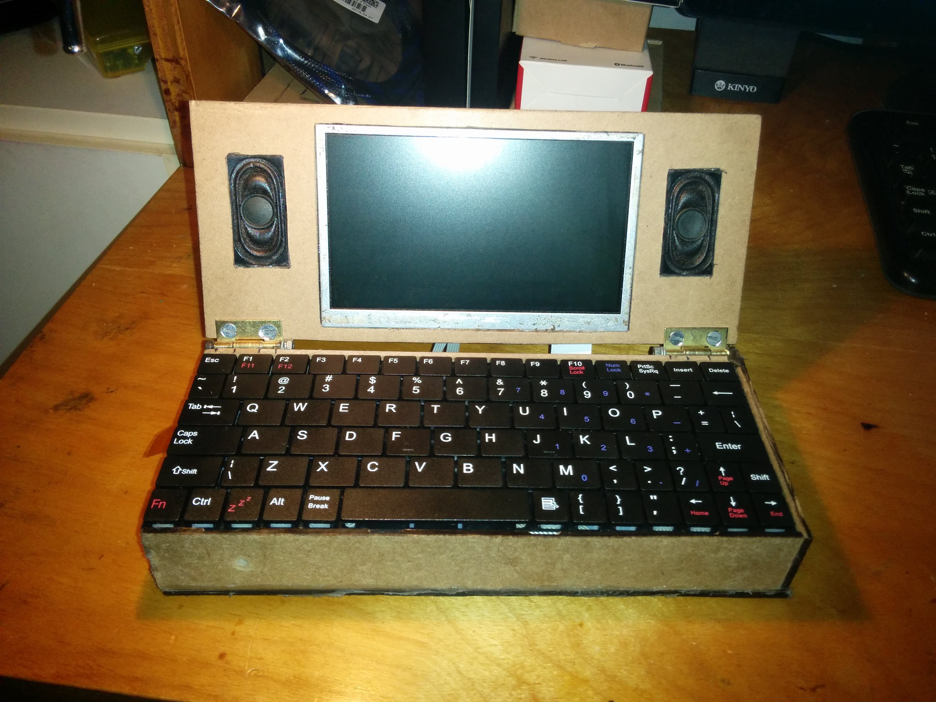
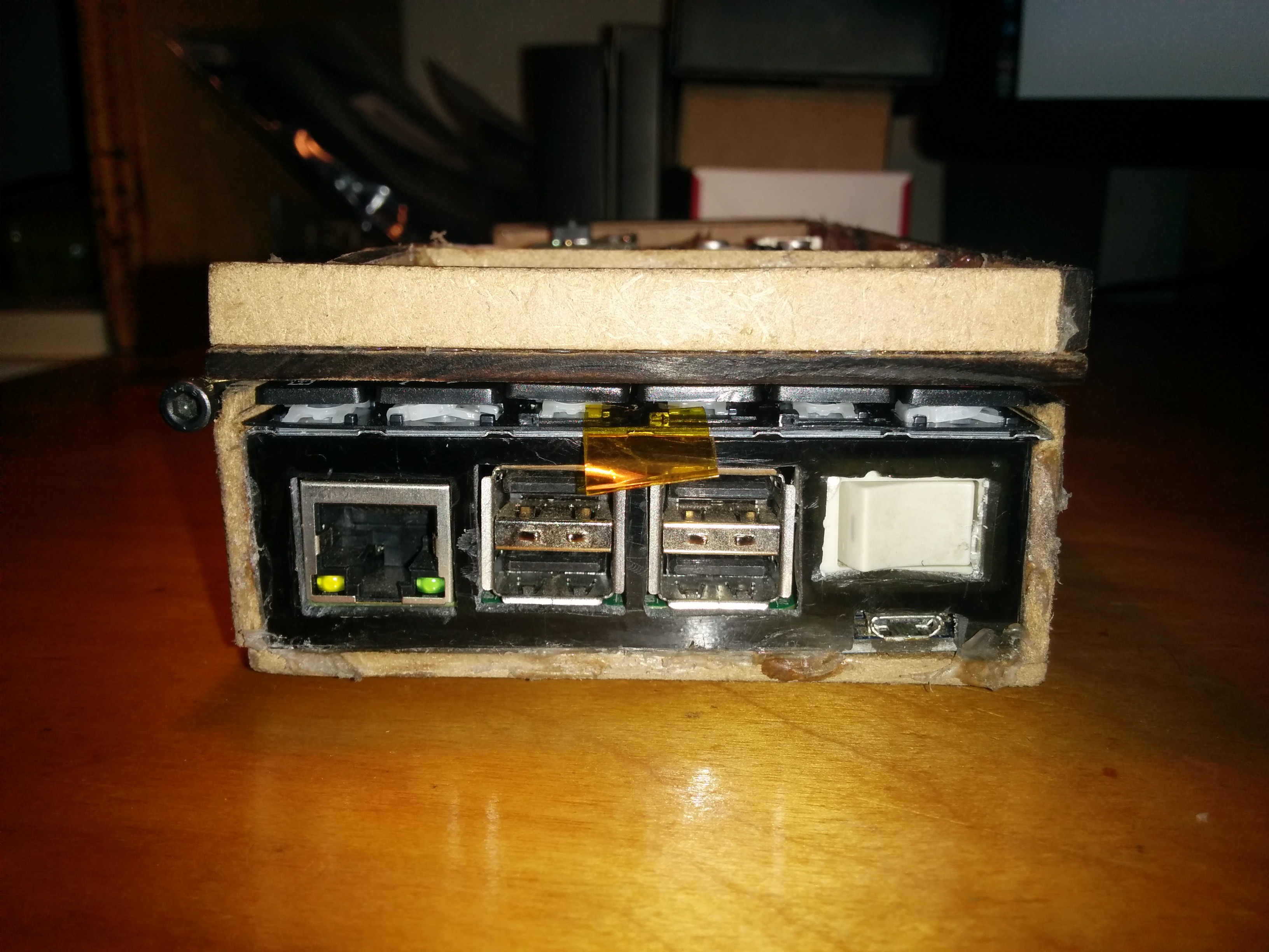
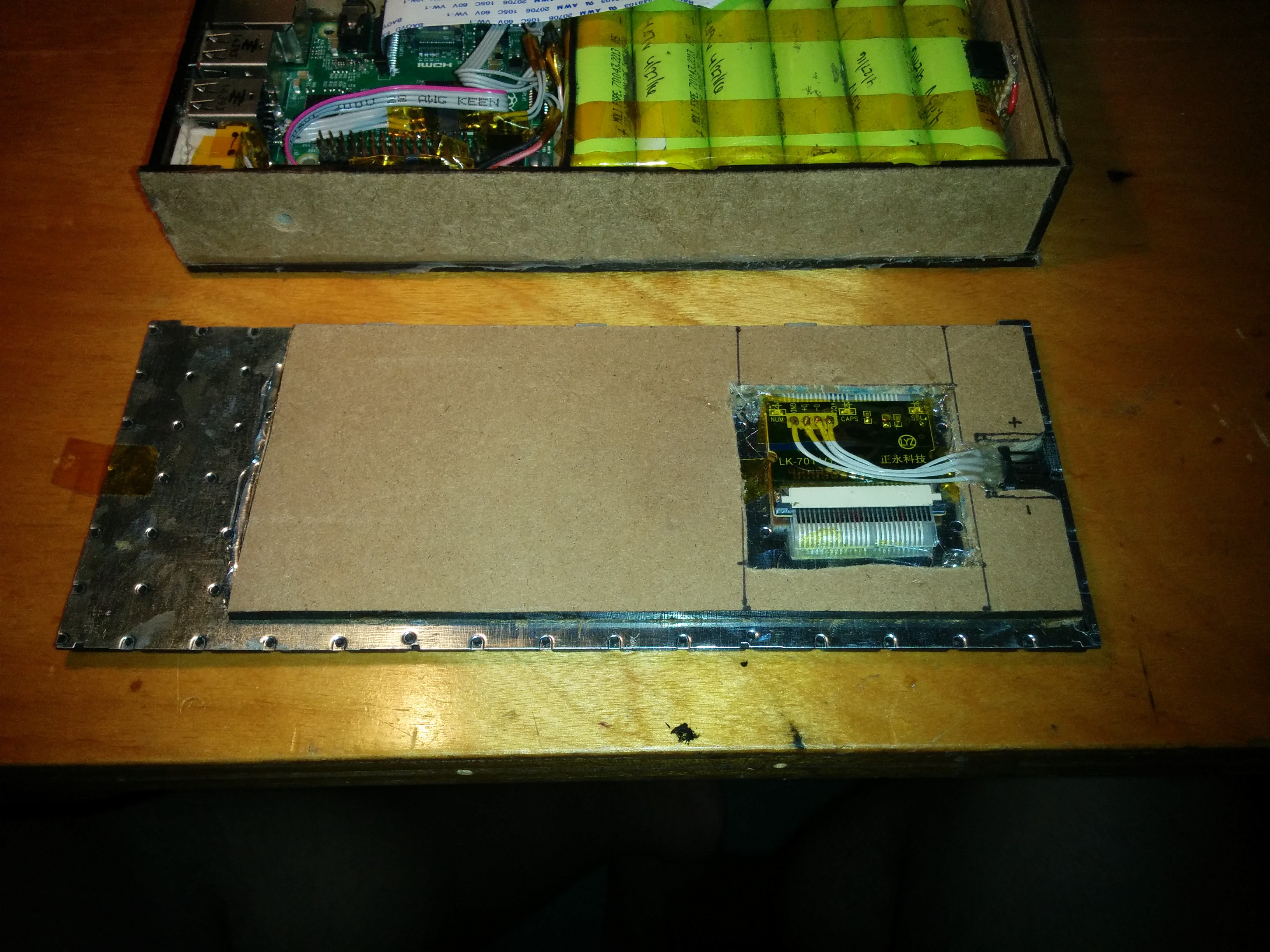

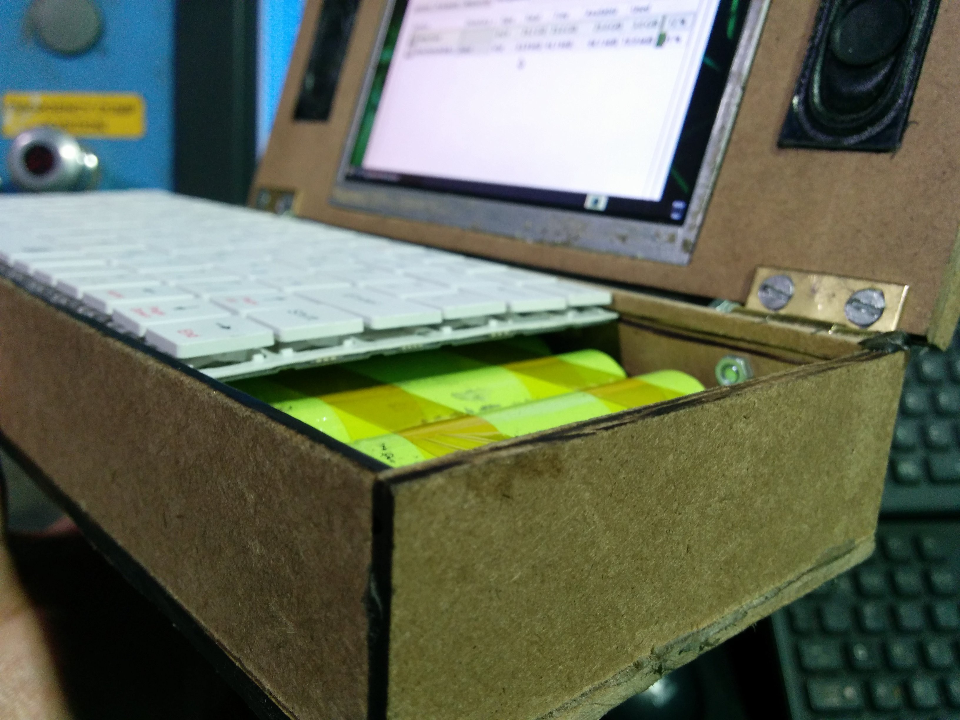
The day the Pi3 came out i ordered one and tried it inside my project. The performance was very good and built in Bluetooth and WiFi was nice, but man is the Pi3 a hungry little board. It also runs hot. I was having trouble supplying enough power to it so i went back to using the Pi2 until i can sort the power issues.
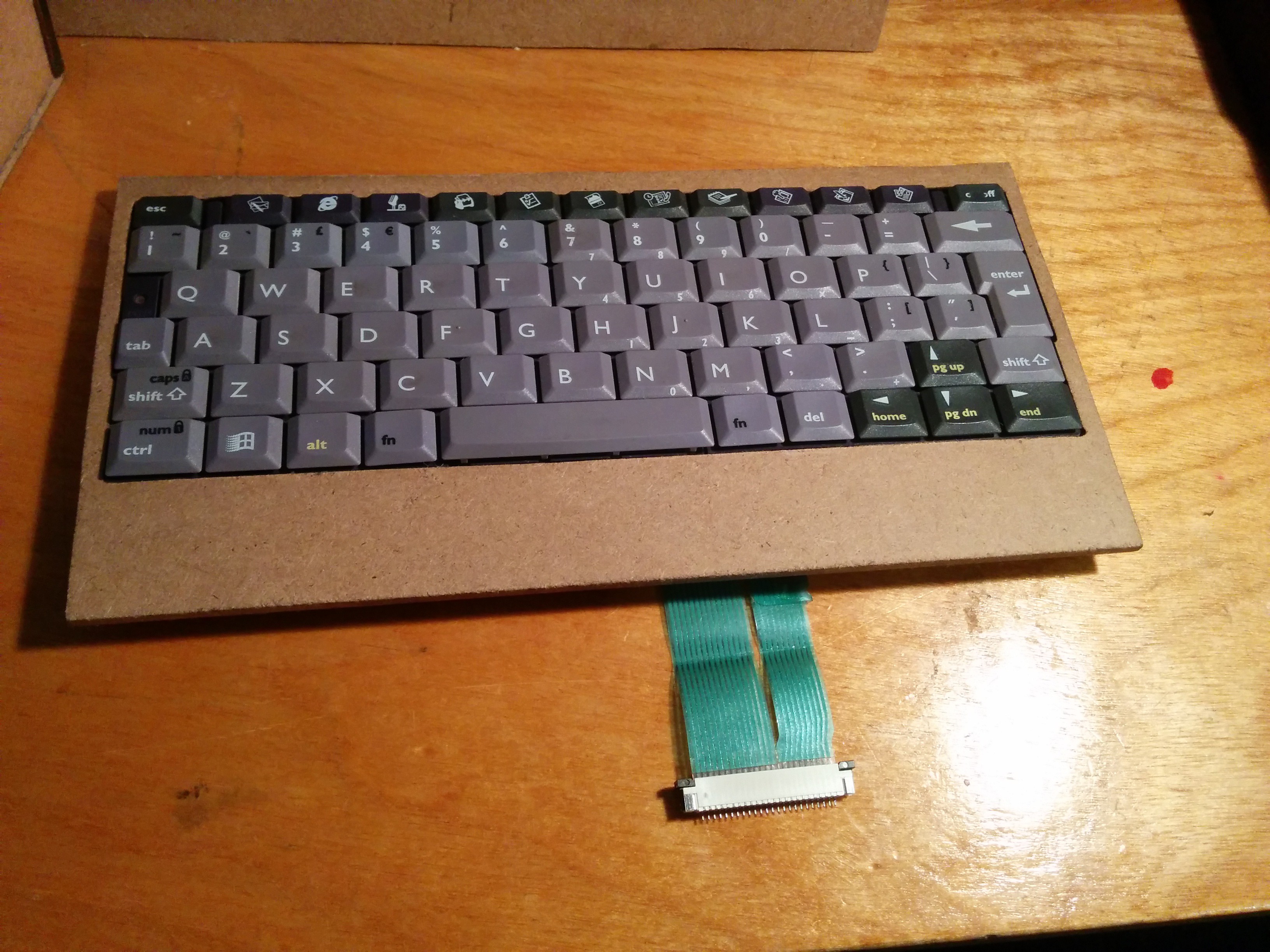
While remaking the housing I got an idea for the keyboard to slide into it so I carefully cut some grooves along the top. It worked better than i thought it would. I also wanted to eliminate the loose wires running to it so i came up with another idea to use male and female pin headers. I glued a piece of MDF to the bottom of the keyboard with some space cutout for the small board and a space cut out for the male pinheaders. I hot glued them in place then carefully lined up the female header on top of the batteries and glued it in place. So now when i slide the keyboard in place the pin headers connect. Then i wired this to one of the pi's usb ports by removing the metal shield from the back and cutting the traces to the upper usb port which is non-functional now. I might wire in a hub and connect this port back into the hub to make it functional again.
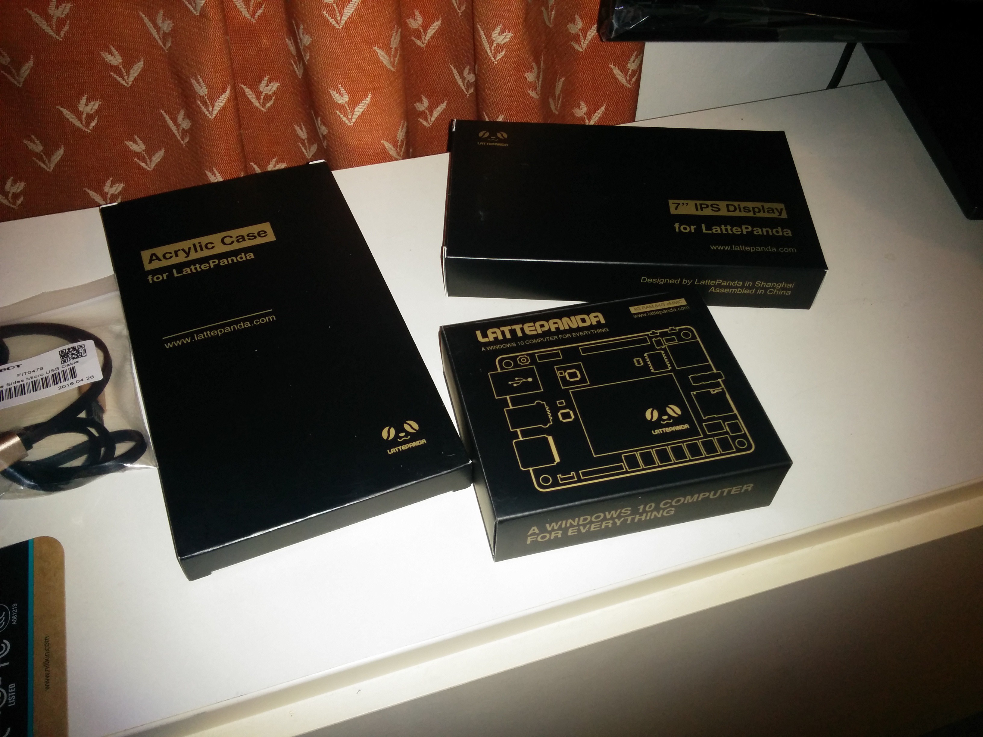
I'm currently awaiting some boost converters i ordered. I want to try using two of them wired to the same battery. One for the pi and the other for the screen and audio amp. It'll probably be a couple weeks until they arrive. I use a Bluetooth mouse now since i couldn't find a good place for the psp joystick. I just received my Latte Panda with 7 inch screen and I'm thinking about making it portable too.
I had trouble with the keyboard code so I went back to working on the mouse part. I got it working almost the way I want it with help from someone on reddit. The mouse works after playing around with the sensitivity value in the code. At first the pointer moved really slow. I lowered the value to around 25 and it moves fast enough but now the pointer wanders a little. The left and right click buttons are working.
So back to the keyboard, I have worked out the pin mapping for the keyboard to teensy connections and I did some work on the matrix and the different states (shift, fn..) for the button presses. These are the pin mappings
columns: keyboard pin   |   teensy pin (with arduino pin numbers)
                     1  |  27
                     2  |  0
                     3  |  1
                     4  |  2
                     5  |  3
                     6  |  4
                     7  |  5
                     8  |  7
                     9  |  8
                    10  |  9
                    11  |  10
                    12  |  11
                    13  |  12
                    14  |  13

rows:    keyboard pin   |   teensy pin
                     A  |  22
                     B  |  21
                     C  |  20
                     D  |  19
                     E  |  18
                     F  |  38
                     G  |  39
                     H  |  40
                     I  |  41
Hopefully that makes sense. And here is the matrix. I don't know how to paste it without it getting all jumbled so I'll post a screenshot.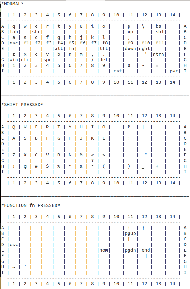
I will continue to work on this and hopefully learn how to get it working.
I managed to get the teensy working. For some reason my windows laptop wouldn't see it anymore so i tried my main Ubuntu pc with arduino ide. At first it wouldn't work but then i tried starting the ide with sudo, then i managed to get blink working again.
So with that out of the way it was back to work. When it comes to programming I'm a noob, and by noob, i mean i don't know didly lol! So i managed to find a project from a couple years ago similar to mine in which someone named Karl Lunt put a raspberry pi inside an old trs-80 portable computer. He hooked up a teensy to the keyboard to get it working as a usb keyboard for the pi. Here is said project and he (Karl) was nice enough to share his files he made to program his teensy. Now i really mean it when i say i don't know how to program. I opened the hex file in gedit and took a look at the code. I think i can modify this to get my keyboard to work. I flashed his unmodified hex file to my teensy with teensy loader and would you believe, it shows signs of life! Now only 4 keys function, and they don't even type the correct characters, but i think I'm headed in the right direction. I know his matrix is different then mine and if i can figure out what to modify in his code i can get it to work.
I'm going to concentrate on the keyboard part first, and then I'll work on getting the joystick as a mouse part after. I wonder is there any way i can get his code to work in the arduino ide? Maybe it'll be easier for me. I thought it would be neat if i could program the teensy with the rpi2 itself. I installed the arduino software but i ran into trouble when i tried to run the teensyduino installer. The version i had wasnt designed to run on arm processors so i gave up.
Here is a short video i made of the keyboard buttons that work and also i modified the front hinges so now the keyboard flips all the way over so i can access the inside better.
I'm going to do a project log about how i modified the hinges just to have it on here.
Well I messed up. I tried programming the teensy and now it doesn't work. I used a program called easyavr (usb keyboard firmware and keymapper) to make a hex file then flashed it with teensy loader. It was successful but it didn't work. Nothing happens when I press keys on the keyboard and I tried reflashing the blink program with teensyduino but when it says press the reset button to reprogram, it doesn't work.
I'm currently searching for a way to restore the teensy.
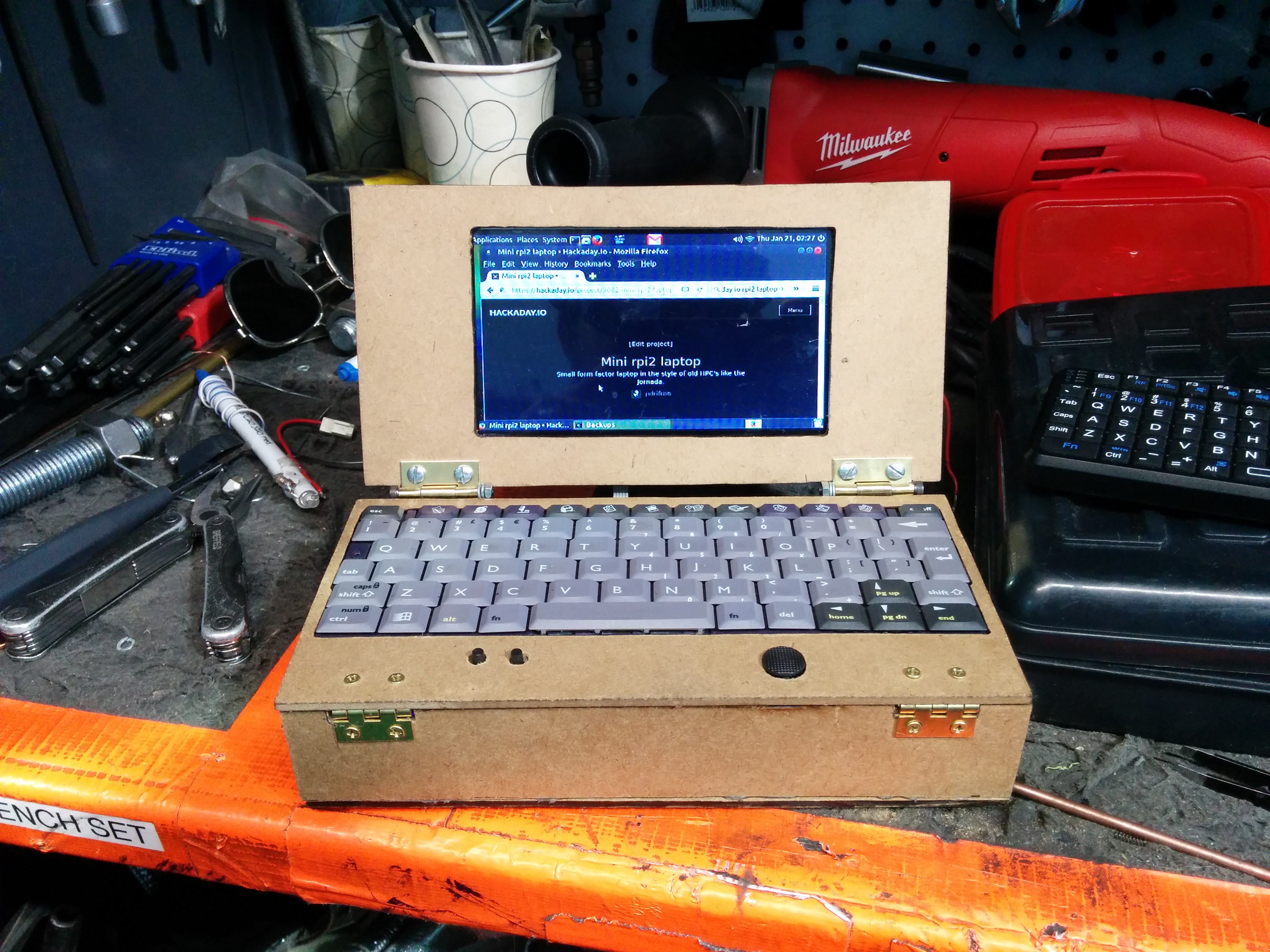
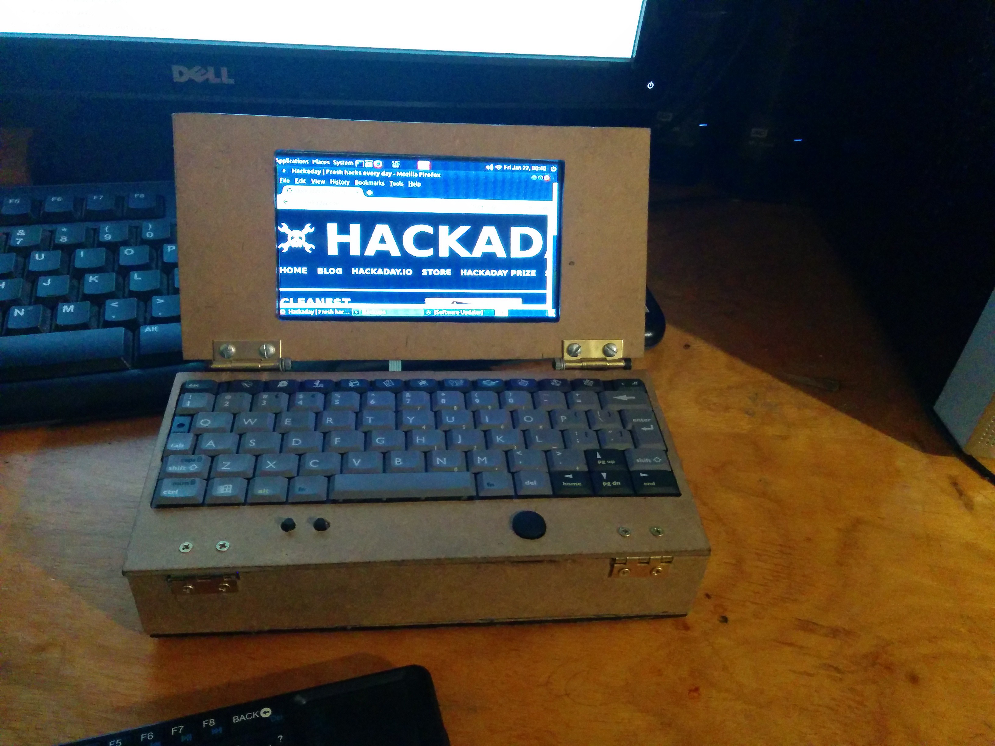
Here are some pics of me browsing my favorite site on the rpi2 laptop using a wireless keyboard. Hopefully I will not need it soon.
Well the teensy 2.0 ++ arrived yesterday (Friday). Good thing too because here in the north eastern US were getting hit pretty hard by winter storm Jonas and there was no mail delivery today.

There is a car somewhere in there lol.
Back on topic, I did some soldering last night on the teensy. I hope the pins I chose will be OK. The analog joystick is wired to what I hope are the analog pins. I finished up the soldering today and now I'm going to try and program it.
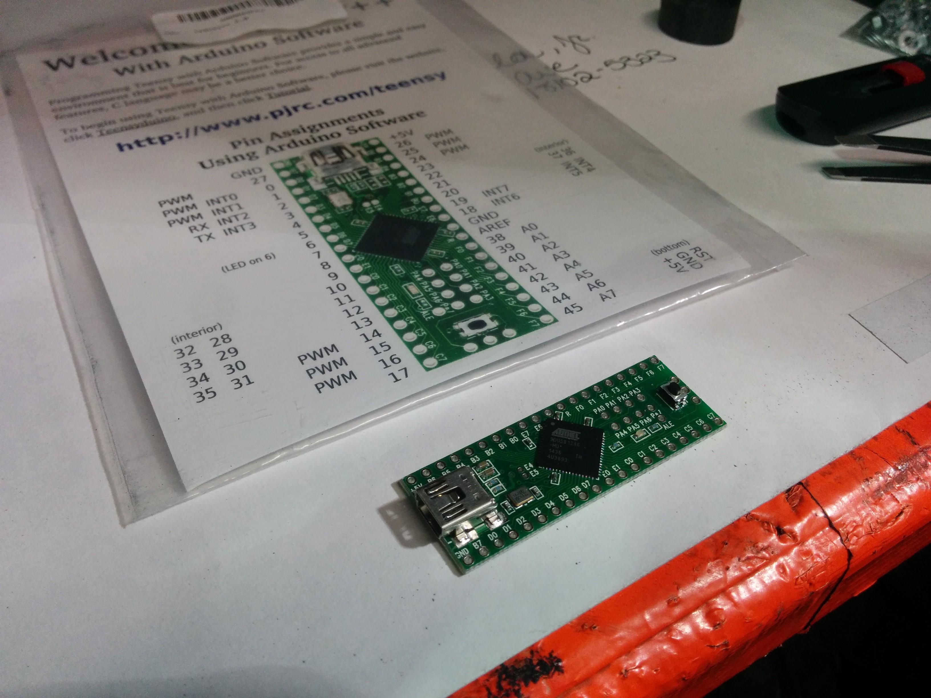
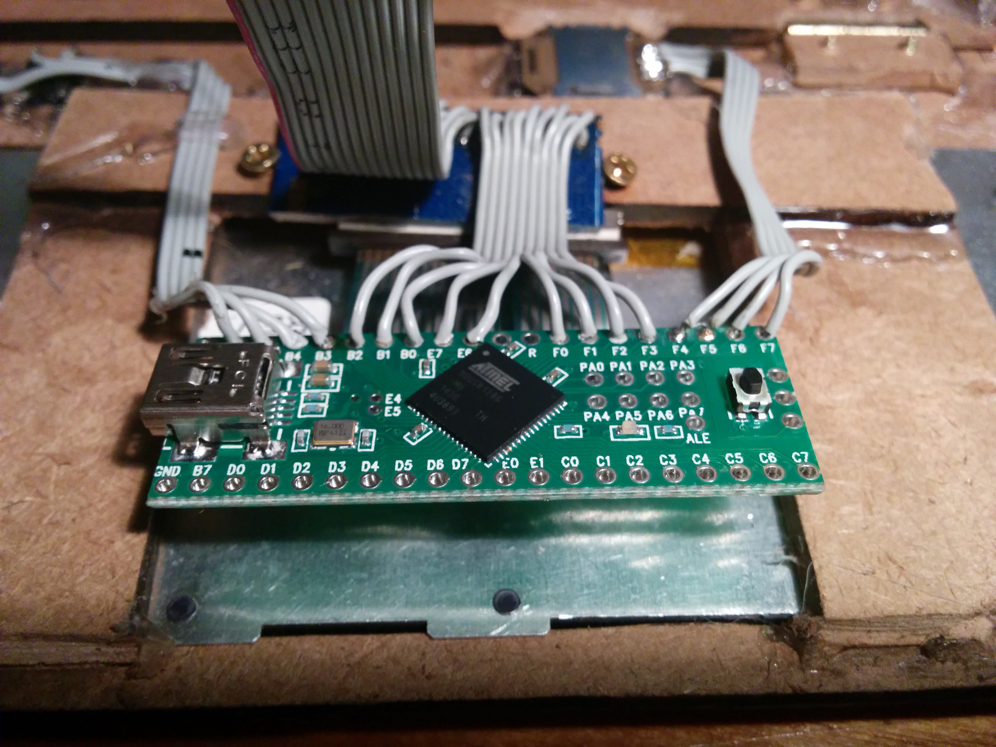
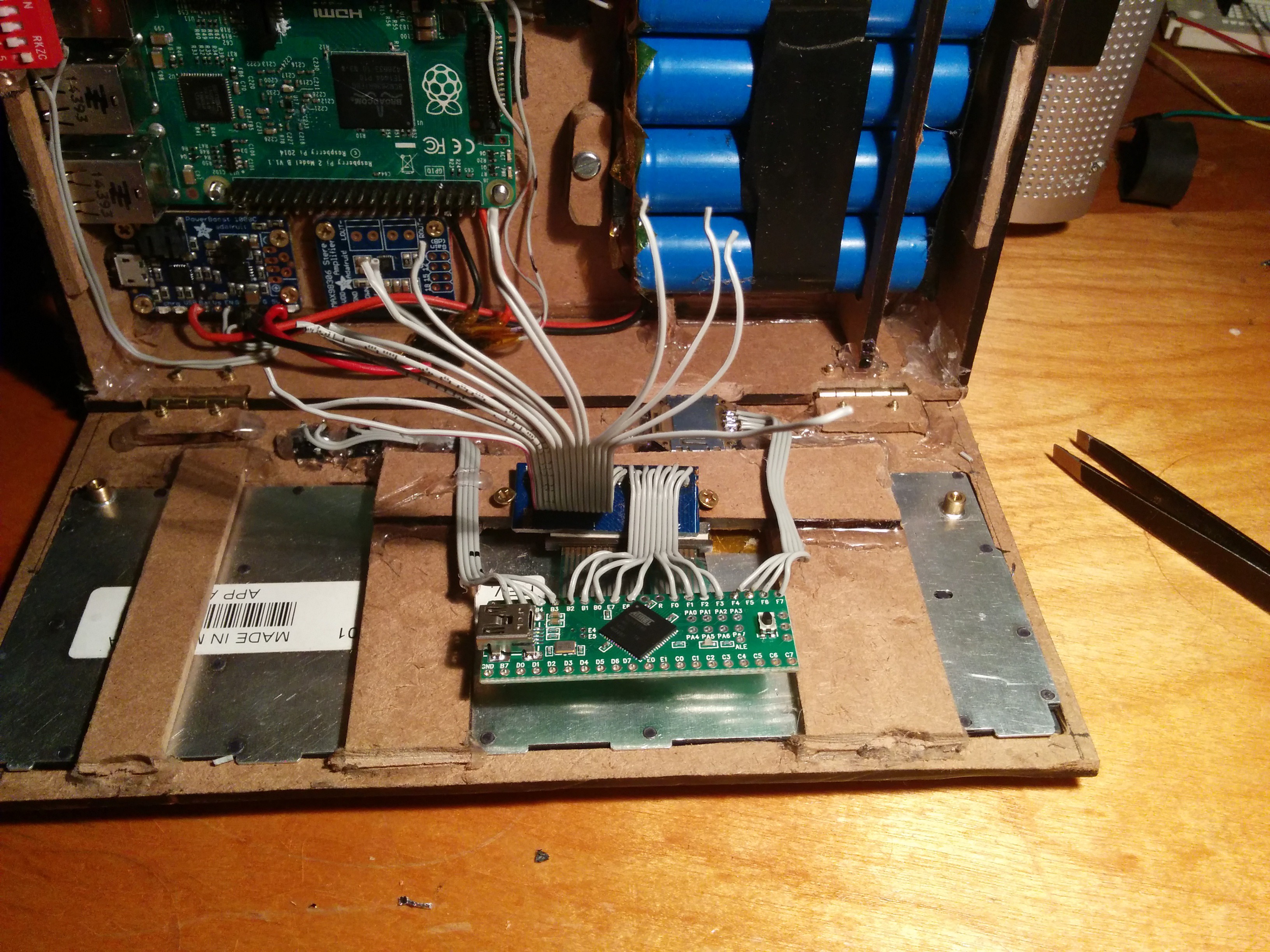
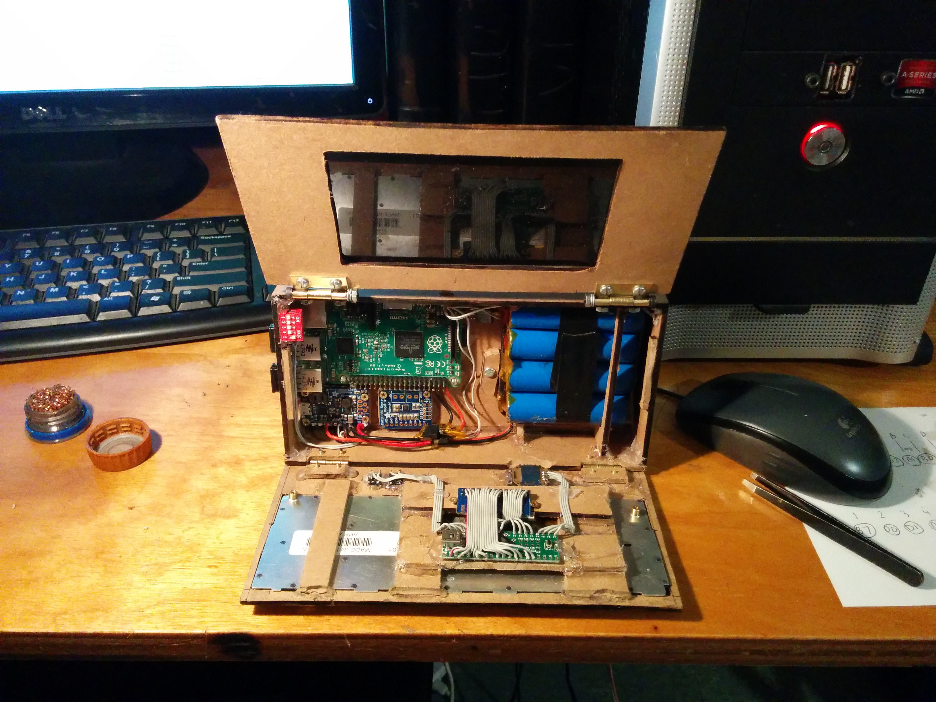
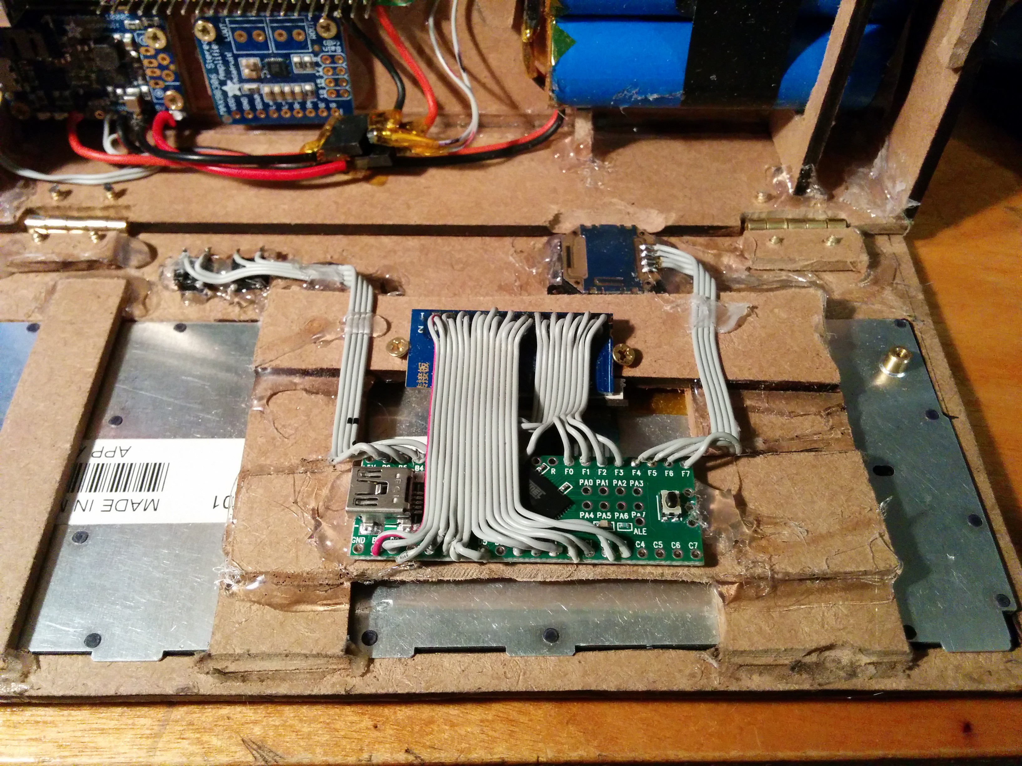
So now I'm working on programming. I'll post my results.
Well In all my excitement building this thing, I overlooked how many i/o I needed vs how many I have available on the teensy. I need 23 for the keyboard, 4 for the joystick, and 4 for the 2 pushbuttons. Unless I got it wrong on the 2 pushbuttons. Maybe I don't need 4. I'm not sure if i can get away with 3 if they share a pin. Either way, that's 31 pins of i/o that i need and the teensy 2.0 only has 25. I also have a teensy lc on hand but that still only has 27. I just ordered a teensy 2.0++ on amazon which should be here by Friday.
I'm not really sure on the wiring part. I have an idea and I'm looking in to it. The part I'm confused about is which pins to wire my components up to on the teensy. I think the analog joystick has to be wired up to analog pins, it has 4 pins and from what i found online they are ground, y axis, vcc, and x axis.
As far as the keyboard goes, i think any io pins should work as well as the pushbuttons.
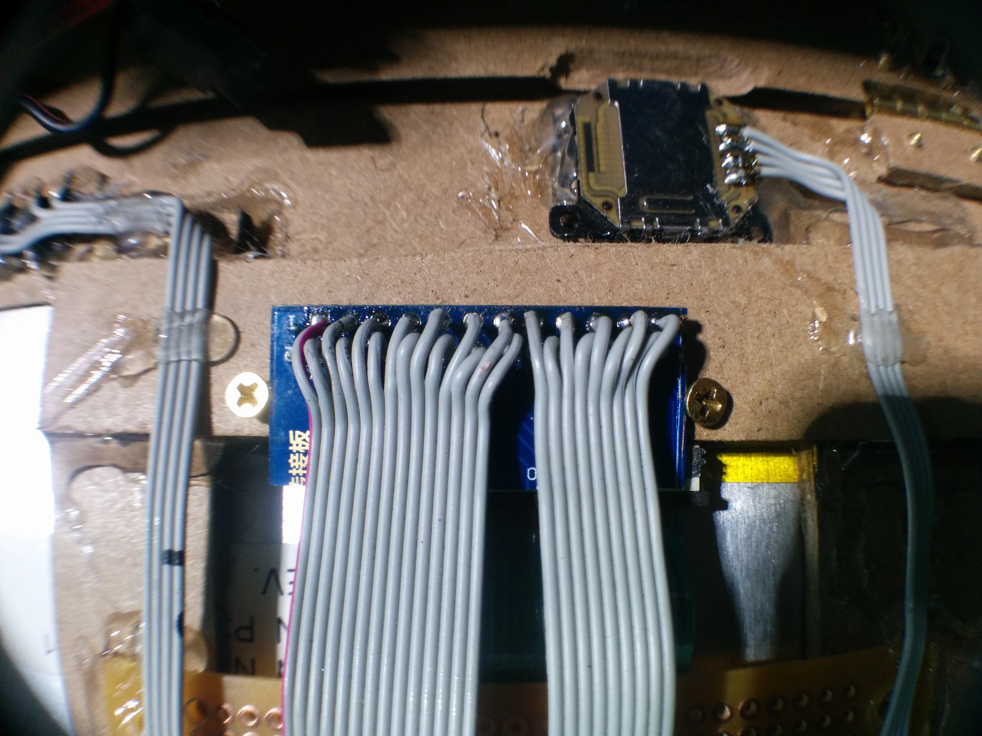
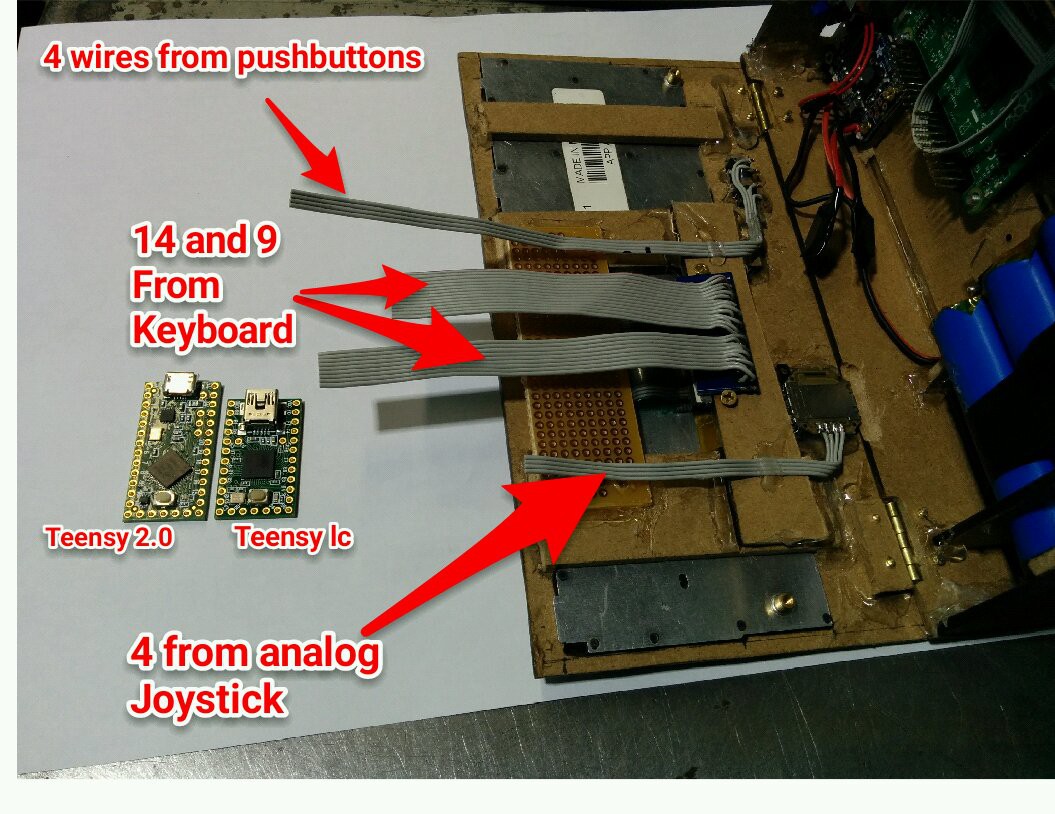
I could use some help with the wiring up of the teensy thing lol.
I've been working on this project in my spare time and I'm happy with the way its coming together. Its not perfect, but I'm happy and that’s all that counts since I’m making it for me. I had to wait for some parts I ordered. The fpc connector I got fit the
ribbon cable on the keyboard but I wasn't about to solder to that connectors fine pitch so I found this neat board on ebay that would make the job easier. So another 3 week wait and I was ready to move on.
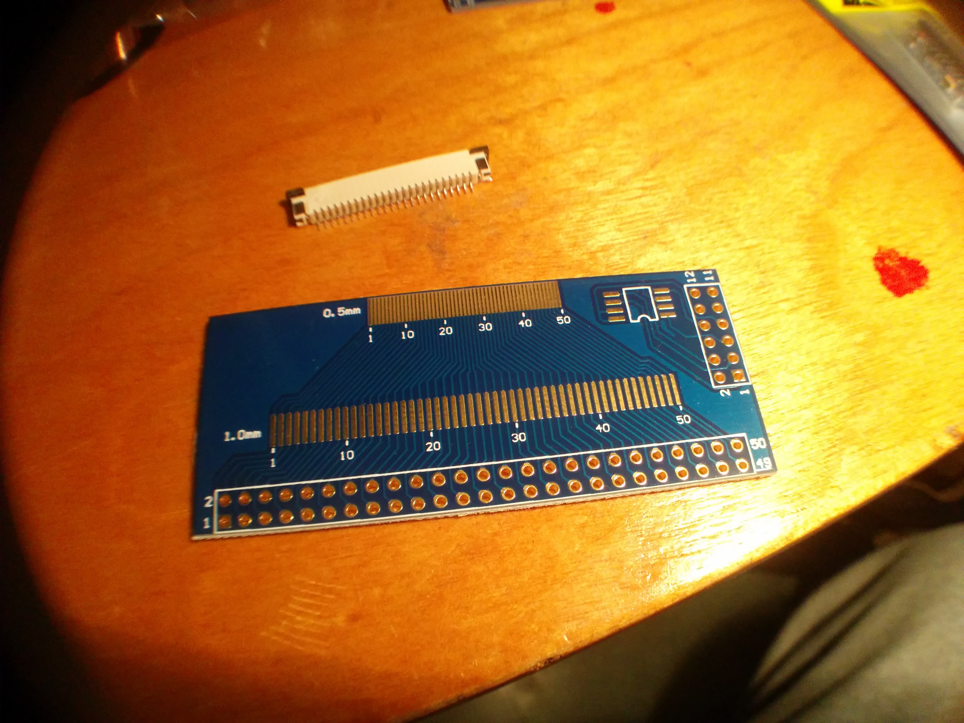 I didn't need the whole board so I trimmed it to save space.
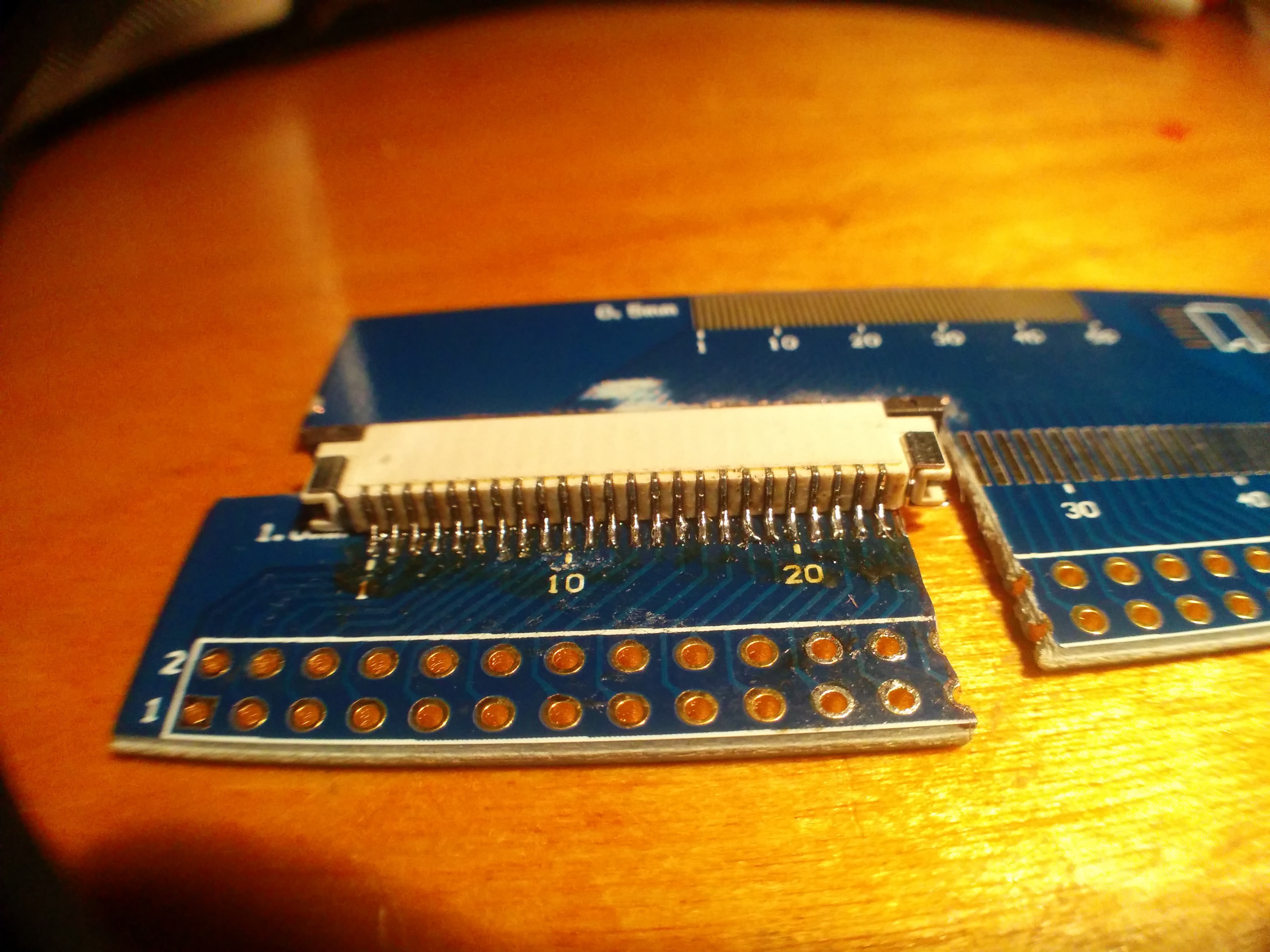
This is after trimming and soldering. It was tricky to solder the 1mm spaced pins. I used a big blob of solder on the end of my iron and I just rolled it back and forth over the pins slowly. That worked, I tested it and I managed to reverse engineer the pin out of the keyboard.
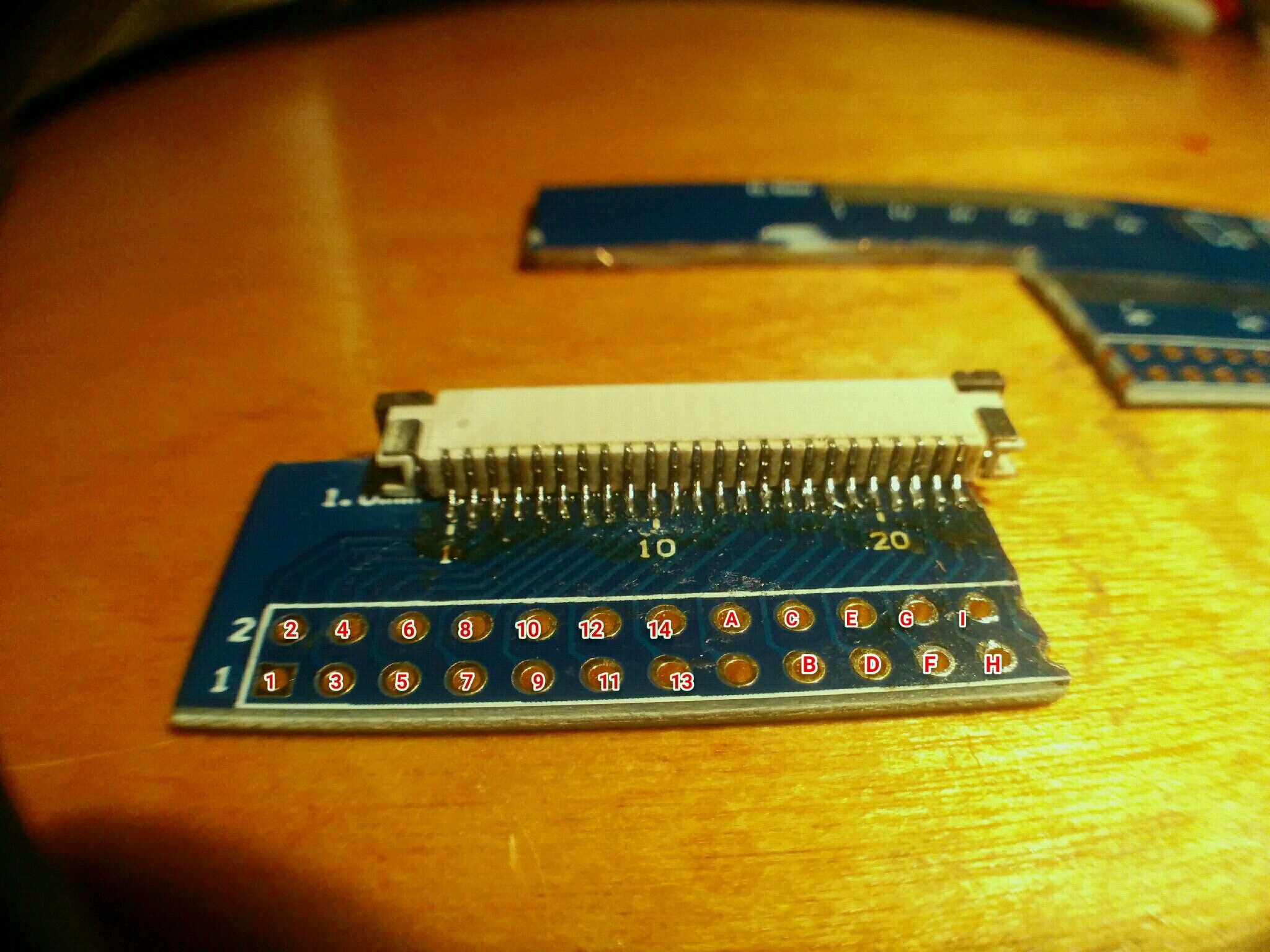
This is the keymap I got.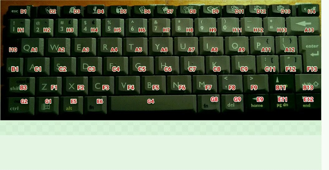
Then I worked on the case a little more. I had to route a space for the joystick so it would go through the 3mm board.
I used my dremel with a small drill bit to do it. First I tested it out an a scrap piece I had so I wouldn't make a mistake on
the case.
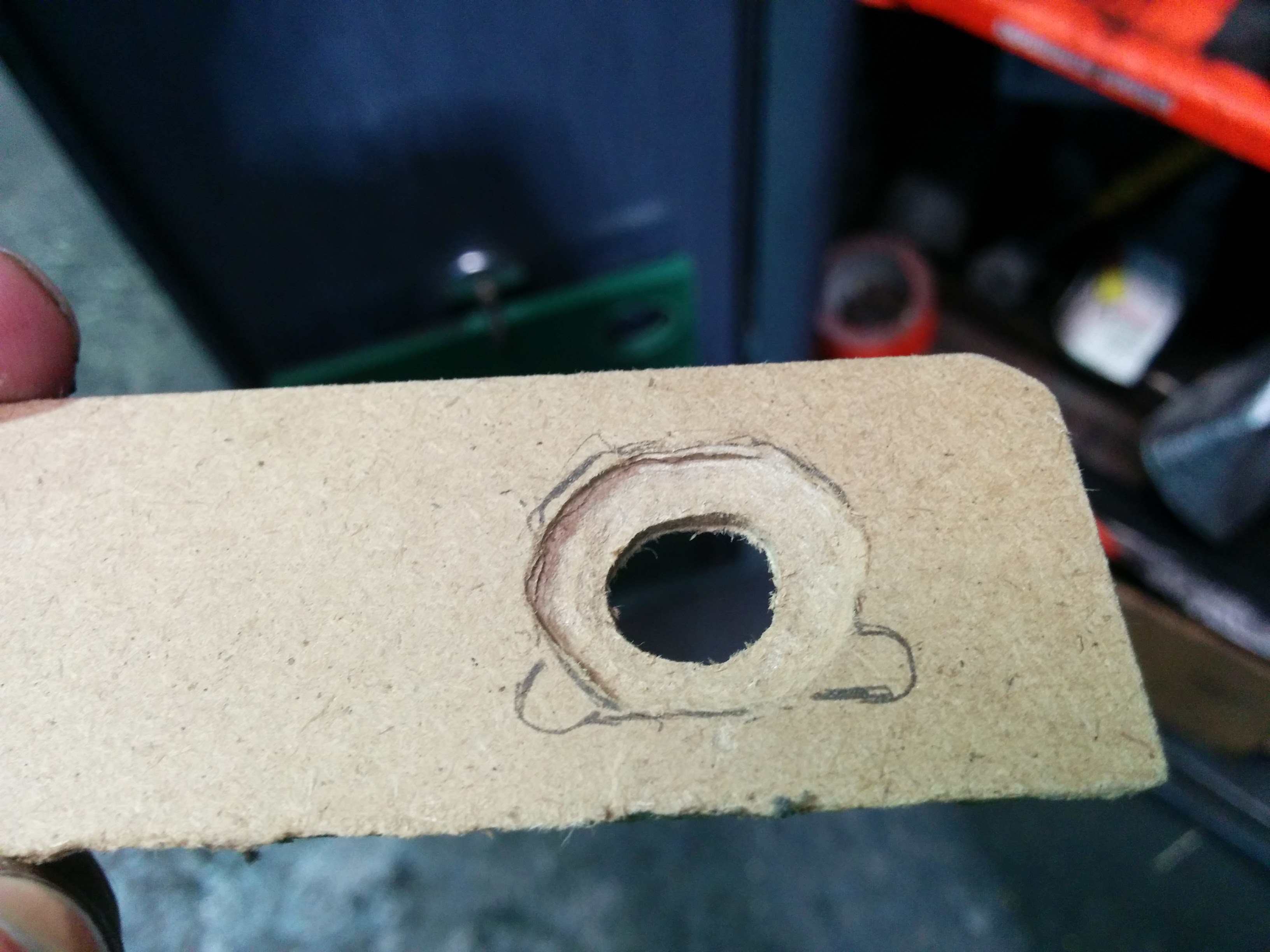
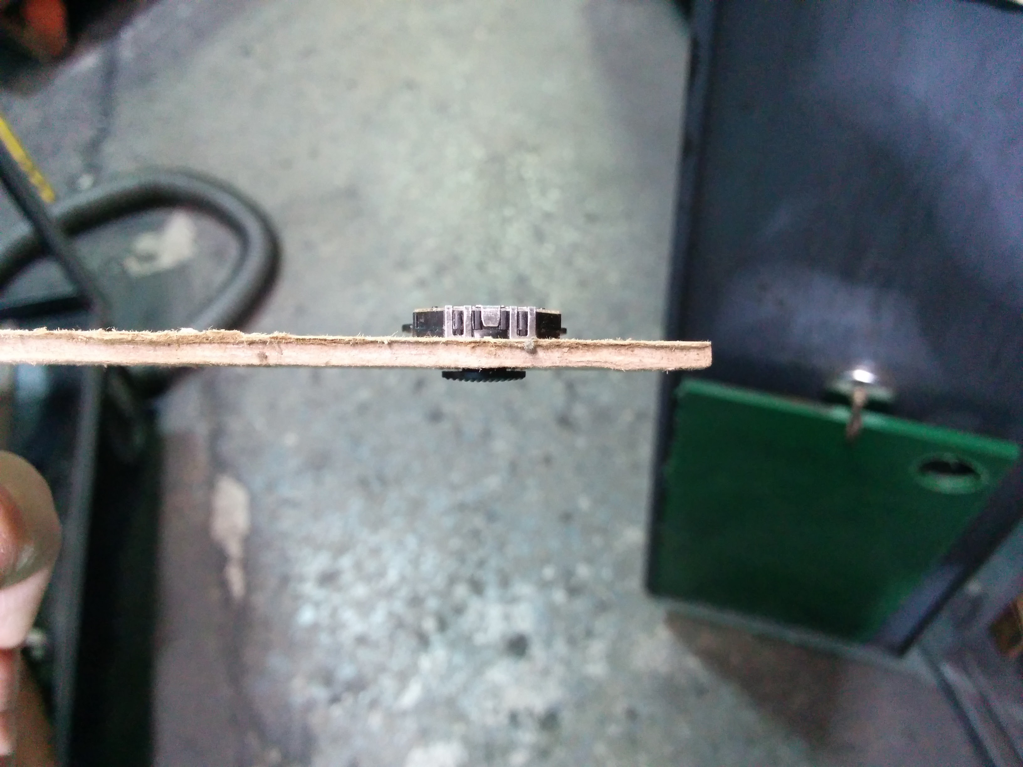
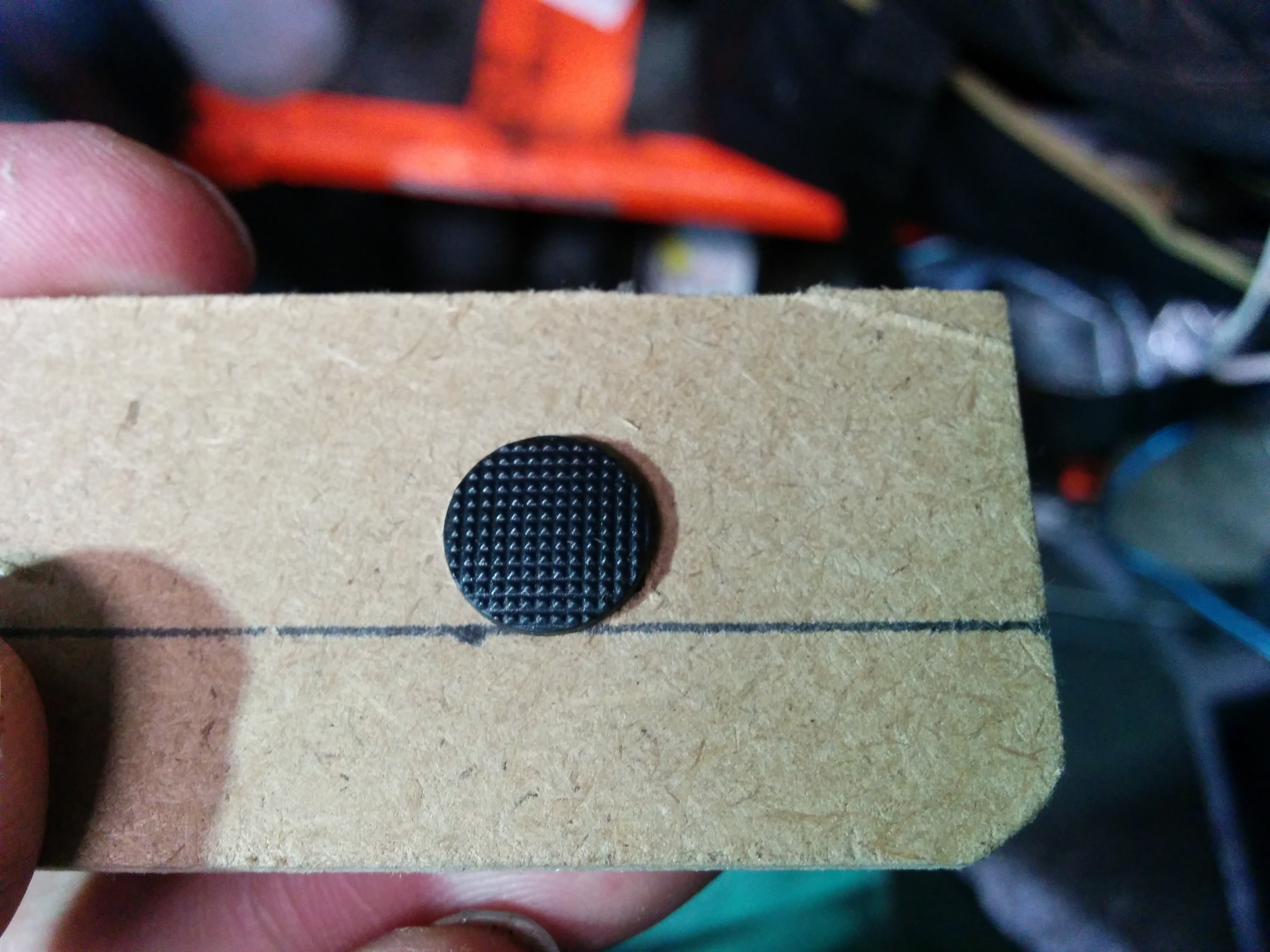
Once I was happy I did it for real.
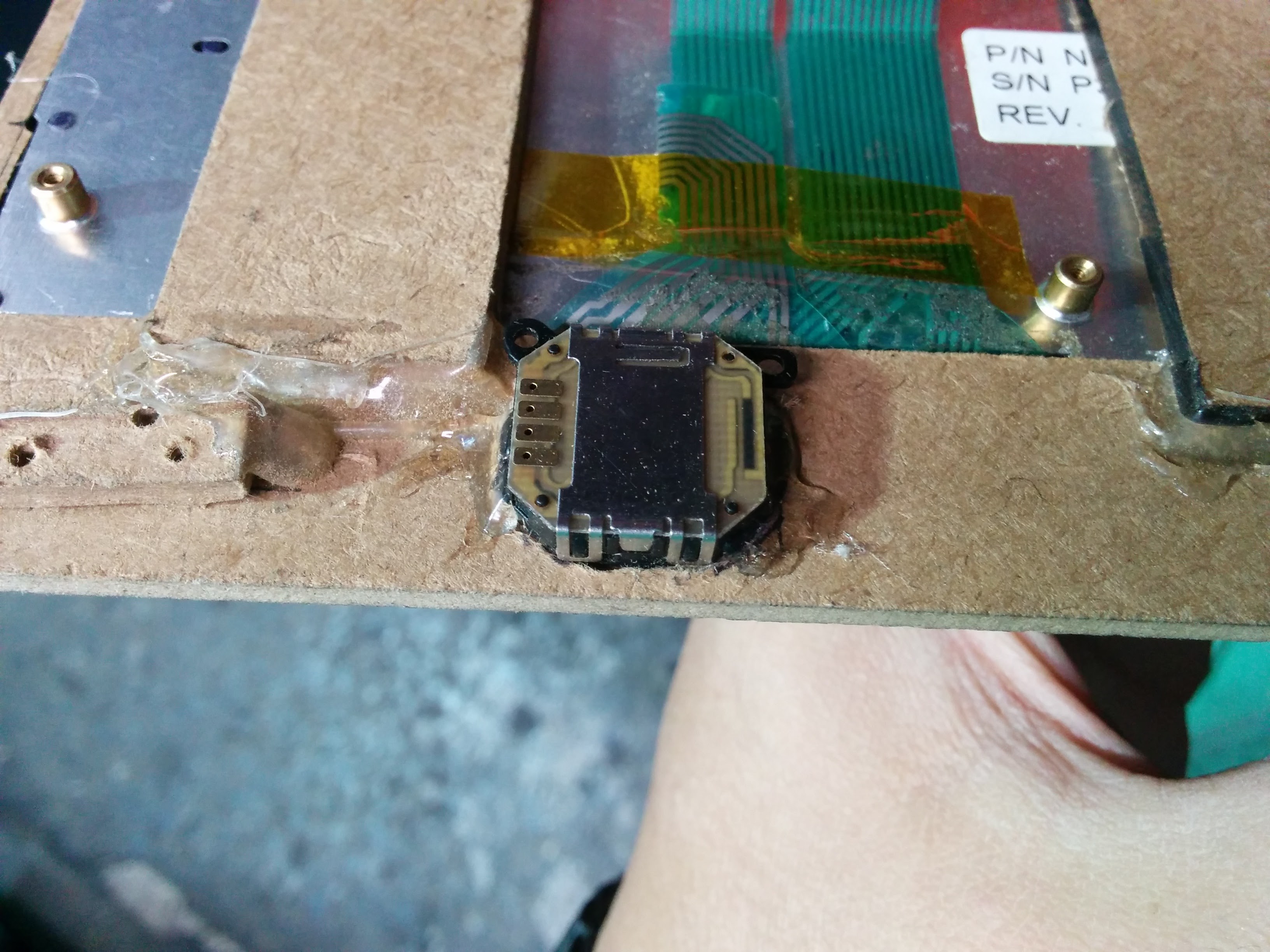
I had to notch the front panel so that it would fully close.
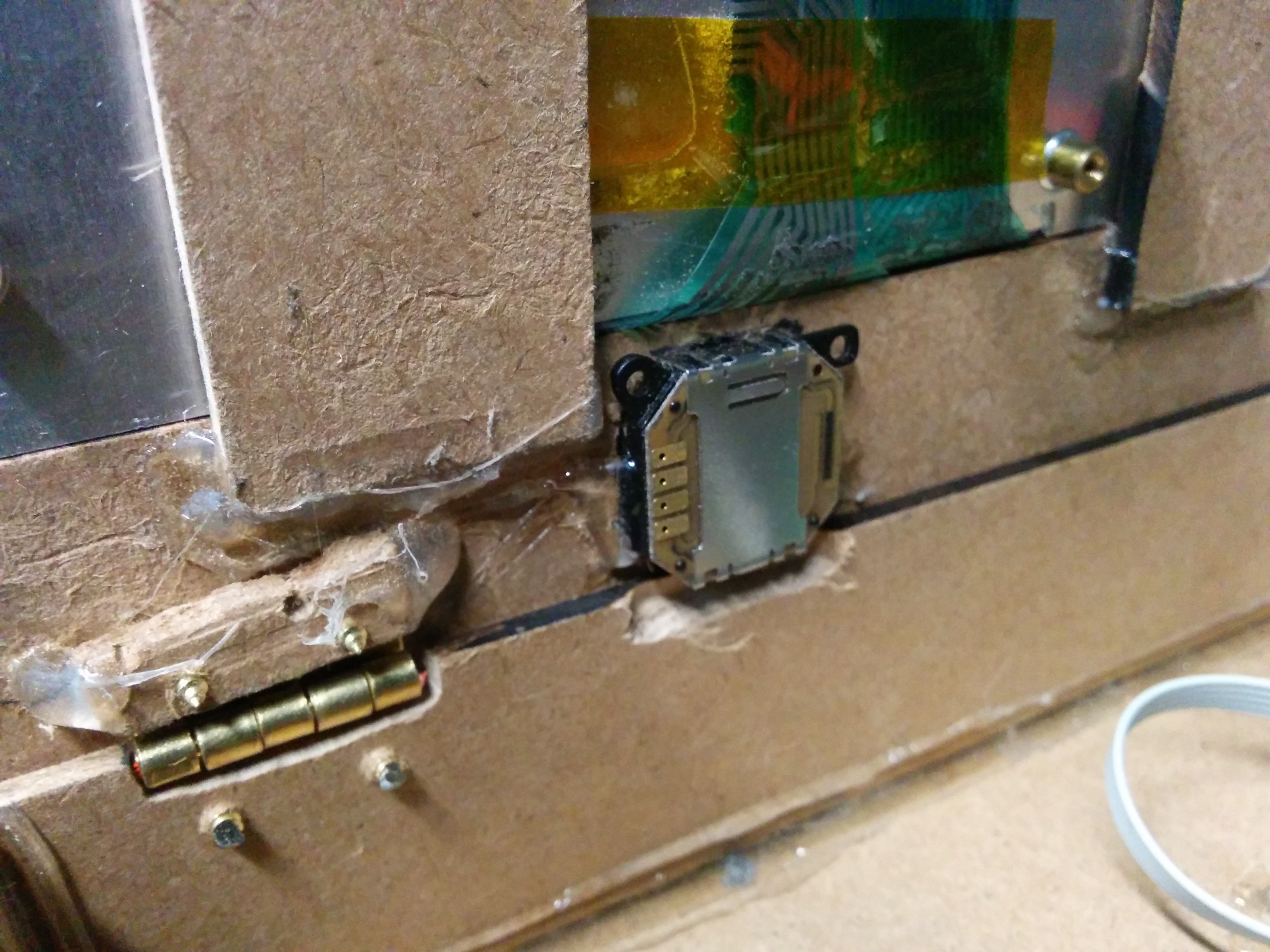
I made a bracket to keep the batteries in place and I mounted the powerboost.
I wanted to be able to easily access the inside so I mounted to top panel on hinges.
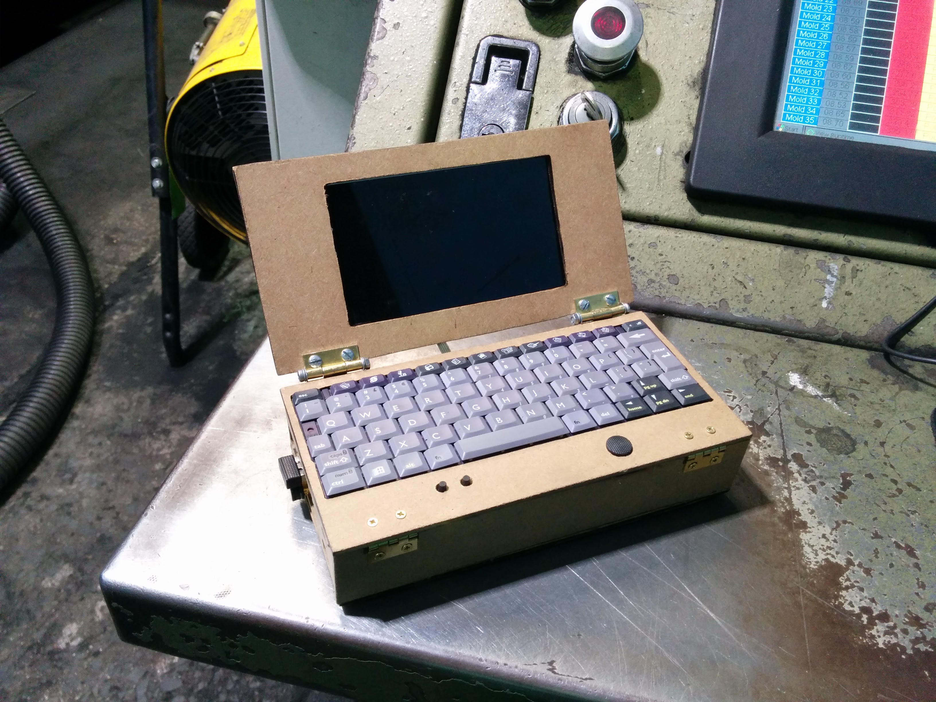
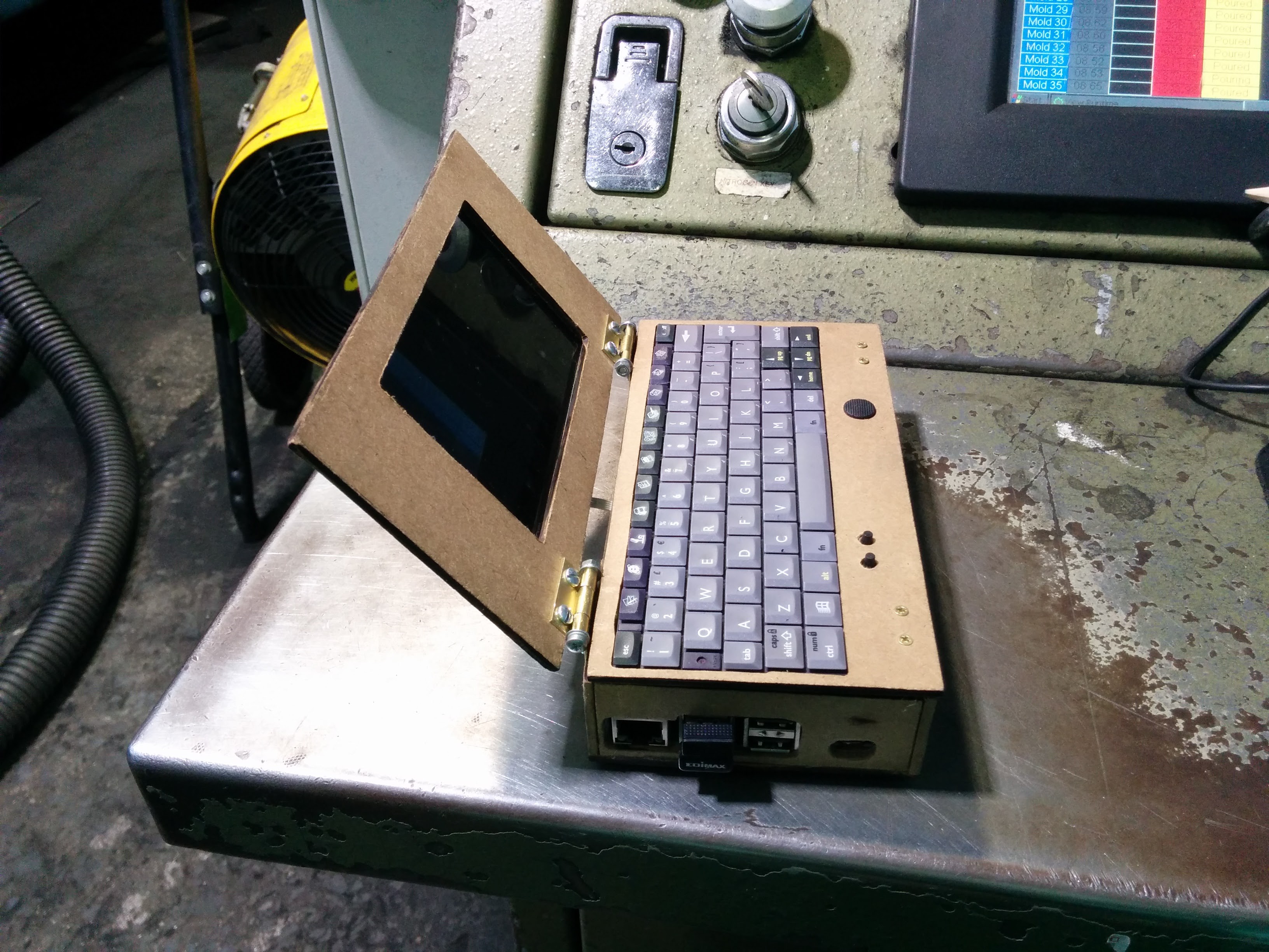
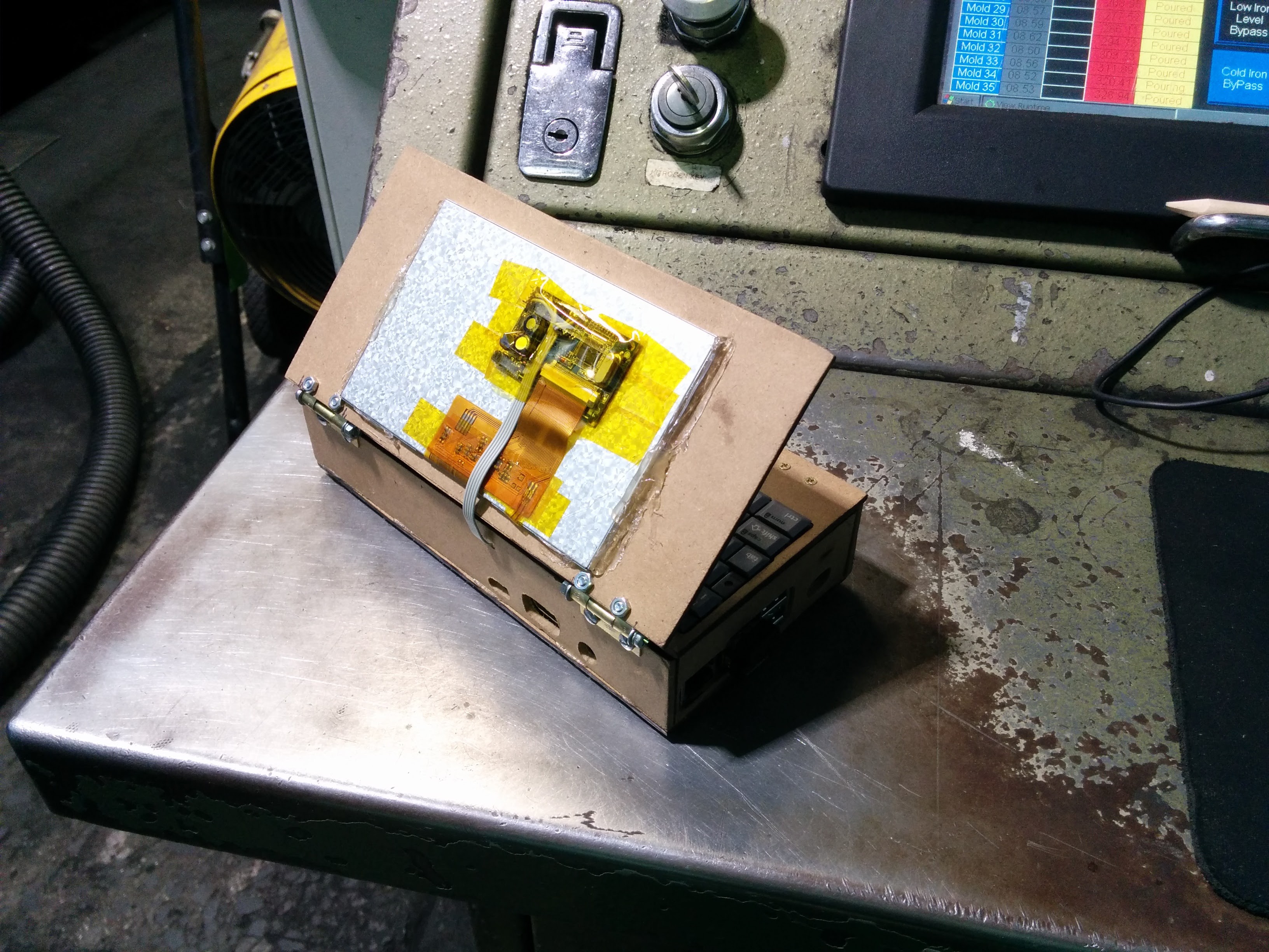
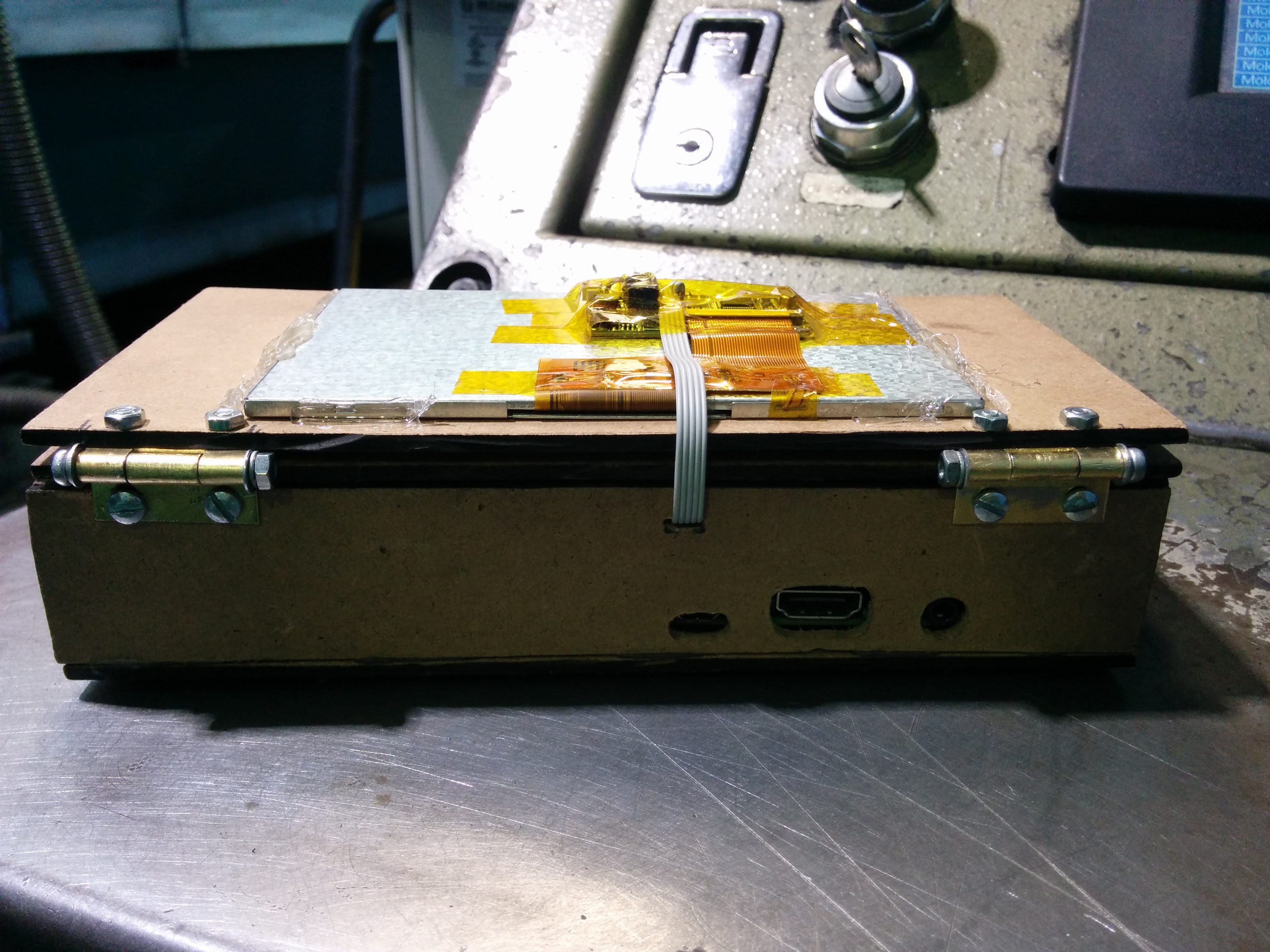
I removed the pin from the hinges and spread them open a little so I could fit M4 screws instead. With a lock washer on both sides I can adjust the resistance so that the screen stays open wherever I open it to.
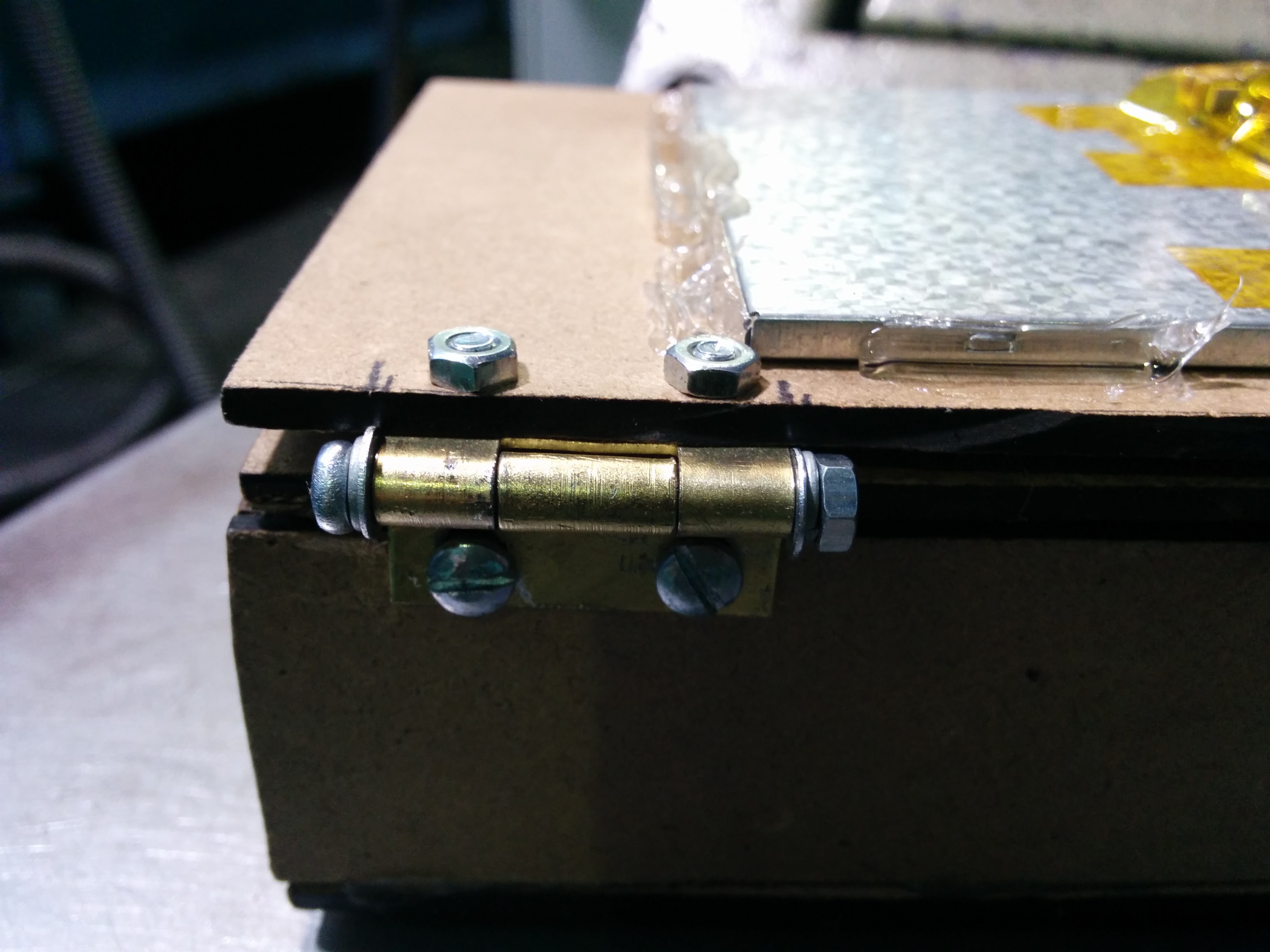
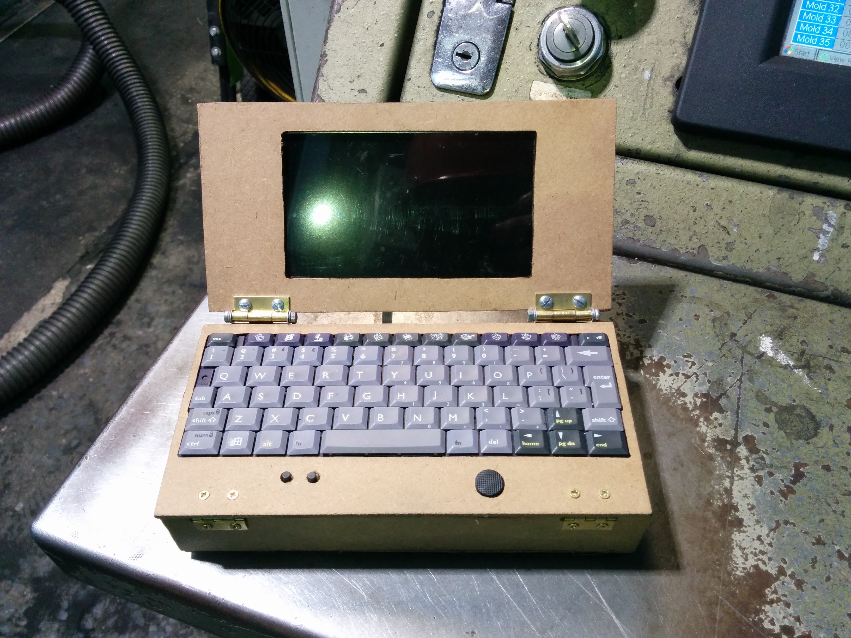
Now I just need to wire the joystick, 2 buttons, and keyboard up to the teensy and program it. I could use some advice with the wiring. The joystick has 4 wires, the 2 buttons have 4 wires and the keyboard has 23 which are split 14 and 9.
I will work on tgis tomorrow, I think it shouldn't be too confusing lol.
Well Ive been waiting on some parts from China. I haven't been able to work on the keyboard because I didn't have the connector for the ribbon cable but today it finally arrived.
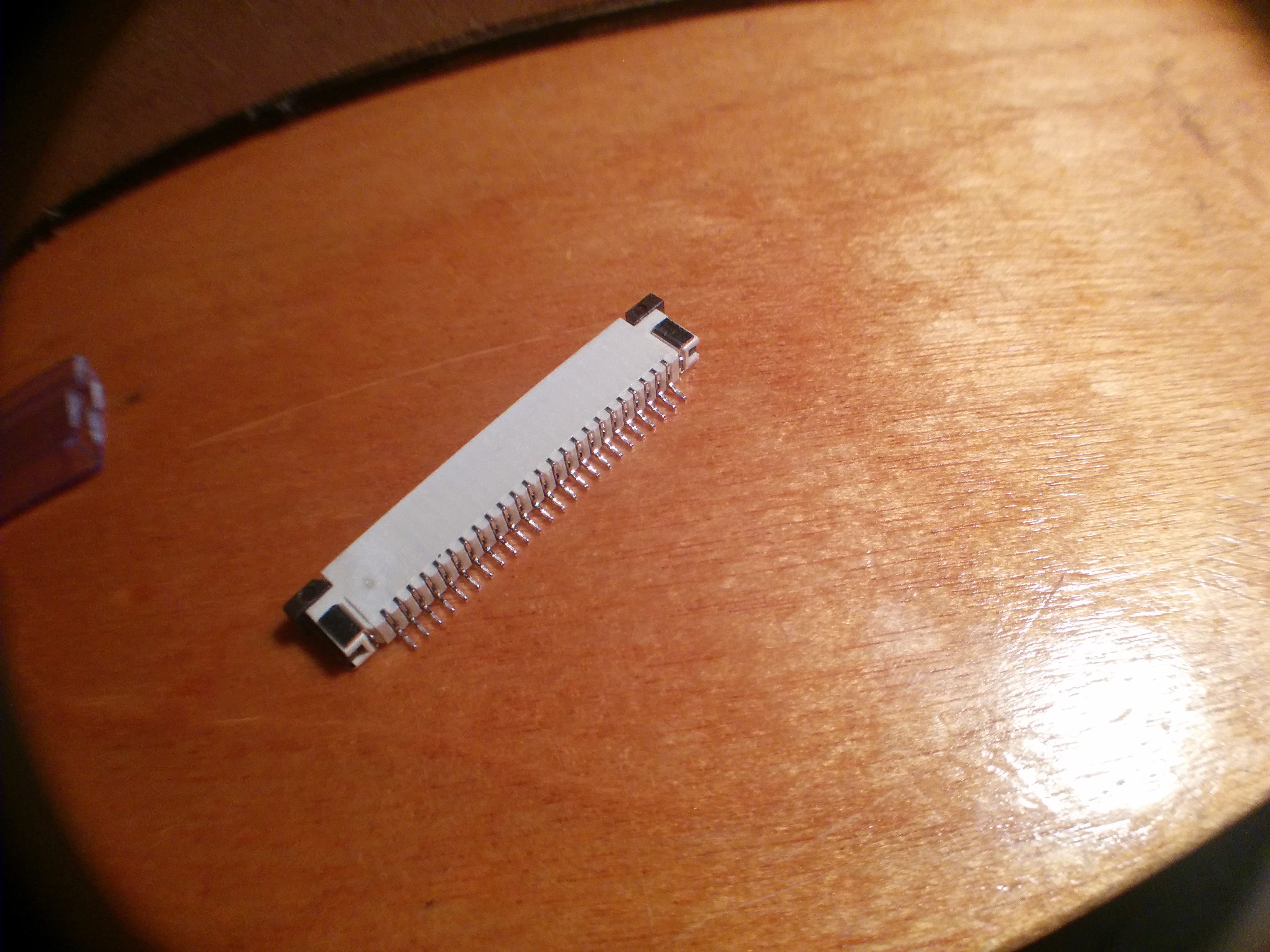
I ordered some 24 pin fpc connectors with 1mm pitch hoping that was the correct spacing and woohoo! It was.
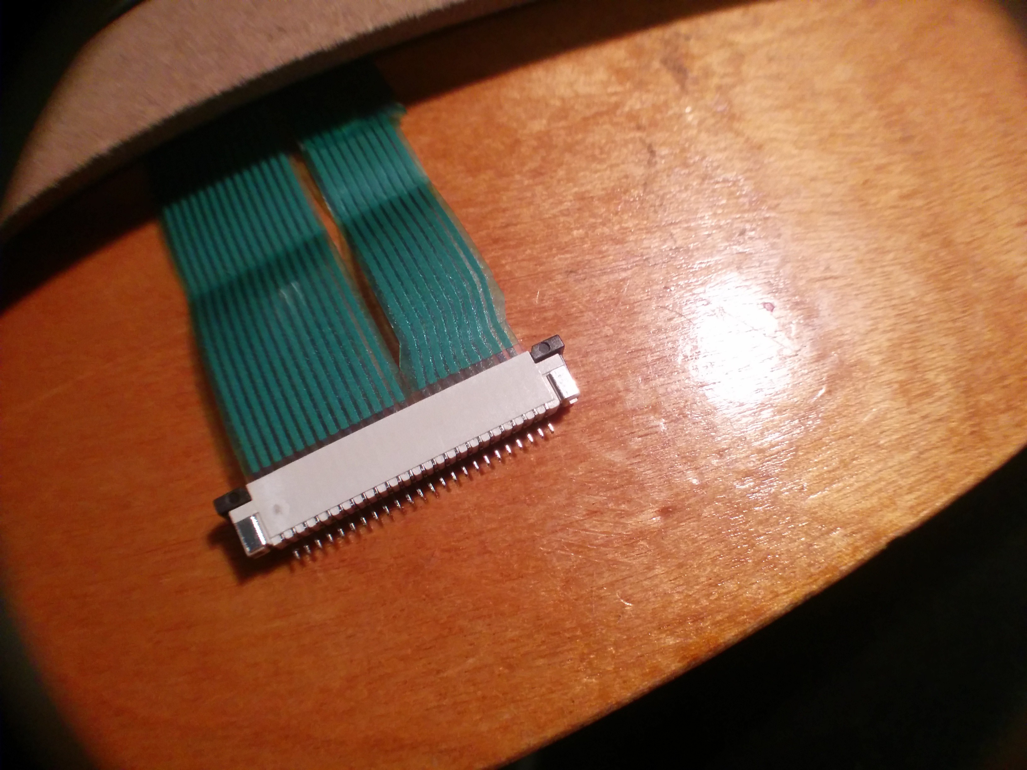
The cable only uses 23 pins but there is a gap so I was hoping a 24 pin connector would work. Luckily it does.
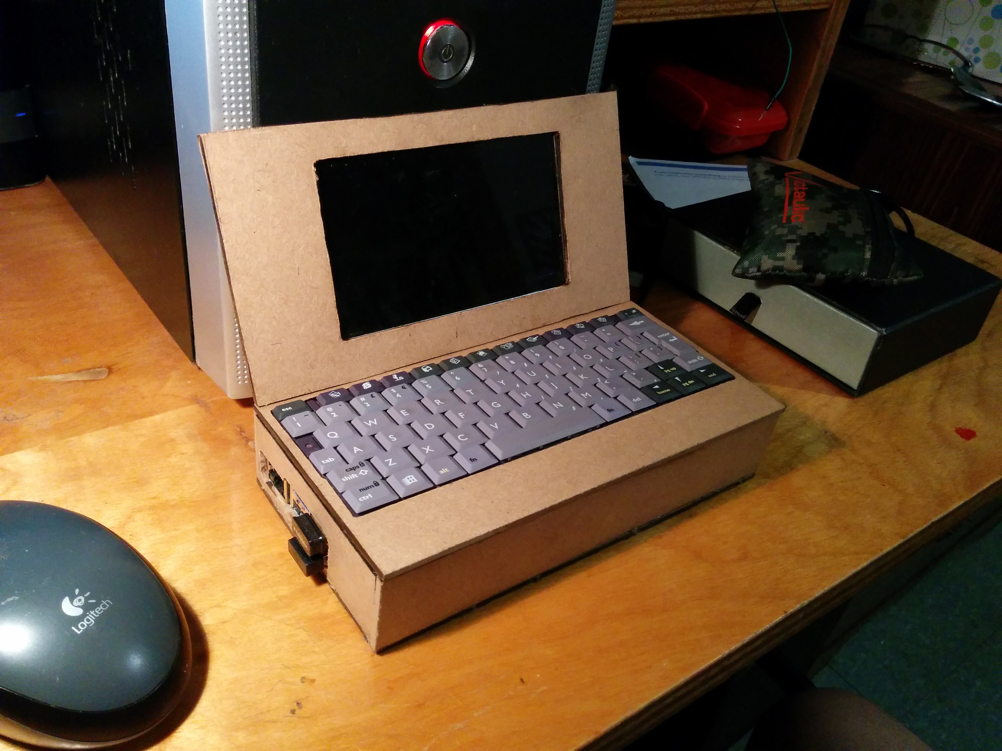
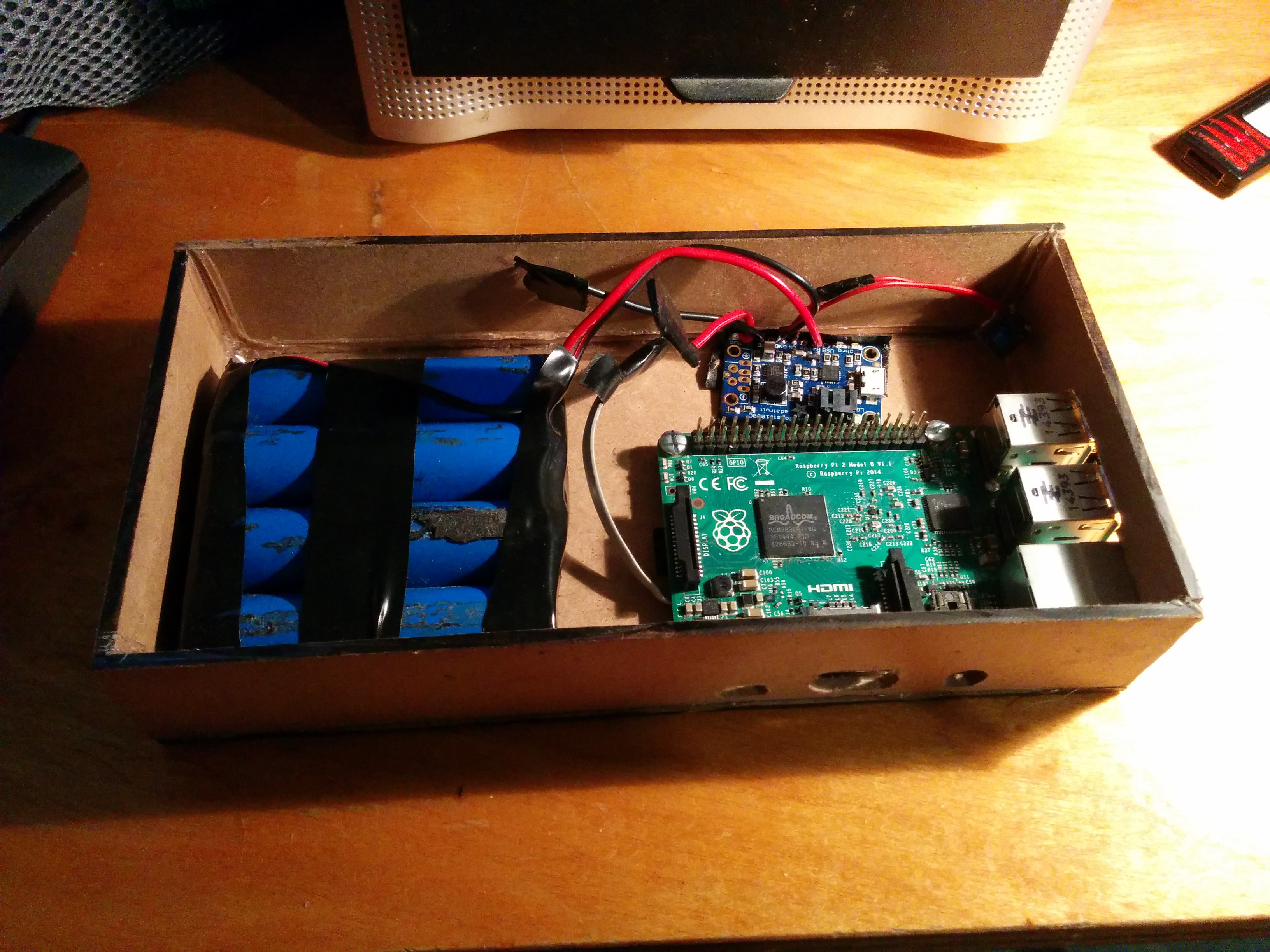
I also remade the housing and although it looks a little chunky, I will leave it as is for now that way i have extra space for more components if I need it. Here are some pictures of the housing.
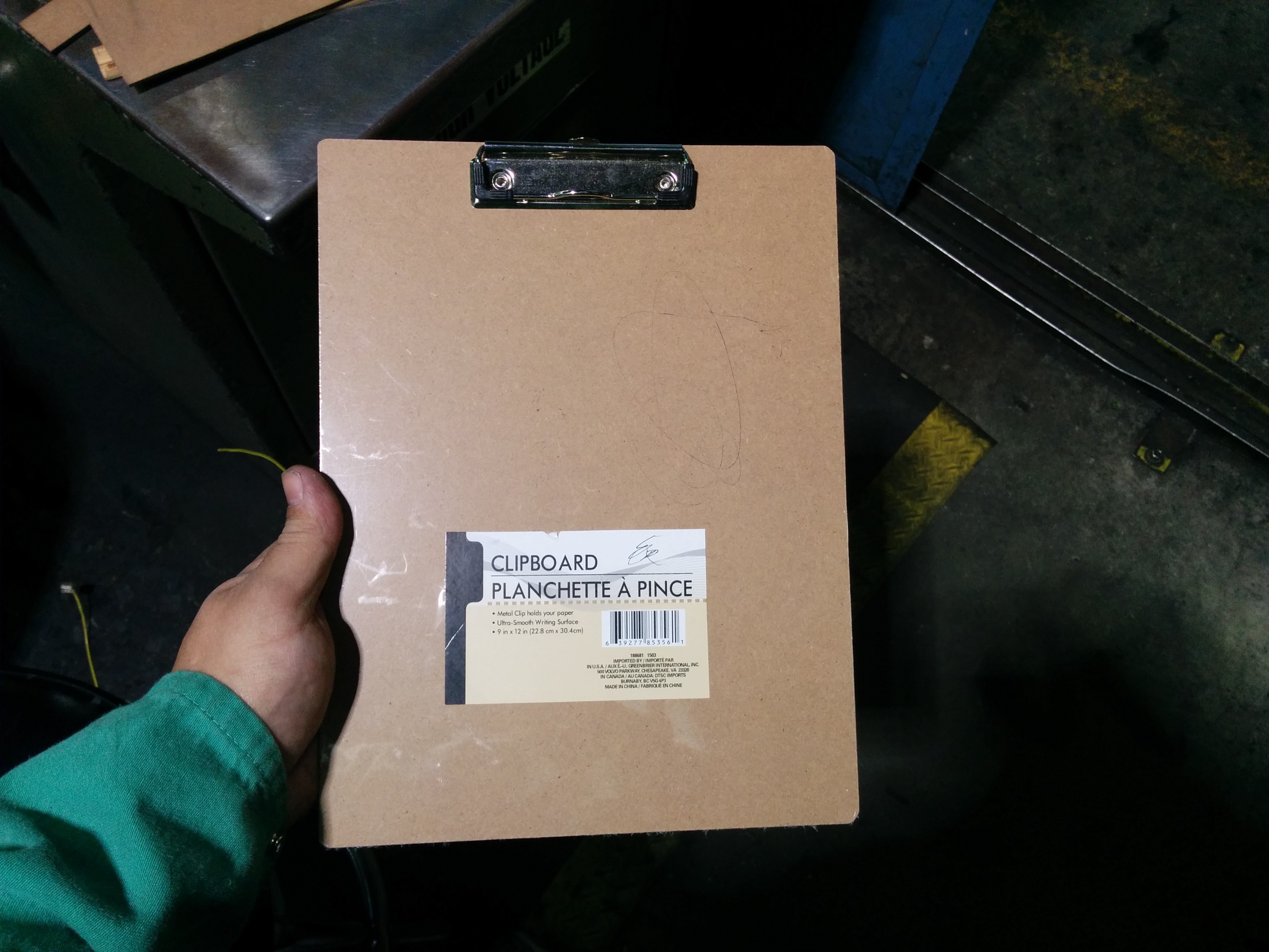
My source for thin mdf boards lol.
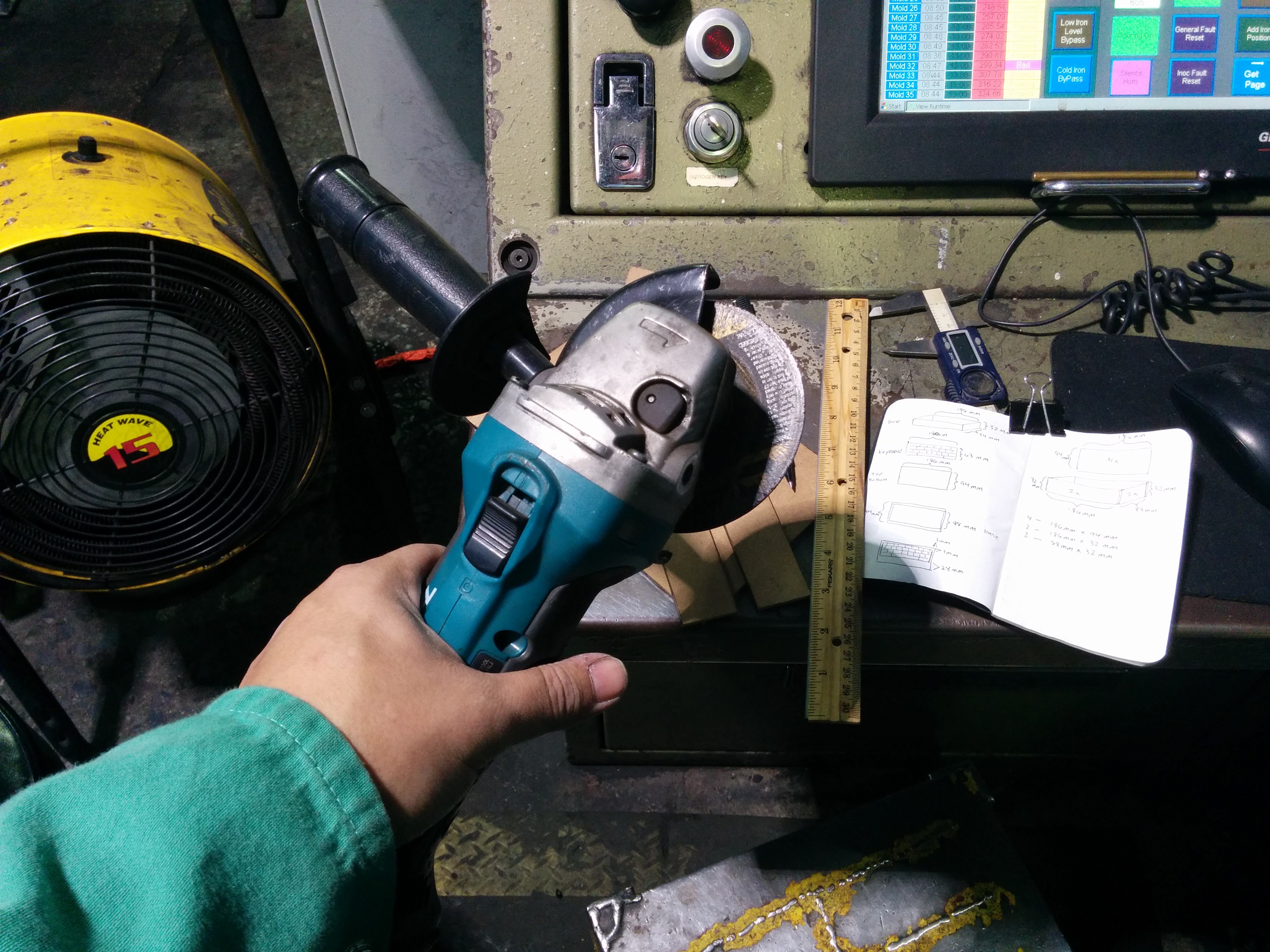
An angle grinder with a cutting disc makes quick work of the thin board. Maybe over kill but works for me. I finish up the cuts with a dremel.
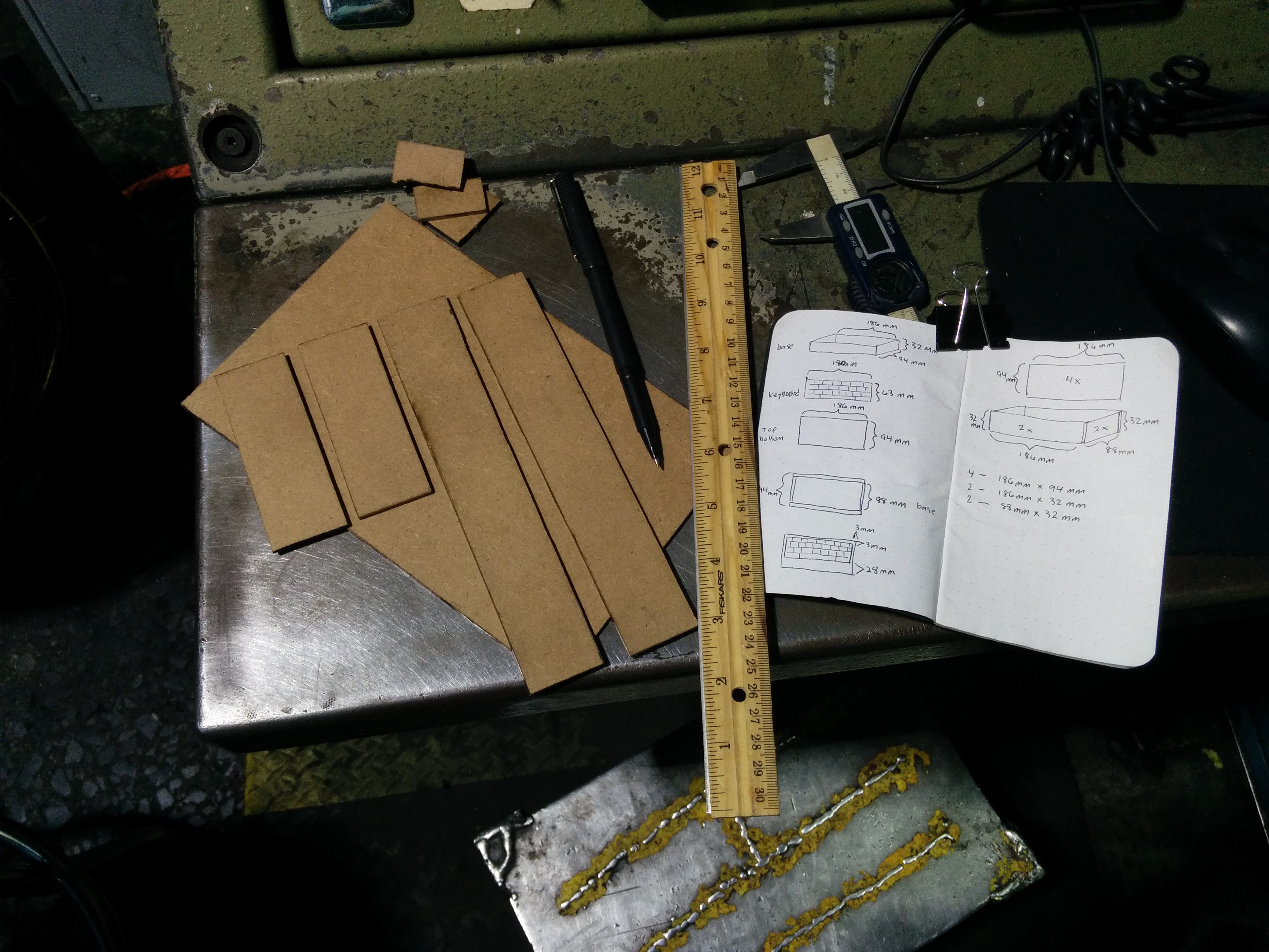 Pieces all cut out.
Like the first case, I hot glued it together.
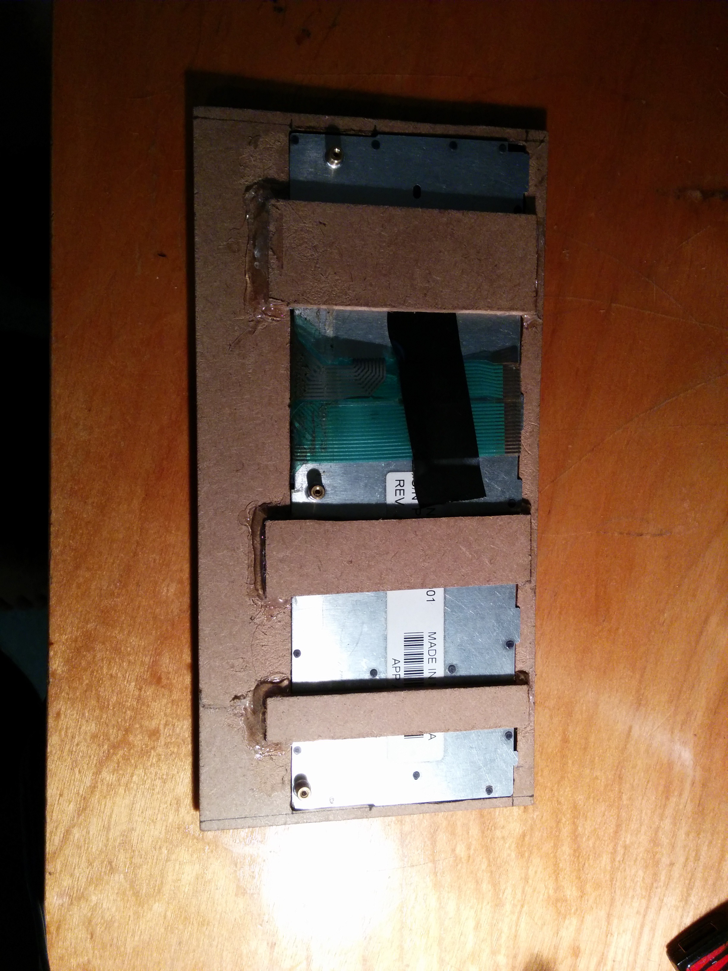
Bonus image,
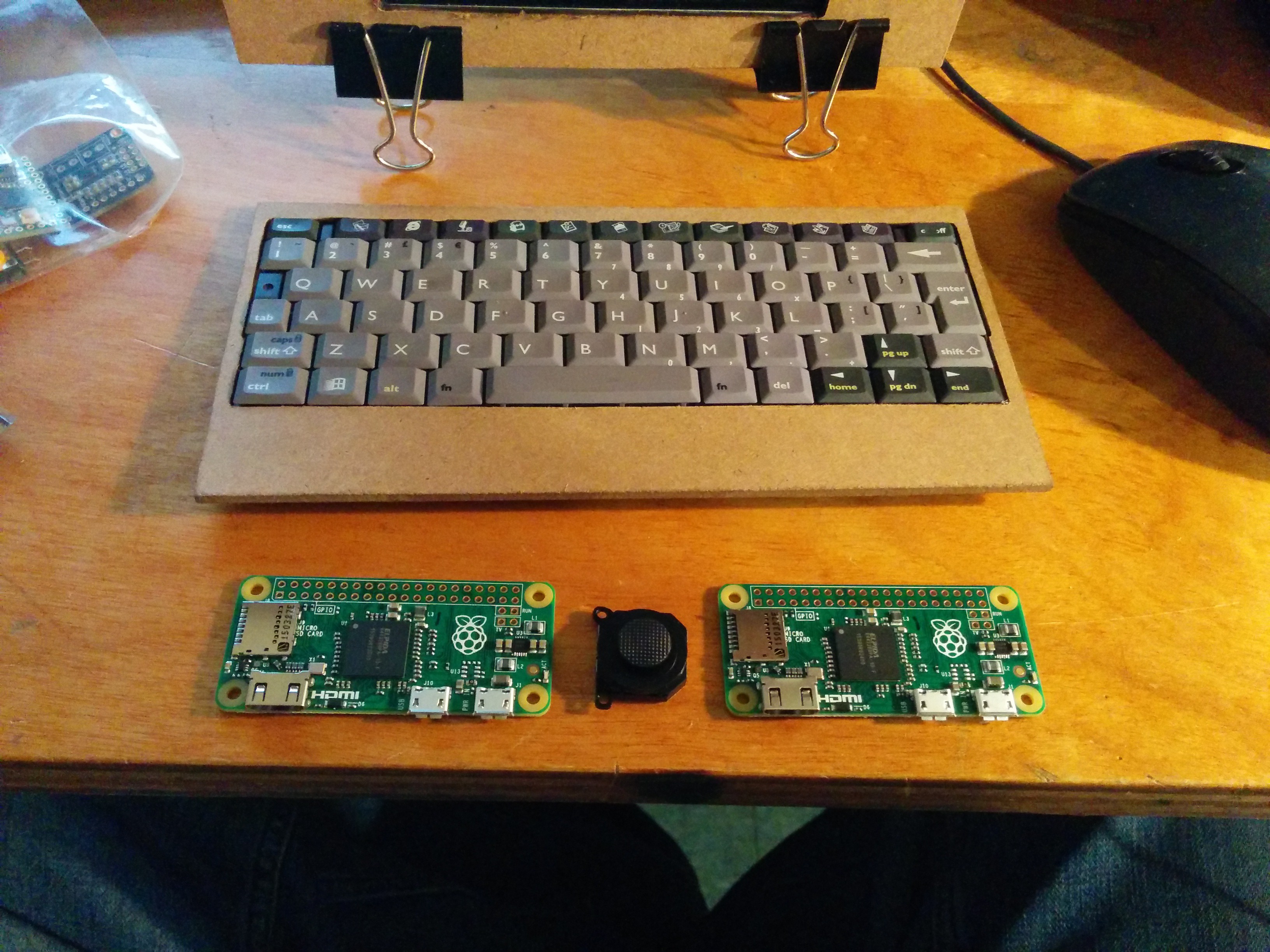
Woah what's this? My PI2 seems to have reproduced, Twins pi zeros!
I actually drove an hour away to the only Micro Center in Pennsylvania to buy those. They had 10 in stock but a one per household limit, so I had my wife purchase one using my mom's address lol. I haven't even powered them on yet due to lack of micro hdmi adapters. I just ordered a cable from amazon so I can try them out. Maybe I'll make an extremely tiny laptop with one lol.
Create an account to leave a comment. Already have an account? Log In.
Thank you for the nice comments. I really don't have plans to make a better case right now. I like it this way. If it breaks i can just cut another piece out and glue it on. Or if I want to modify the layout, easily done.
Great! I'm going to be teaching a class with kids and the raspi, and I will use this case as one example of what they can do. And the advantage of repairable will be highlighted.
Great project!
I used the Powerboost and 4 x 18650s in my #Pi Video Player and had nothing but bother with them; I had 3 of them release blue smoke, all from different components.
I love the board, but at the same time no longer want to use them and want to find an alternative.
I just installed it yesterday. Seems to be working ok. I was getting around 6 hours from the batteries before. I had used the circuit from a portable battery charger (as well as the 18650's). It took all night to charge and I couldn't use it while it was charging. With the power boost I can so i think it was worth switching to it.
What is your pi player case made out of? Looks like laser cut mdf to me.
Ah, glad yours works so far :-) I got a few days of use out of the circuit and then the various smokes started to appear ha ha.
Depending on your 18650's capacities the powerboost could still take a wee while to charge but it is a great circuit. I'm gutted mine didn't work.
My case is indeed MDF - 6mm thickness. I had won a $100 Ponoko coupon so I thought i would treat myself :-)
I love laser cut enclosures for projects such as ours; gives a great finish!
I bought this one :
http://www.amazon.com/gp/product/B00GX49AG2?ref_=cm_sw_r_other_awd_CqkJwbWT8G67N
and it works with 5 volts but it certainly isn't hd like they claim. They claim it's 800 x 480. I don't know how to tell but I doubt it.
I don't recommend it if you want HD.
I almost forgot that the lcd is defective. No matter how I edit the config file the image on the screen is always cut off on the left. I'm using it for now but I am going to buy a better one. Maybe touch screen and hdmi.
Become a member to follow this project and never miss any updates
 deʃhipu
 Patrick Tait
 RasmusB
I have to say I love this case! The "prototype" appearance is just exactly the esthetic that I manage to achieve in all my wood working! LOL... Now you will probably go and spoil that for me at some point by cutting the final design out of a lovely hardwood, and giving it a finished professional look but using a clipboard and hot gluing it together is genius! And I really appreciate your showing it to us during the early phase.