Daniel Frausto
-
Trying to catch up...
03/27/2016 at 11:43 • 0 commentsThis week has been slow, but will get back on track by monday. Gonna have some time today to make some mock-ups of the case. Stay Tuned.
-
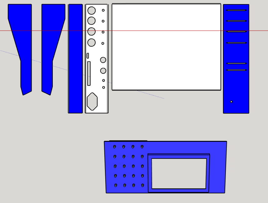
Exporting the paths....
03/14/2016 at 06:21 • 0 commentsNow I have Finished exporting the paths to a dxf file that will be used in a Cam program to create the cnc paths( G-Code ) to be used to route out the case from the material...likely to be acrylic. take a look.
![]() If you want to check it out, the *.DXF will be in the Download Section... it's uploading as we speak....
If you want to check it out, the *.DXF will be in the Download Section... it's uploading as we speak....UPDATE: HERE IT IS.
-
Done! (With the Layout) ...almost.
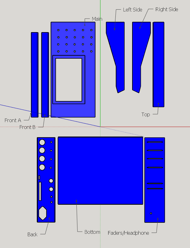
03/14/2016 at 05:53 • 0 commentsWell I separated all panels. All unnecessary parts where removed... if you can tell i did not add the USB port because i am planning on having them mounted on aluminum panel... then than panel will be added .Check it out. Files are in the Download Section Named OnlyCase.
![]()
![]()
-
The case to build...
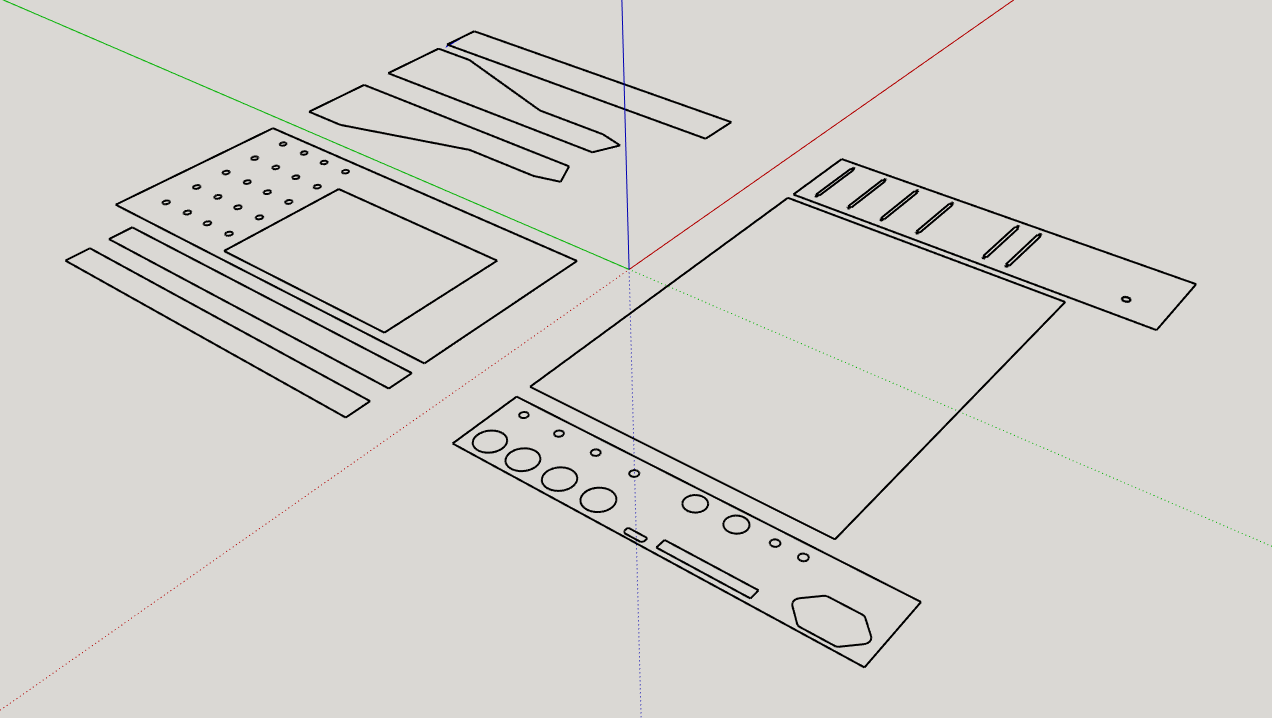
03/14/2016 at 05:04 • 0 commentsStarted to layout the panels that will create the case. Still moving things around but most likely will use a cnc to cut the case out of acrylic....Take a look.
![]()
-
It's Here!
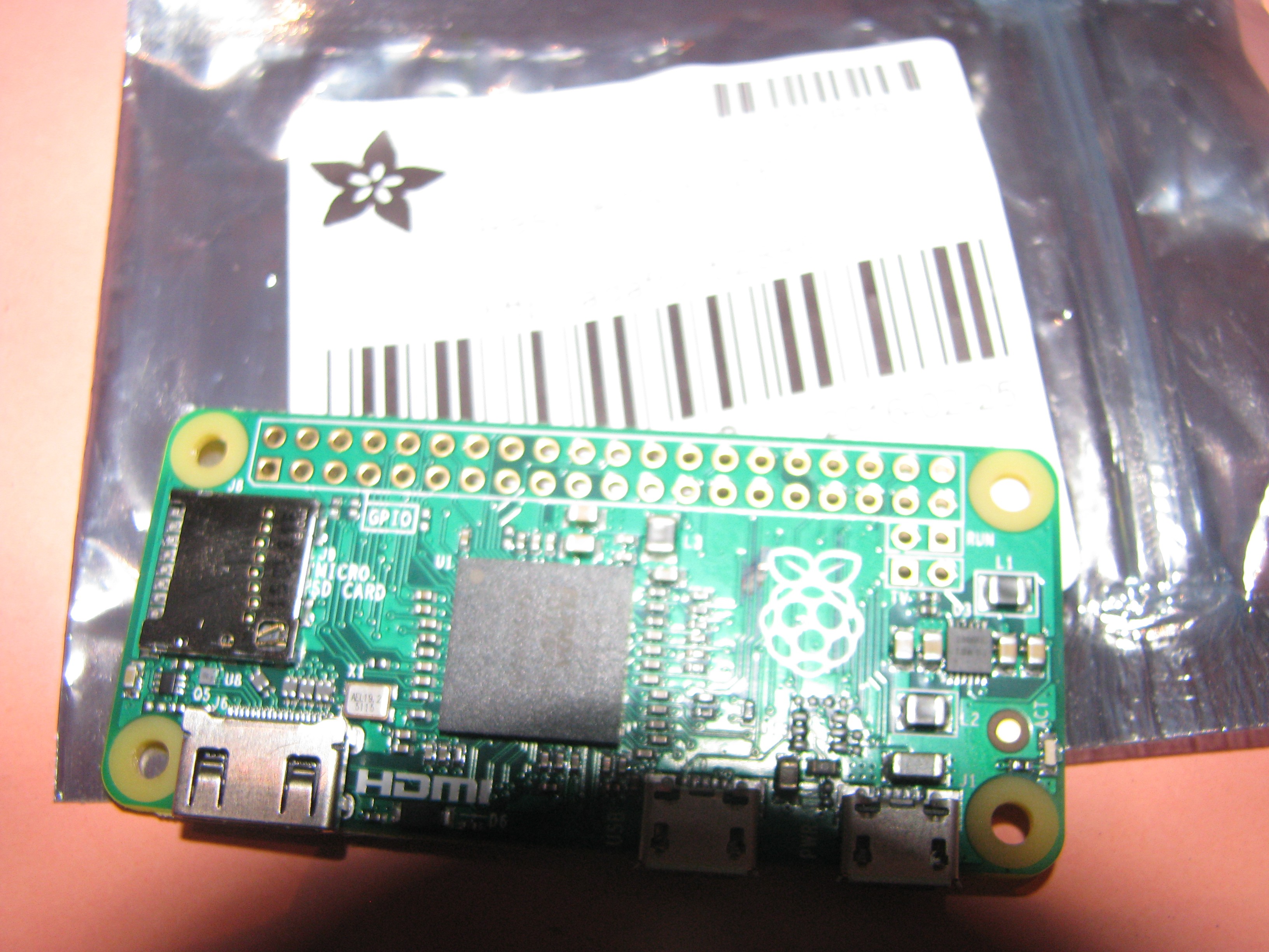
03/13/2016 at 23:59 • 0 commentsIt made it!
![]()
and looking on the back I was able to see that there are test points and i quickly wanted to know what they where. so i hoped on google and found some pages that gave info on what they where.
![]()
With pp1 and pp6 will allow power to the USB hub and pp22-23 will provide the D-D+ lines. Found this guide on google.
-
A little more...(because it is raining)
03/13/2016 at 00:03 • 0 commentsSince i got some free time due to rain, i decide to edit this a bit more. Now i have added the AC to DC power supply. I got some ideas from a breadboard power supply provided by Sparkfun. at the moment it is used as a 5v/3v but i am going to add a 15v Regulator to be able to provide a bit more power.
![]()
As you can see in the picture above i am using a transformer to bring down the voltage, at the moment to 5v/ then a rectifier to provide the 5vDC and then continues to the rest of the circuitry. I have added the SPI display and VU-meter modules, take a look.
![]() the vu module was "borrowed" from Jeff Thompson and his post "Simple VU Meter Circuit". The SPI display connect in the mid section of the picture above was made possible by following the tutorial over at Learn.Adafruit.com . and to right is the piZero Header that will allow the pizero to be connected to the "mainBoard".
the vu module was "borrowed" from Jeff Thompson and his post "Simple VU Meter Circuit". The SPI display connect in the mid section of the picture above was made possible by following the tutorial over at Learn.Adafruit.com . and to right is the piZero Header that will allow the pizero to be connected to the "mainBoard".![]()
I will adding the new schematic and board files soon. Oh almost forgot dont remember if i mentioned it but i have added a pitft3.5 "placeholder to help with aligning the roper connections".
-
Lets Add HDMI-AUDIO-MIDI and some other stuff
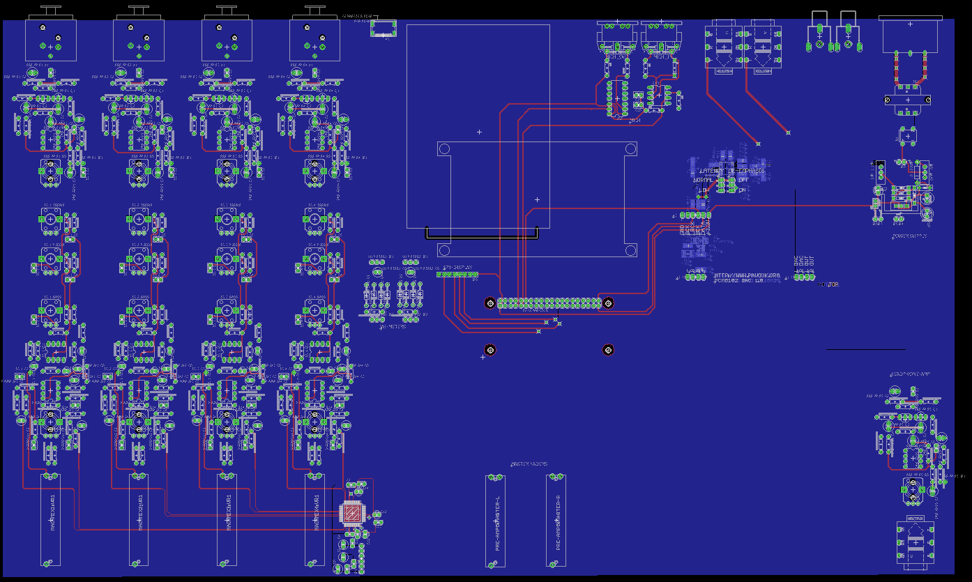
03/12/2016 at 07:06 • 0 commentsWell i got a little more closer...i have added a HDD placeholder so i can see where i need to place a couple of components. and HDMI port that will definitely be a Mini-to regular sized Hdmi Cable? Extension. i was going to try and make a on PCB routing feature but seems it will be easier to just use a cable and Hot-Glue it in place. I have added the midi Module from previous version and now is connected to pi0 Header.i order to get audio i will using the phatDac since it uses a PCM5102A. I have added the Monitor outputs, which wil be line outputs so to be used with external audio amplifier. I also have add a "Buffer" to the headphone output. At the moment the "Phat dac" was a version from PAVOUK.org ( check it out ). Still need to find out how i am going to power everything. need a PSU with 15v and 5V output. Next step is adding the tft display.
![]()
wanna check out the schematic? check it out here!
-
We have 4 Channels!
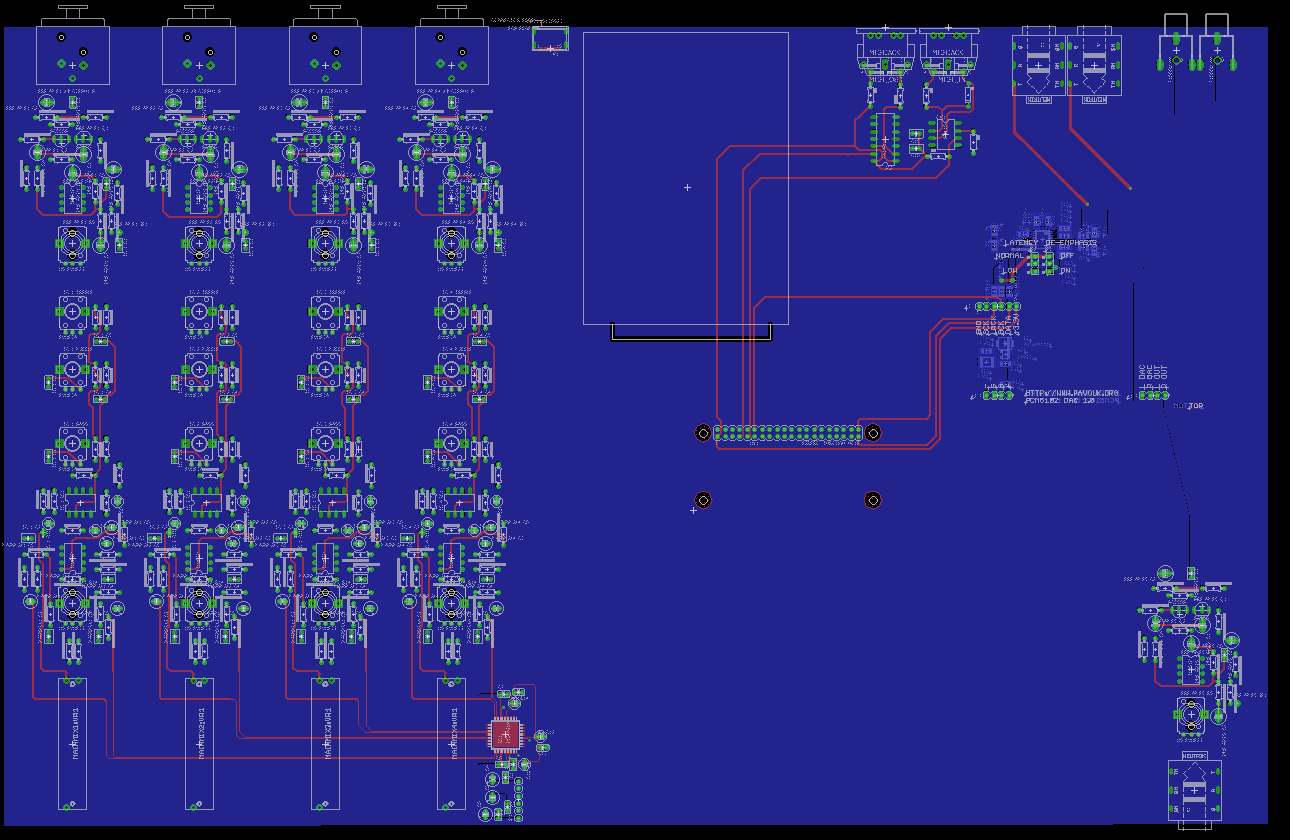
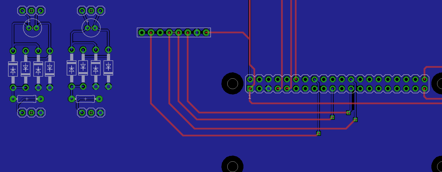
03/09/2016 at 07:19 • 0 commentsI have Finished laying out all 4 Channels and started adding the PCM4204 CHip that will interface with the piZero. Take a look!
![]()
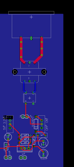
Also started to add the power connector at the Bottom...
![]()
Need to Make the signals that will connect to the piZero.
I need a quick brake...
-
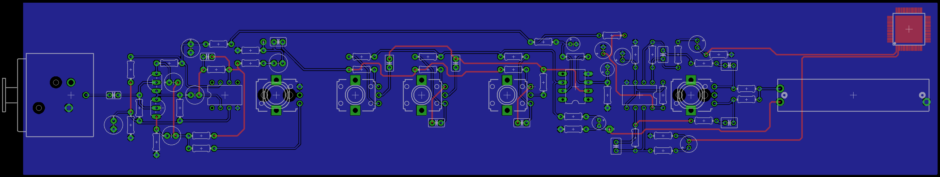
Ch.1 Done...for now.
03/09/2016 at 00:41 • 0 commentsWell i got it done. Now all the modules ( Audio Mixer ) have been finished now to do it 3 more times. take a look! also you will see the PCM4204 there for refrence.
![]()
After the next 3 get routed this section " Board " will be wired to the piZero.
-
Nice to be back.
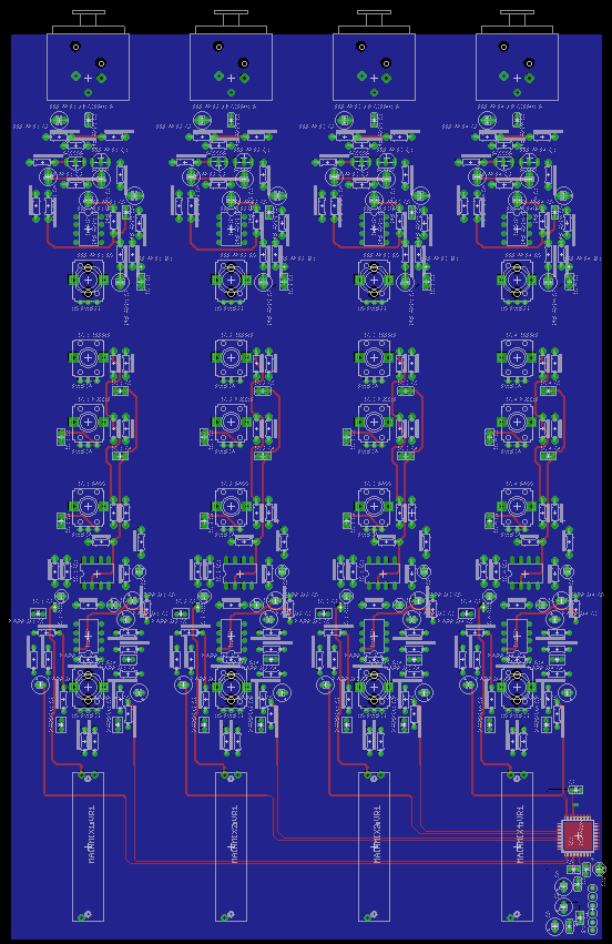
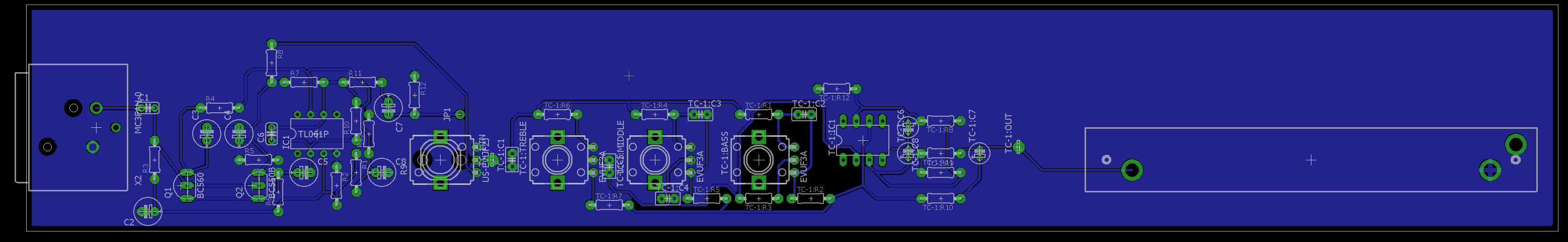
03/08/2016 at 06:04 • 0 commentsWell after a short leave, We are back at it! I have made "improvements" to the channel PCB, if you wanna look.
![]()
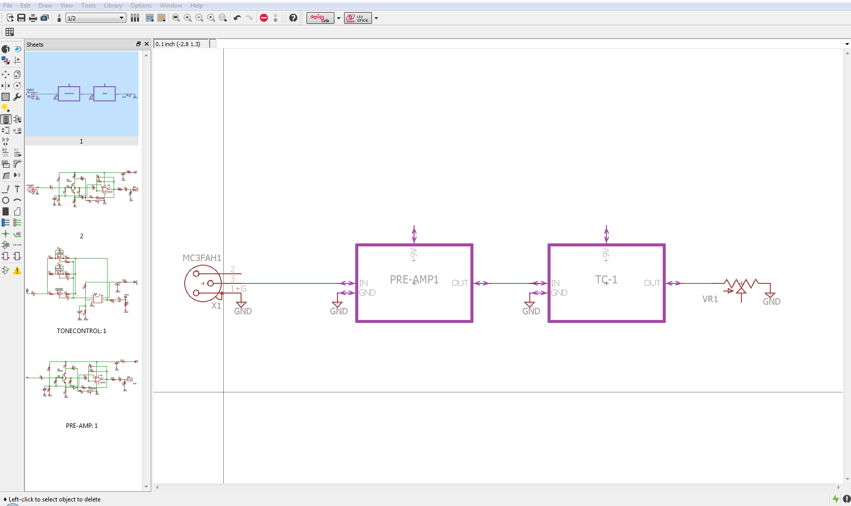
The final pcb will feature 4 of these channels. I have also Seperated the schematic into modules. Take a look.
![]()
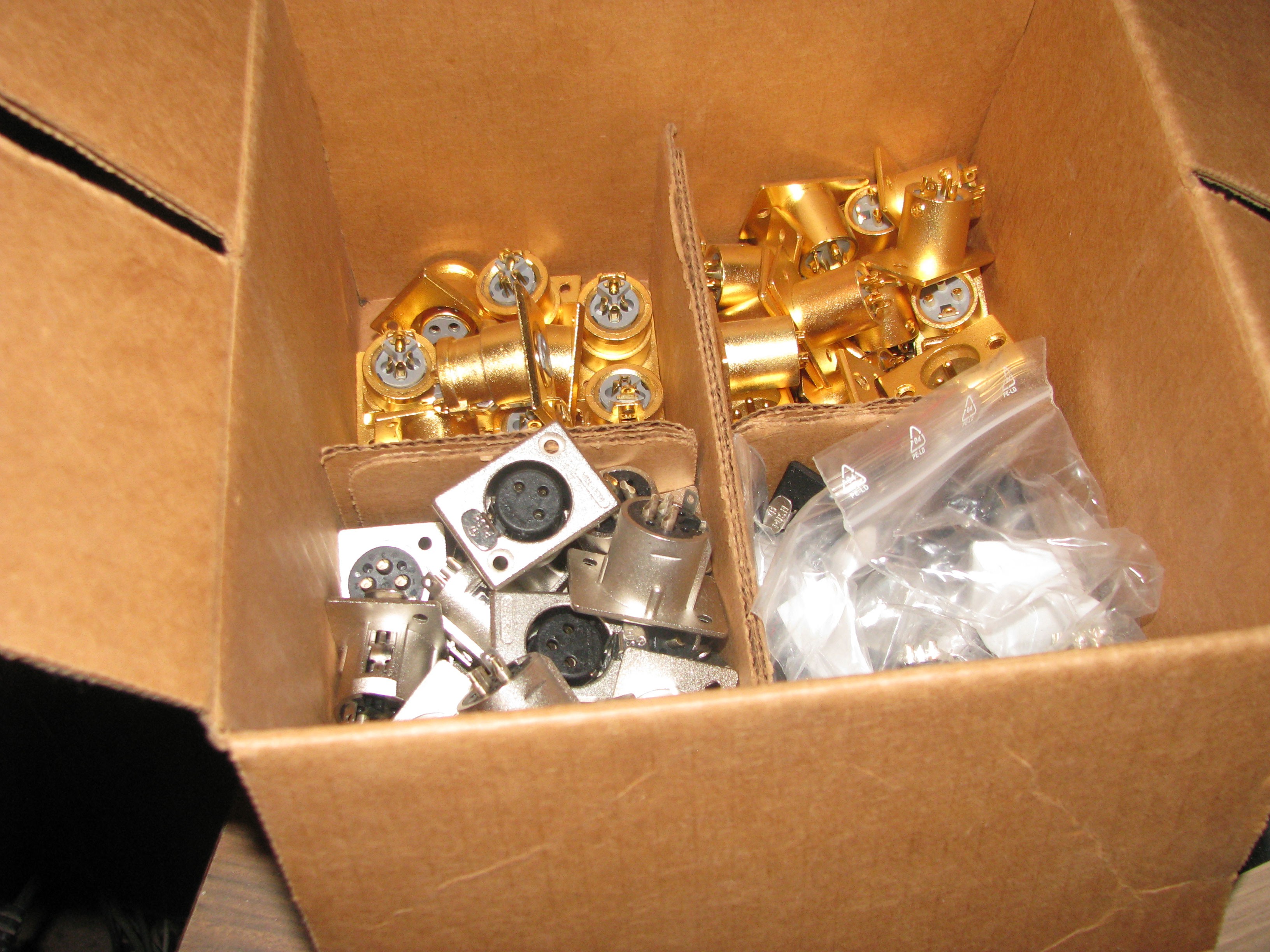
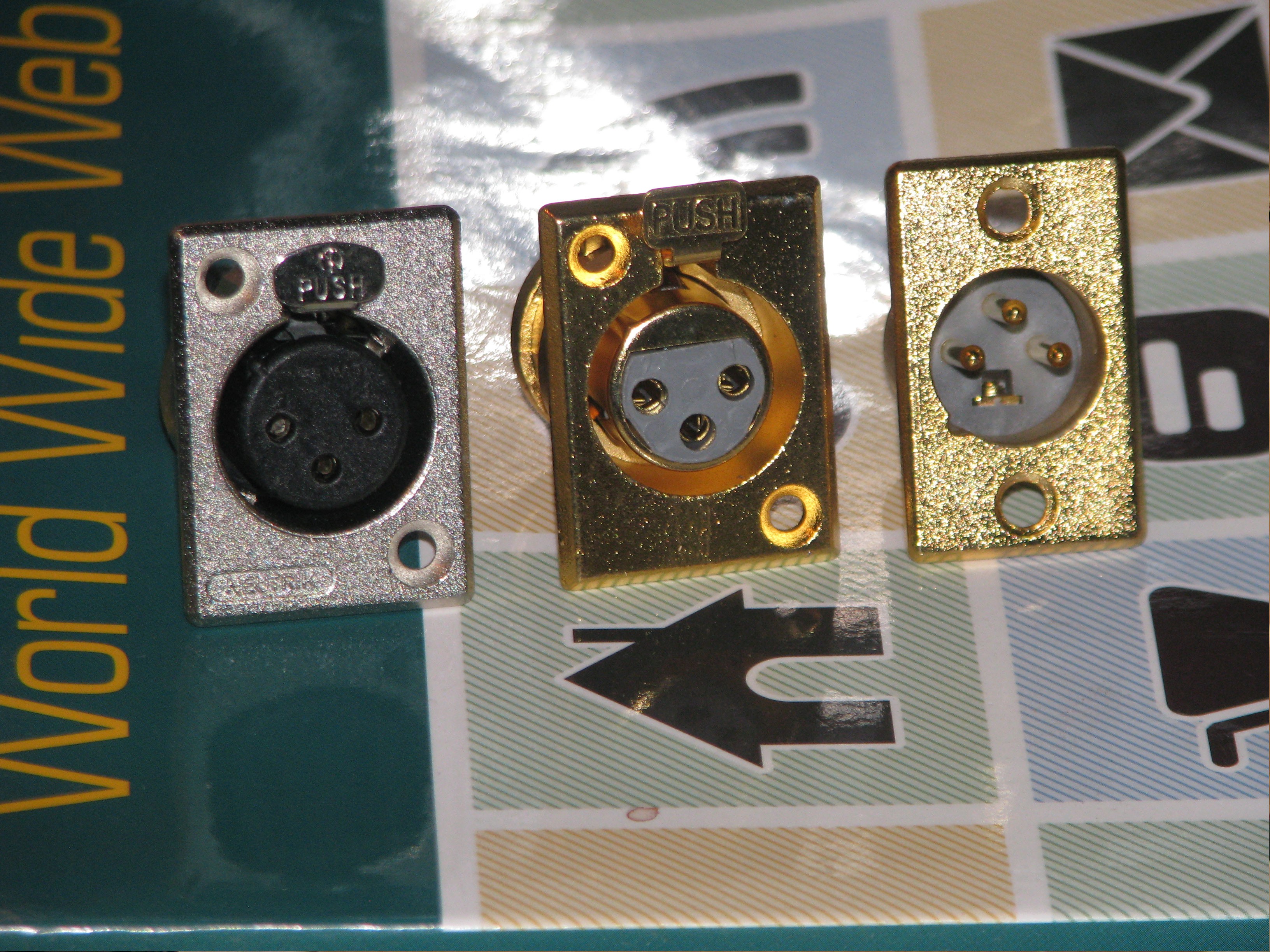
It is a nice feature that was pointed out to me recently. Also the XLR components Arrived while I was gone(took long enough!)
![]()
![]()
I will get back at it!
 If you want to check it out, the
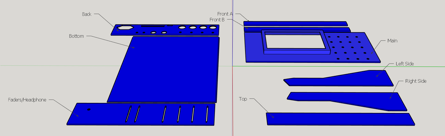

 the vu module was "borrowed" from