It all started while I was investigating why my complementary MOSFET oscillator wouldn't oscillate. Crawling around in the googlesphere, I found these pictures:
 (from Talking Electronics' excellent page about MOSFET)
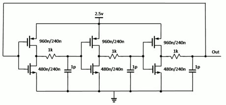
(from Wikipedia's page about Ring Oscillators and I wonder why the output is after the resistor...)
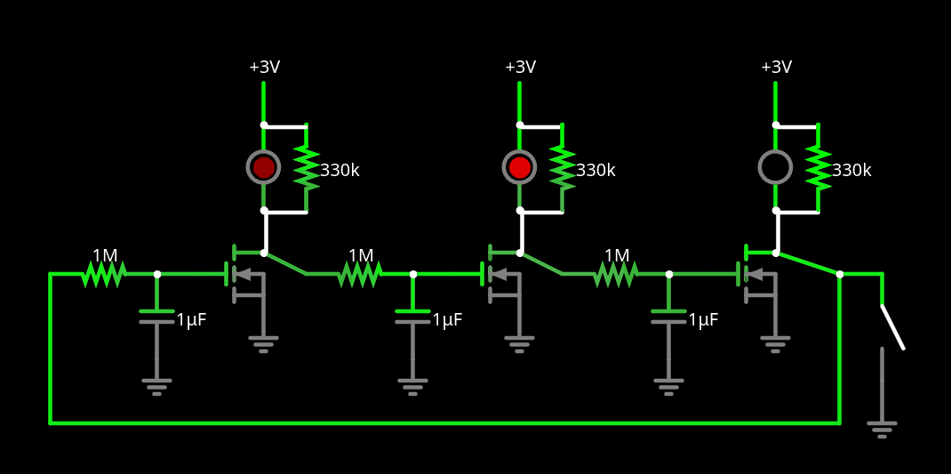
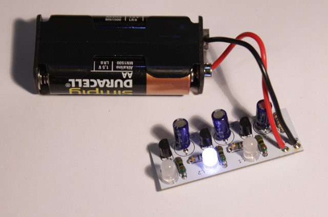
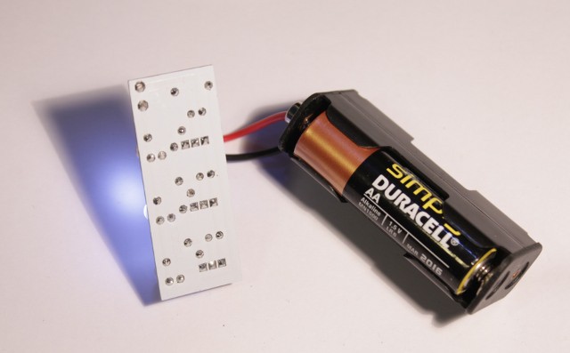
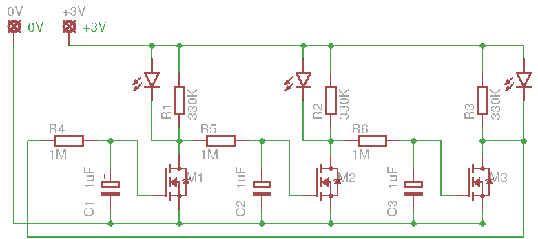
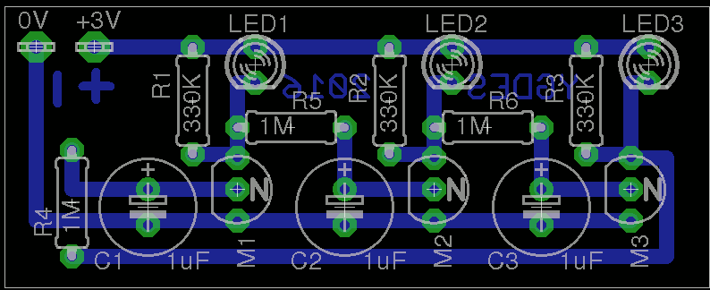
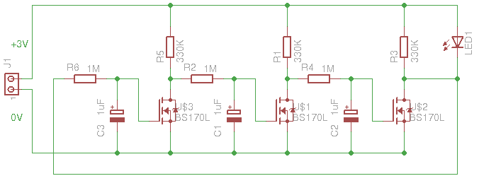
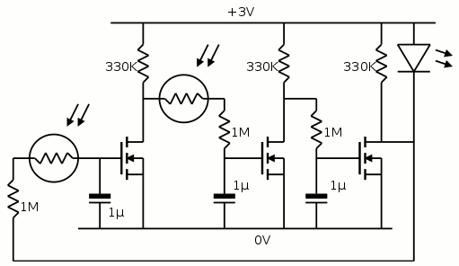
Let's just merge these two circuits, in a way that saves power and let's add a single, bright white LED (or yellow/green if you prefer, but I have white 1W modules) at the final stage (power LED are more energy efficient due to larger die, hence more light than normal LED when undervolted). Power it with a couple of AA batteries and you have a nice slow blinker.
How can we bring group synchronisation ? Add a light sensor. Well, that's a great way to use the batch of LDR (photoresistors) I bought on eBay. Add one LDR in series with one 1M resistor (at the right place) and voilà !
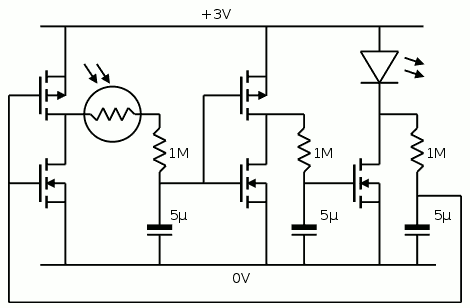
Warning ! the diagram above is flawed because it is missing a pull-up resistor in parallel with the LED
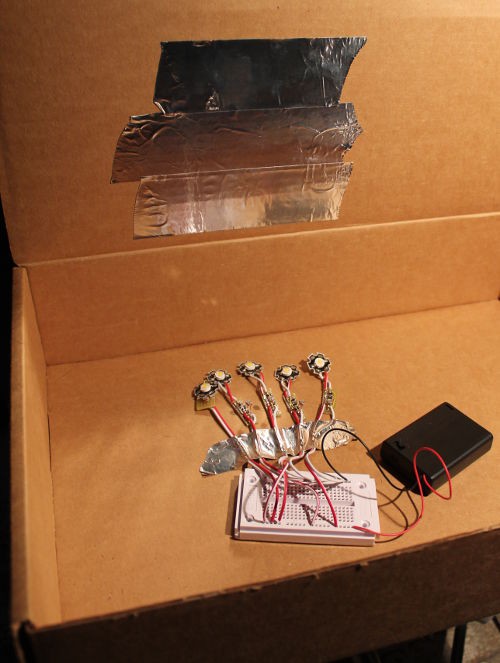
The LDR I have has a resistance higher than 2M Ohms when in the total dark, so a single ring will oscillate slowly. If it picks up some light from a nearby ring, the frequency will drift until it's in phase. 3 rings might give crazy chaotic patterns, but if more circuits interact, they'll finally go all in sync, like a clapping audience...
Logs:
1. First blink
2. Oscillation coupling
3. Coupled oscillations
4. Locking to bi-alternance
5. Family Fun !
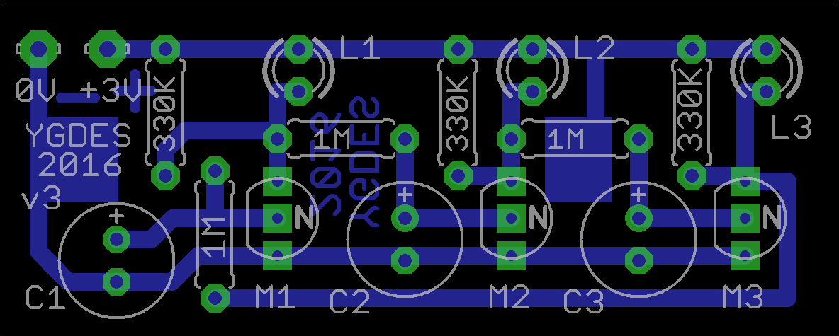
6. First layout
7. My first group course at LOREM
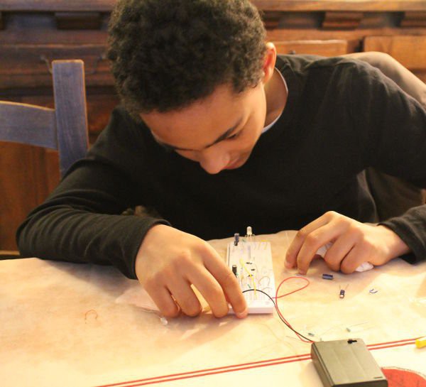
8. Today a boy made me feel proud
9. Board v2
10. Board v2 has been delivered
11. Board v.3
 Yann Guidon / YGDES




 Hulk
Hulk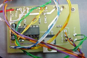
 Bruce Land
 Not Pike
 mattko
Hey Yan, heh, I was just looking at the circuit and made the connection between this and what I had a few years ago using 2N2222 transistors. Then I switched them out with LL for my sequencer :-)