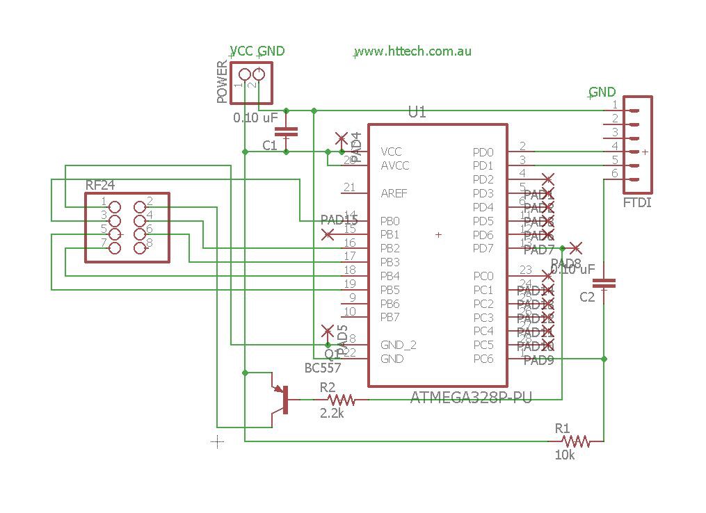
- The Arduino 328 chip has boot loader for ftdi & fuse settings to set low voltage protection to 1.8v & run at 8Mhz via the internal oscilator (avr programmer reuired.)
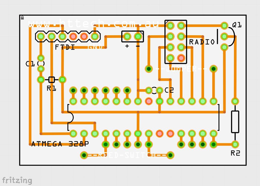
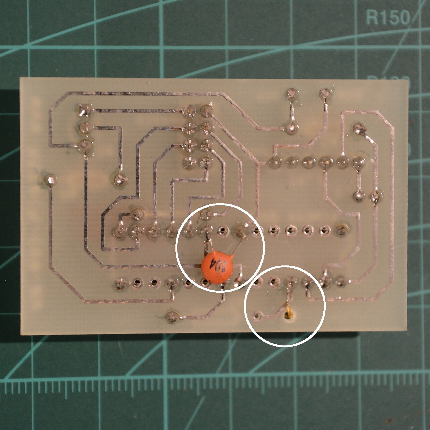
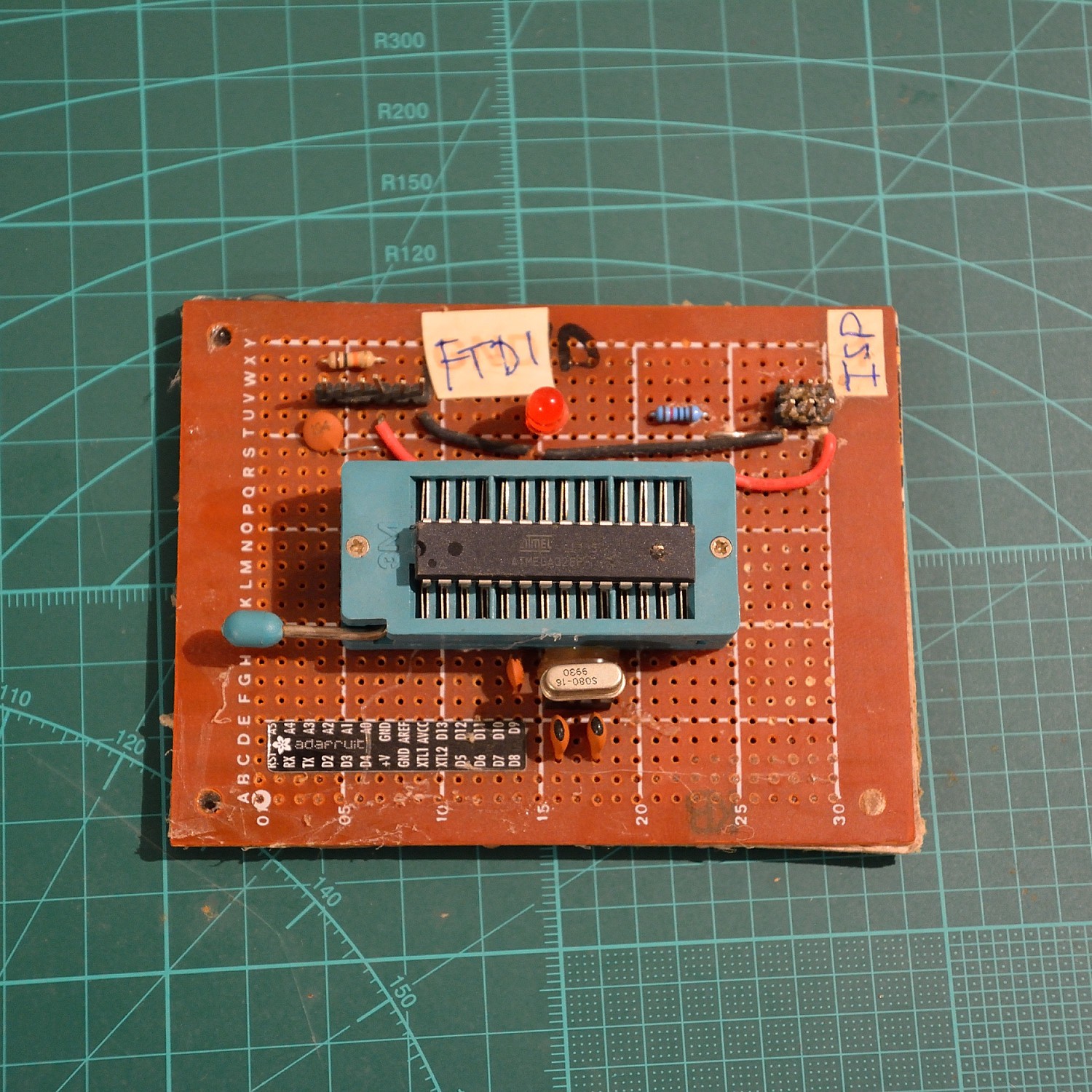
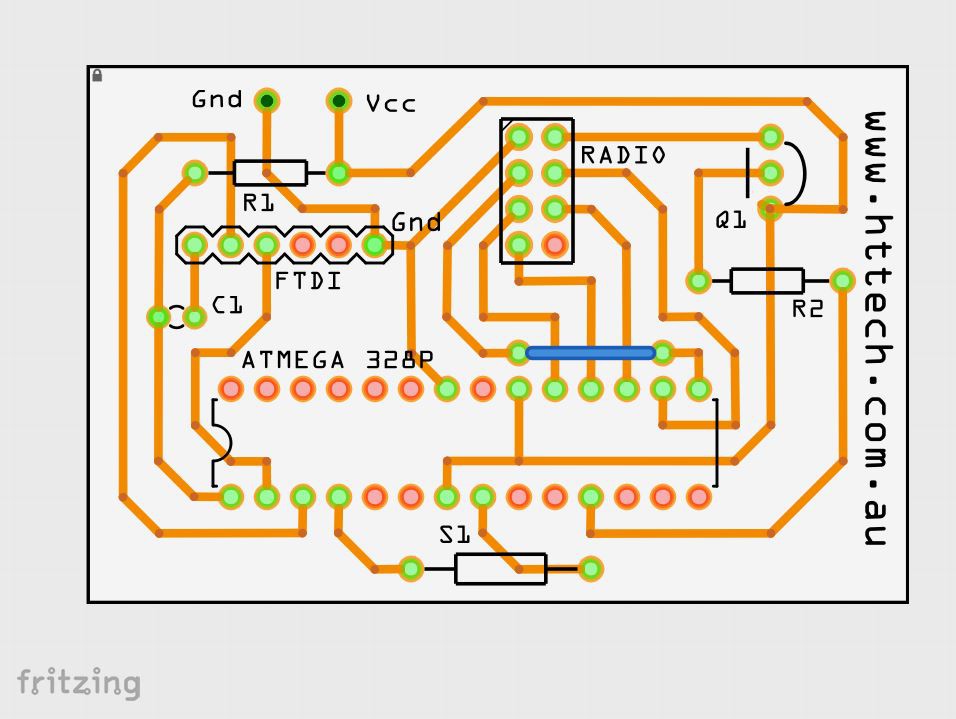
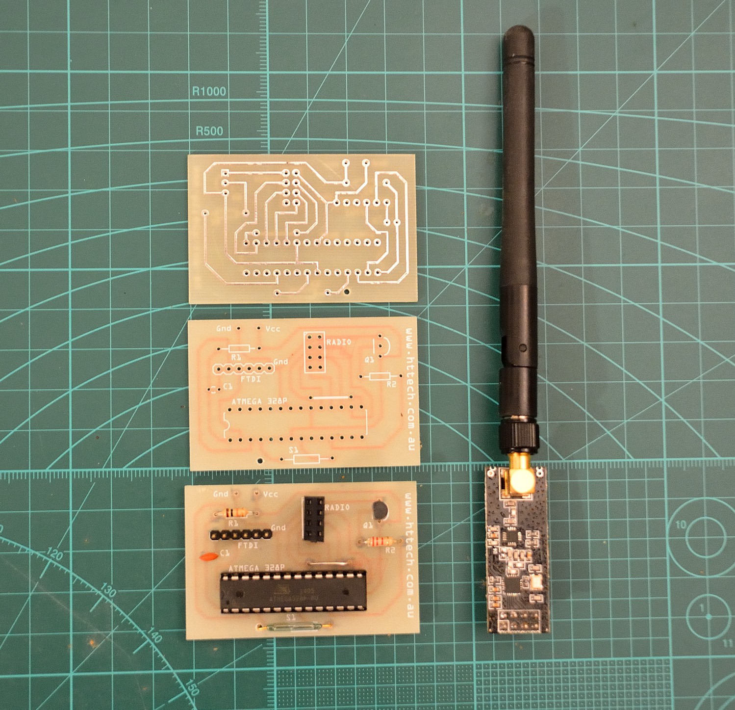
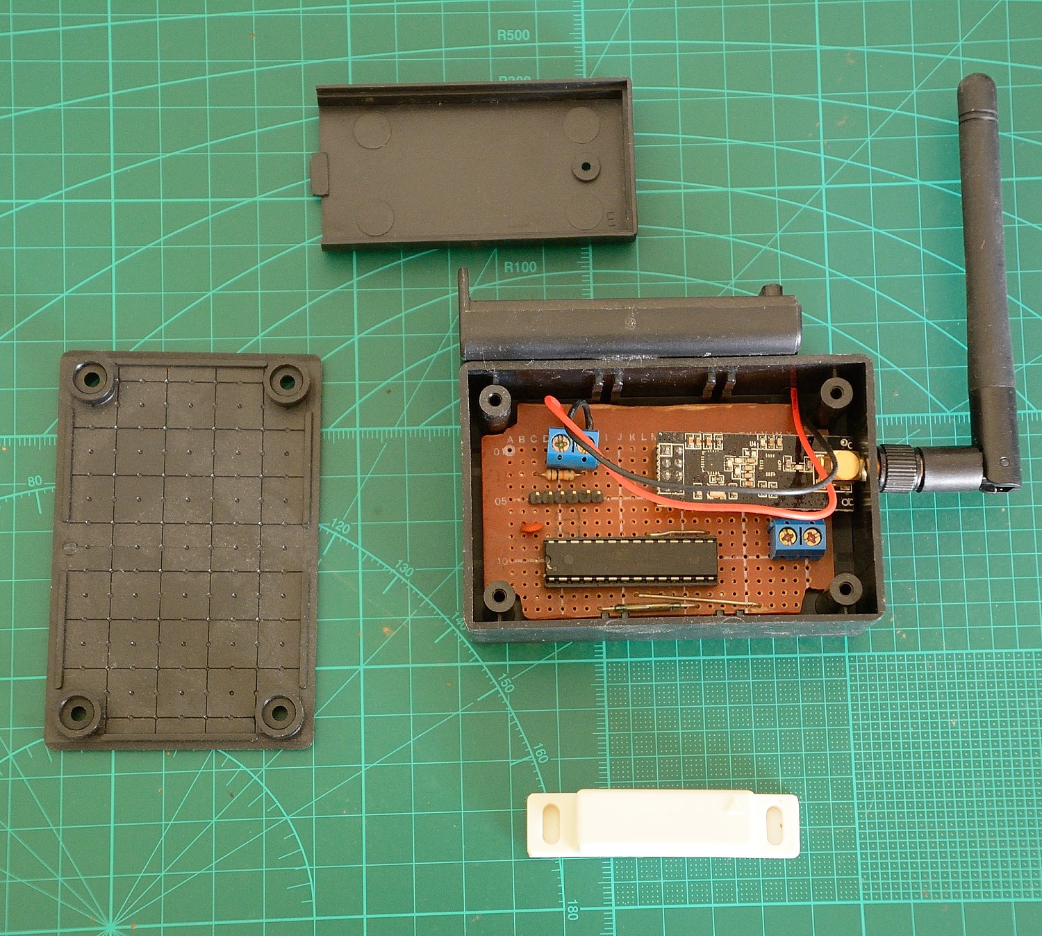
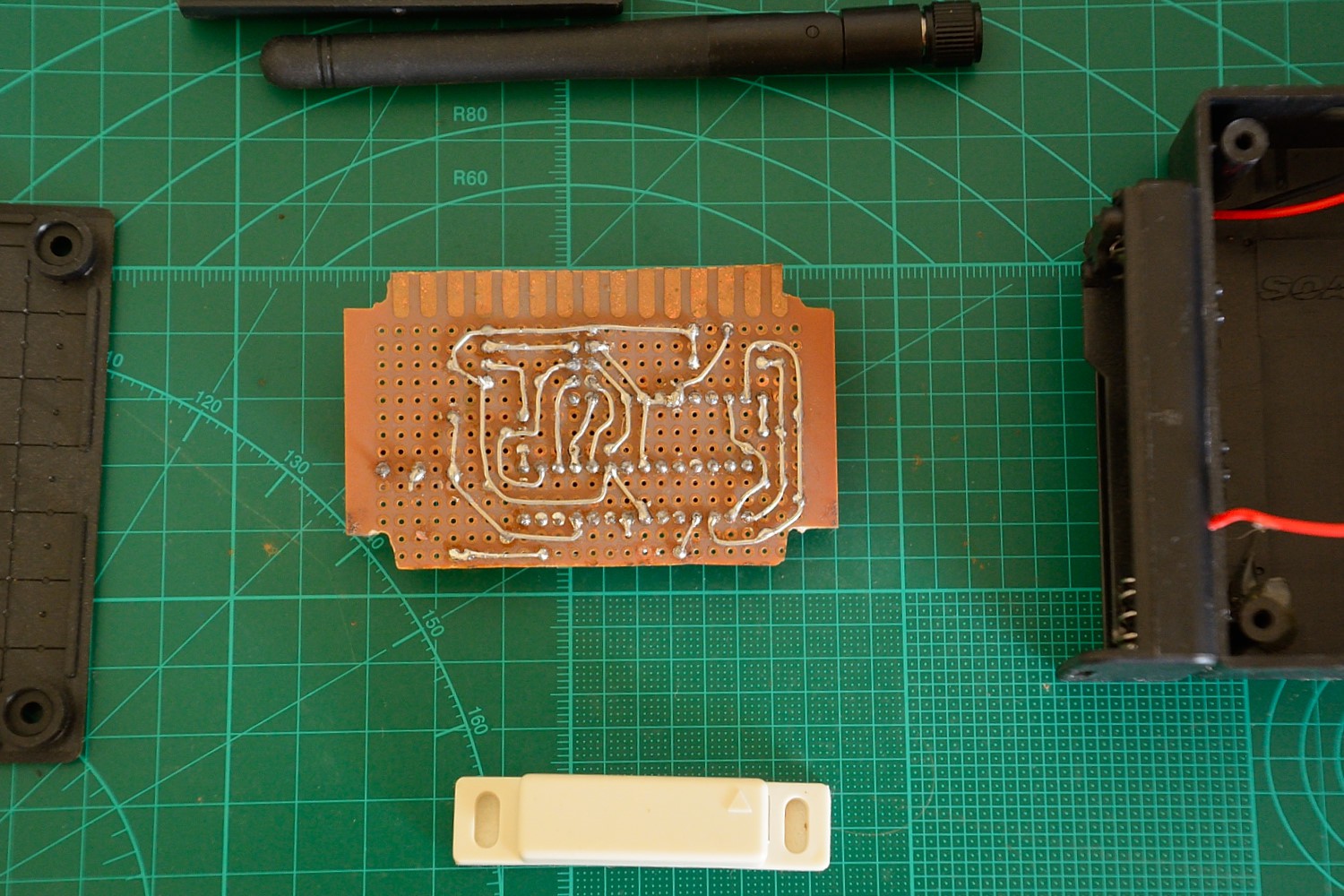
- Version 1 i have had produced and you see in the photos, this was my first pcb run, and there where a couple of minor problems, my reed switch had a wider whole spacing, and i needed to add a 100nF ceramic capacitor across the 328's vcc/gnd to smooth its voltage.
- Version 2 has some improvements, though i have not produced it.
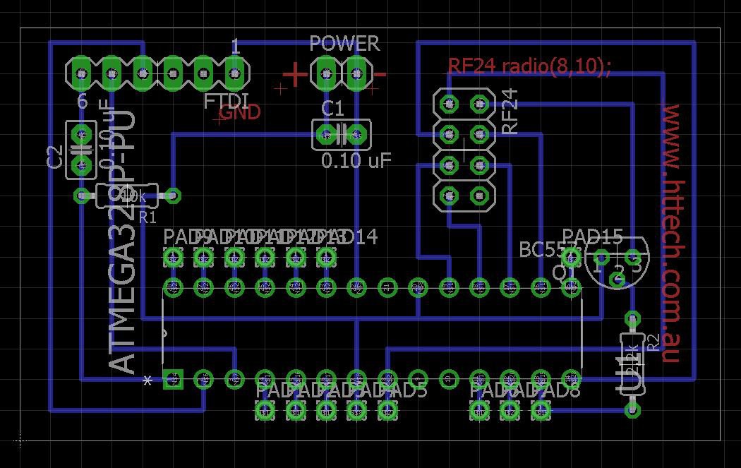
- Version 3 has been converted to Eagle, ive dropped the reed switch spot, relocated the rf24 switch transistor out from under the radio, and changed radio wires/routing to eliminate need for jumper.
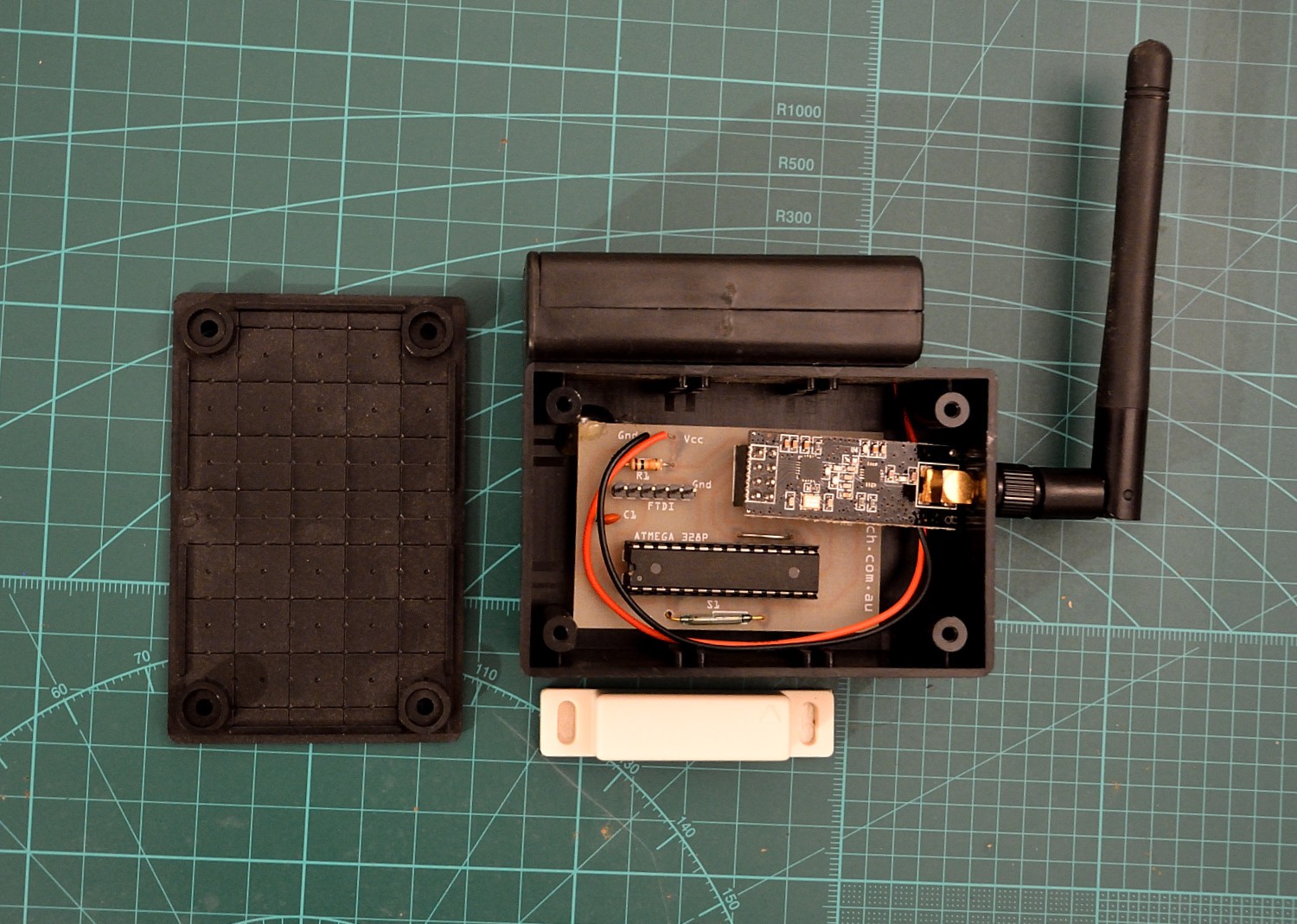
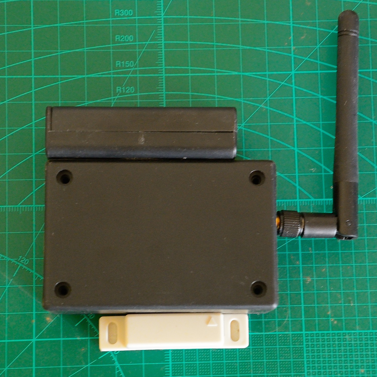
Single Layer Through Hole Arduino 328 & NRF24 PCB
Minimal, Long Range, Low Voltage, Long Life, with switchable RF Vcc
 hayden


 uhpowerup
 ElectroBoy
 Pedro Minatel
 Sagar 001
What method did you use to print the silk screen on PCB?