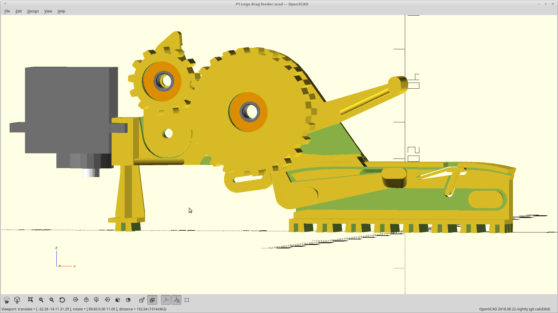
Got off on a tangent trying to make a new feeder using a pin drive.
It sucked, I scrapped it.
So, I stole some things from that design that actually worked, and updated this one.
Advances with vertical motion now, both cover tape removal and tape advancement happen on release, and now uses a pinch roller for cover tape removal.
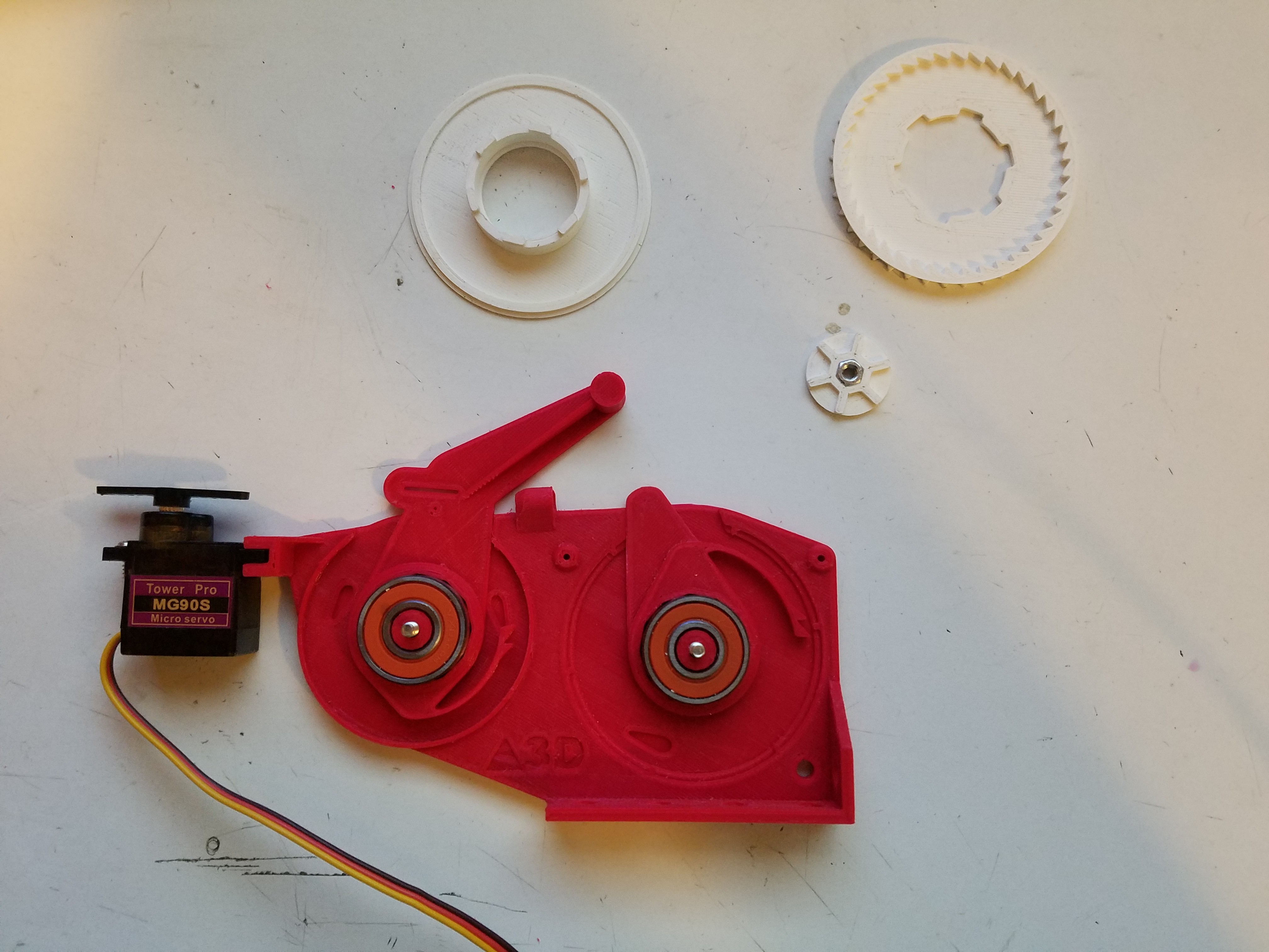
It also uses smaller 4x13x5mm bearings now so the whole thing is smaller and faster to print without giving up maximum part height.
I was also able to ditch the connecting rod in favor of integrated gearing between the drive ratchets, and I switched from a pen spring to using hair bands. The latter will be much easier to adjust the force required for feeding.
I was looking at how I was going to have to mount my tape feeders to the top of my build surface and not liking it at all. I was looking at an array of laser cut holes, a statically mounted DIN rail needing additional height, or some other nonsense.
Then this idea popped into my head and I went with it.
From henceforth when I say the word LEGO, please replace that with LEGO compatible.
Getting that out of the way, I've been a big fan of the building blocks since when they were cheap(er) and I firmly believe they are part of the reason I am who I am.
Ok... mushy flashback aside, I've found a logical use for them here.
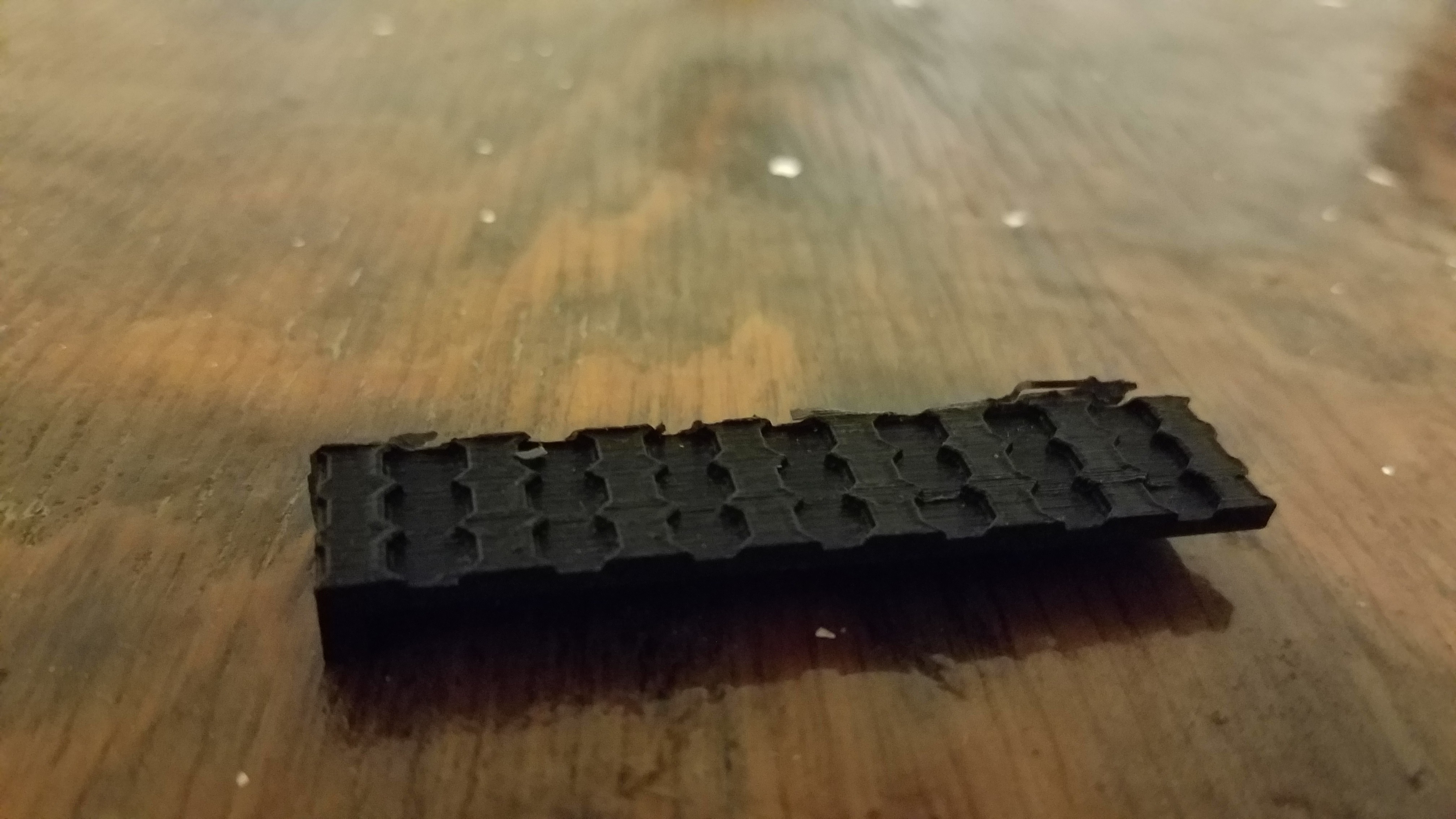
I wasn't liking the need to put holes all over my base to mount feeders. I went the laser cut route, then the DIN rail route, but then after a quick Google (yes, it's a verb now), I discovered that the dimensions of modern day LEGO blocks were exactly 8mm spacing between 'pins'.
This prompted a current quest to make a half spacing LEGO mount, so I can have 4mm spacing, which will give me the ideal mount for my feeders given any width.
Iterating on this, until it is a perfect fit, then it will go under my feeder.
Third try, getting close.
EDIT: Not close enough. After much iteration, I've determined that the tolerance required for the interference fit I designed here is less than 0.05mm.
That is bound to generate significant amounts of swearing, on a 3 hour print.
I think I really need to redesign this to be a bending interface instead, like actual LEGO parts.
That still would be really hard to do as a side wall, so I think I'm going to split this into its own part and print it vertically for attachment to my feeder later.
I'll do that and print it while I'm sorting out the RC servo PWM code tomorrow.
I need to move the cover tape slot back and turn the cover tape pull distance up a bit.
The latter will change a good number of dimensions. Hold off on printing for now.
I'll have the updated files up by Saturday.
EDIT: I took one to the local Makerspace and Sim had a mounting suggestion which I really liked.
I'm adding a DIN rail mount to the bottom. It was also 'sticky' after my changes.
I'm not done with it, and currently busy with the P1. I'll get back to this when I'm ready to mount one.
EDIT 2: I had a bit of a eureka moment this evening, and I'm changing the mounting again. I'll keep the old bolt-down one for those who don't want to go in the direction I'm heading, but I personally can't wait to try it.
I'll give you a hint. Lego's have 8mm pin spacing.
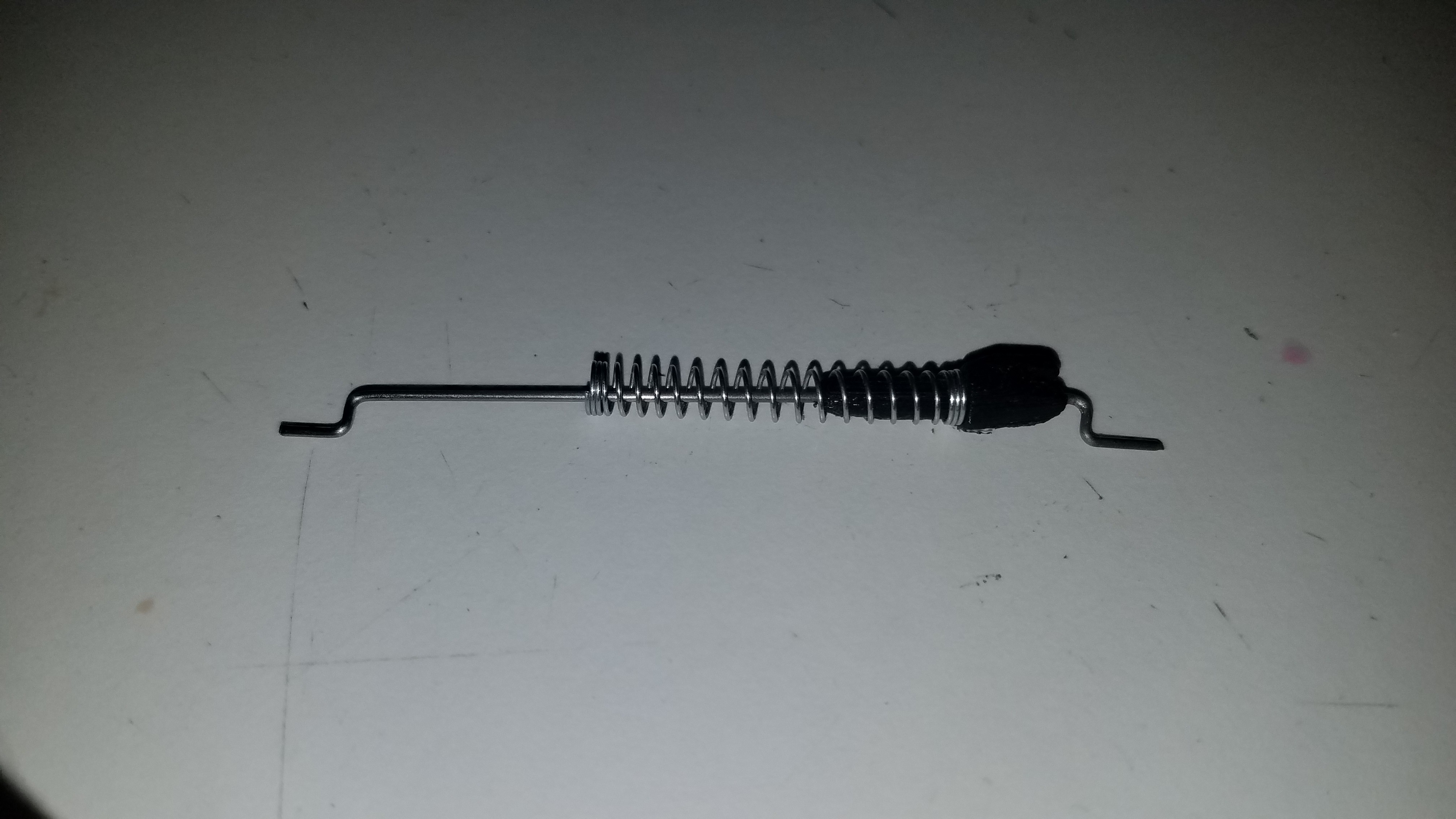
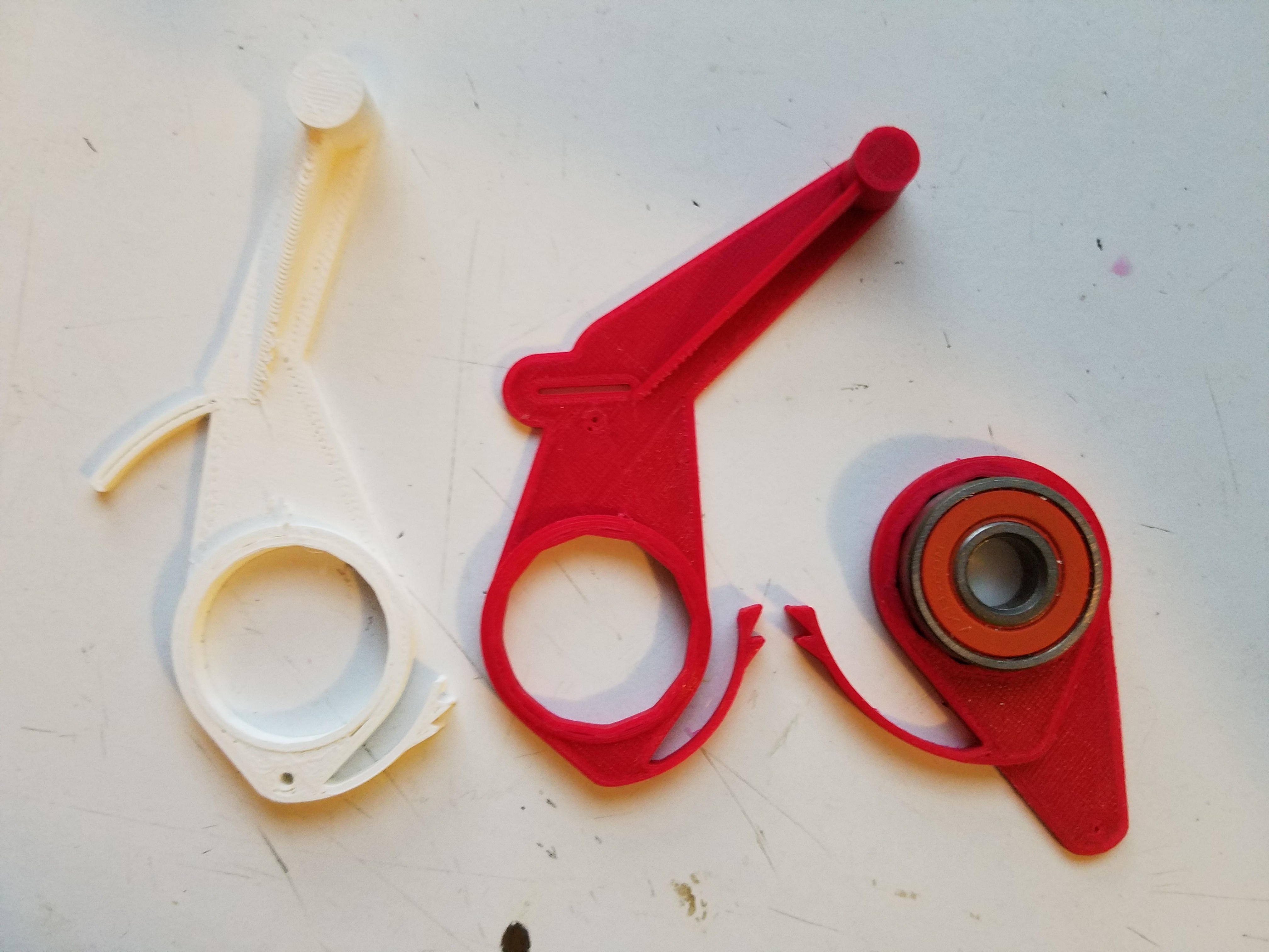
I made a little throw-away template you can use for bending the connecting rod/getting the connecting rod length and the pivot depth 'correct' more easily.
Here is what the connecting rod should look like when done, and fit the length of the connecting rod template holes.
Oh... and don't forget to put the spring pivot part on the rod before bending the second end. It's rather impossible to get it on after bending..
I've also discovered it is much easier to make the first bend at a 90 degree angle to where it's supposed to end up, so you can get the perfect depth for the pivot points and then rotate the resulting end back to straight. I'll post a video later.
The connecting rod template is in the source now, and rendered as a part on Github.
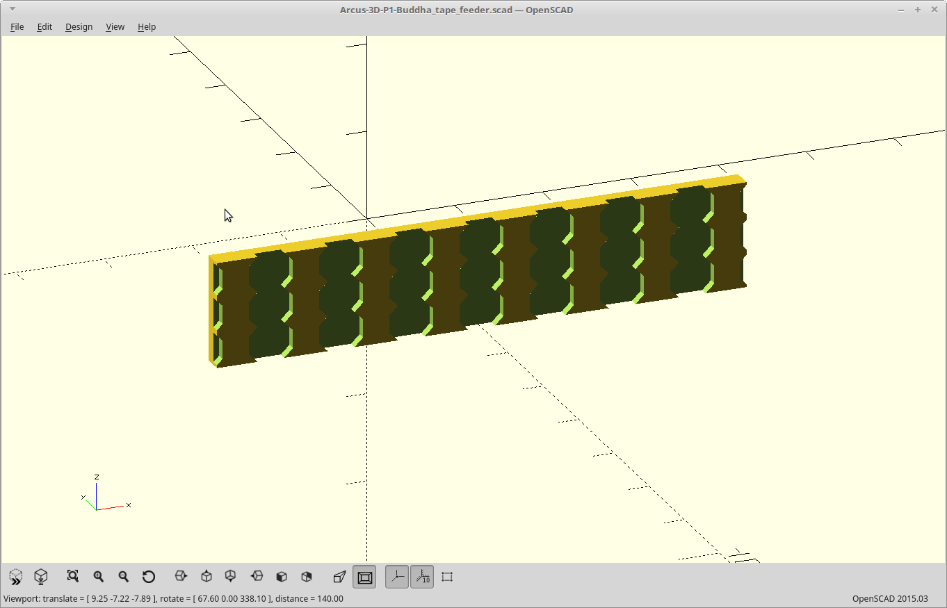
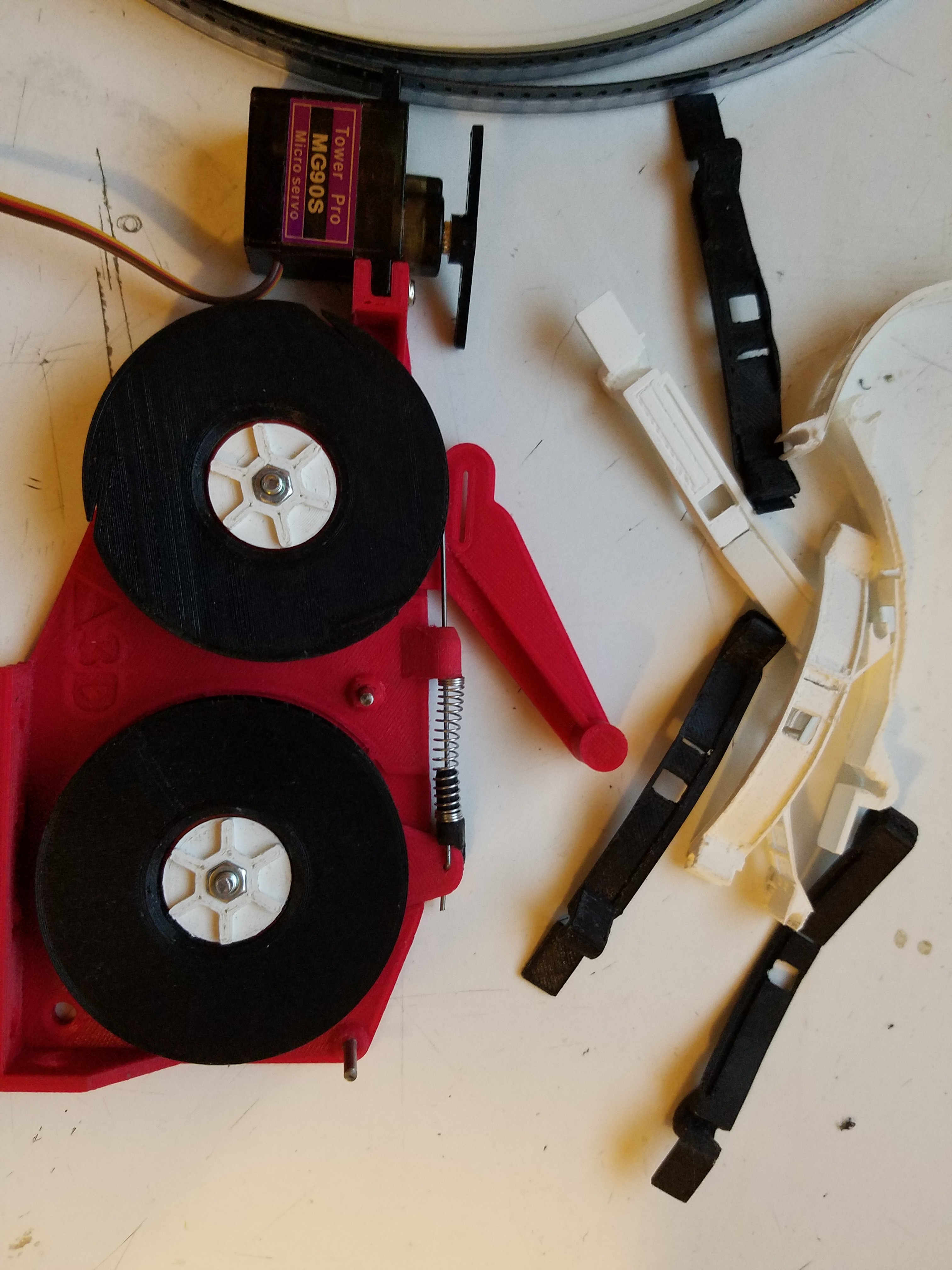
After about 20 different versions, I've finally honed the tape cover to a point I'm satisfied with it.
It bends eventy, and just the right amount, despite having two big missing bits nearly across it. That was a lot harder than I thought it would be...
Three reasons I put so much time into this:
Since it's printed flat,, it's the bottom, aka.. perfectly flat/smooth surface, that is riding against the tape.
This is the only component which experiences sliding of the tape, and so the only component you should have to replace. I wanted it to be small and removable.
You can adjust the dimensions of the hole the part is picked from so as to reduce the tendency of parts jumping out before they are picked. Aka, use a custom cover for each part if you like.
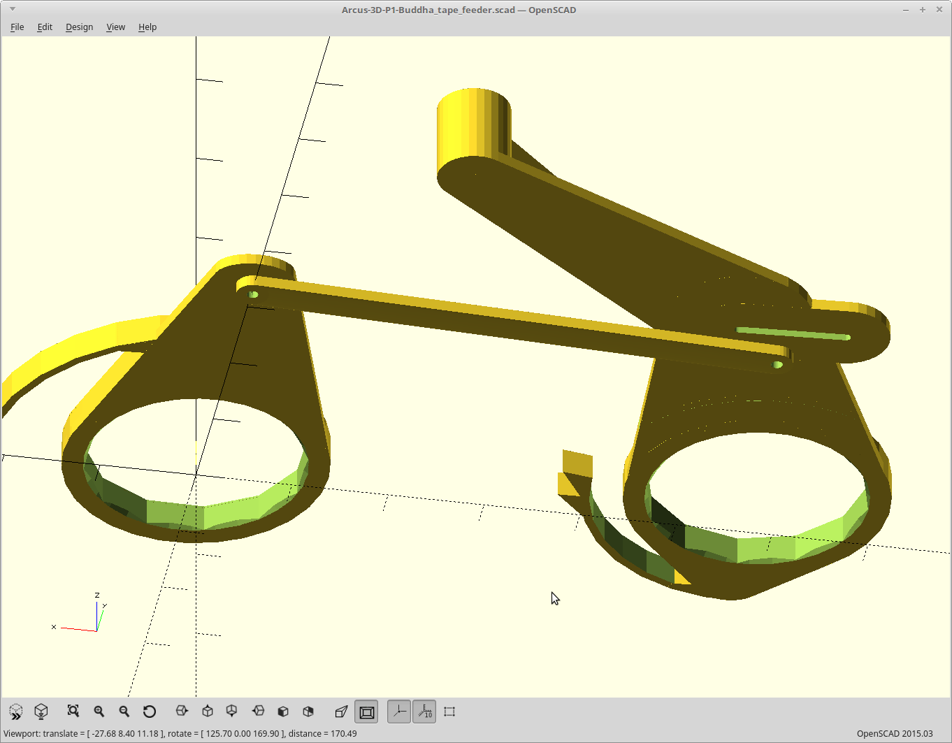
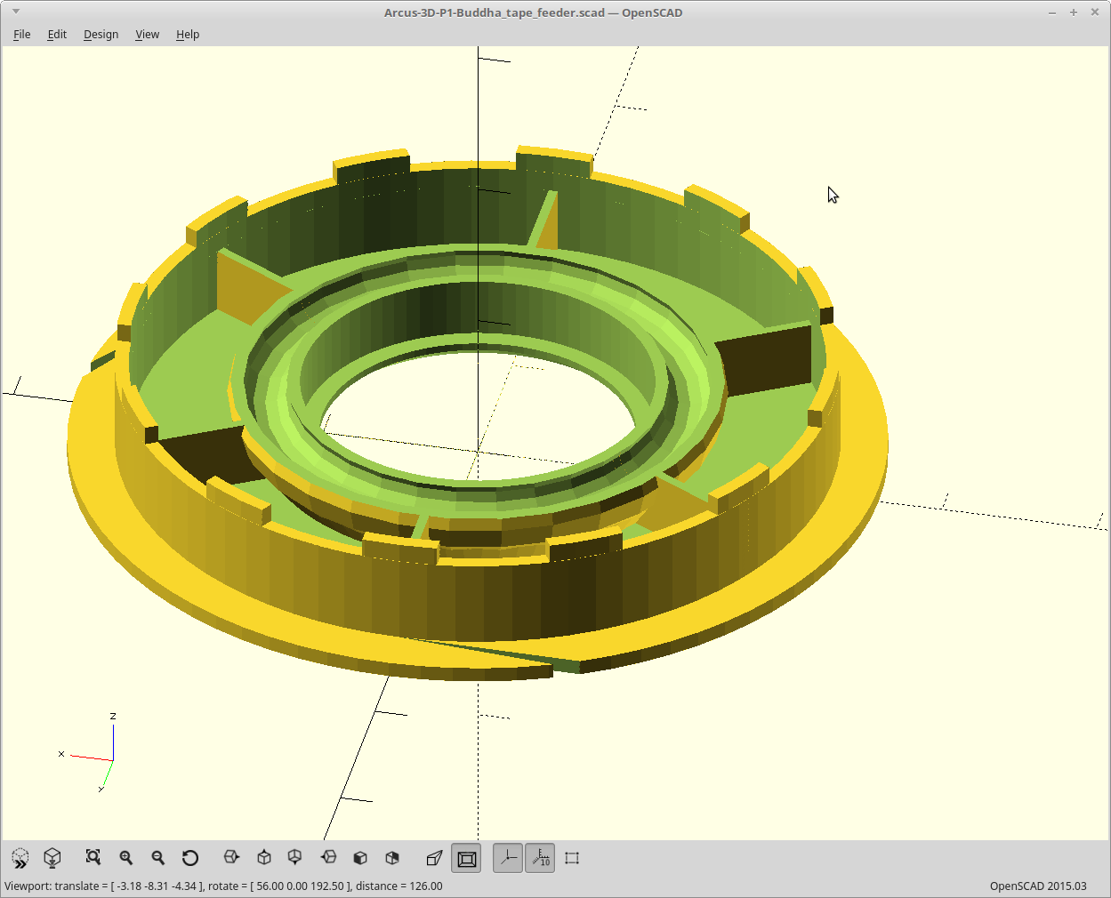
So without further ado... here is the finished product and my video with rambling explanation.
Still dialing the tape cover in. I've found out it's rather hard to design a bendy thingy with two holes spanning nearly across the middle of it, and one hole that goes all the way to an edge.
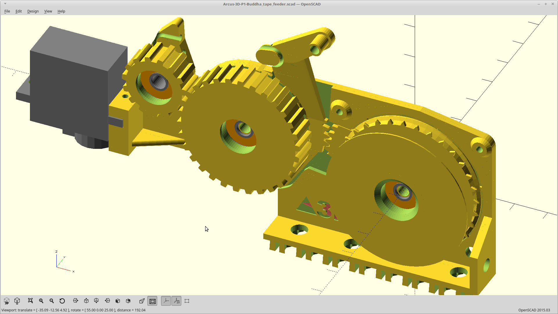
Everything else is sorted. The tori solution for cover tape tension adjustment is good, ratchets are tuned and working perfectly, and moving the spring to the connecting rod and moving it up top worked great.
Moved the return spring to be coaxial with the connecting rod, and reworked everything around that. No more bridging required for the tape_drive ratchet. Where it connects to the connecting rod is a bit thin now. It's strong enough for sure, but long term wear may be an issue. I left it that way as the top surface lines up perfectly with the center of my spring mount which can be flush with the bed, and also the matched top surface of the lever arm then. That means the connecting rod is a straight bit of wire under tension. Easy is better, probably.
Moved the servo down a bit to line up with my slot for driving it and added a second set of mounting holes for sharing a servo between two feeders. The slot drive makes this possible. You engage a feeder by pulling, pushing just slides in the slot so both servo connections can be 'simple'.
I broke out the signature filament as I think this may be 'the one'.
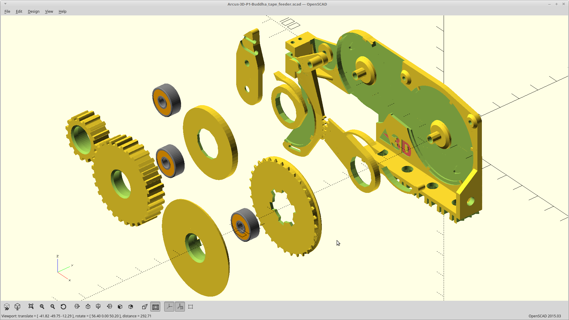
I also added 0.2mm of clearance to the ratchet teeth/ratchets so they engage a tiny bit better, and changed the ratchet spring length so it is now a function of tooth count and not an angular percentage.
Having the spring length be an angular percentage meant that larger diameters got longer arms, but the 'springiness' was constant due to the arms being exactly 2*<nozzle_dia> in thickness. So the ratchets for the smaller diameter cover tape spool were a bit too clicky, and the tape drive sprocket was not clicky enough. Using tooth count instead solved this nicely.
Of course this means reprinting nearly everything as changing the ratchet arm length changes the pin mounting holes, the sprockets, the drive ratchets, and the pin ratchets. Basically everything but the tape idler spool.
The useable range of the clutch was too small, and worse, it happened while the tension nut was way too loose.
Cover tape tension varied from good enough when just barely touching, to way too much torque, at just 1/4 turn more of the tension nut.
I modified the cover tape idler so the clutch slot is now two tori with both slightly askew, so the O-ring should have two high spots which engage first. I also reduced the spring tension on the O-ring as much as I could by putting it back on the bearing directly.
I also took a trip to Walmart to scavenge some more pen springs. Eight clicky pens for like $1, but the springs are stronger, longer, and worst of all, they don't like to stay in-line when compressed like the one I had before. I'll need to plan for sucky springs I think, so I'm modifying the design so the spring is coaxial on the connecting rod.
Moving the connecting rod will be a good deal of work though.
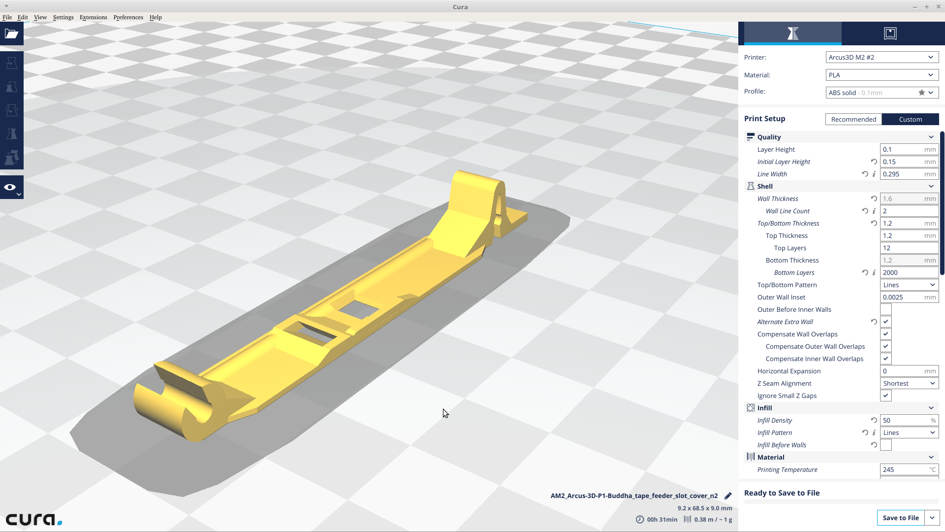
In the meantime I've been iterating on the slot cover, trying out different bending amounts lengths, etc. Don't have a perfect one yet.
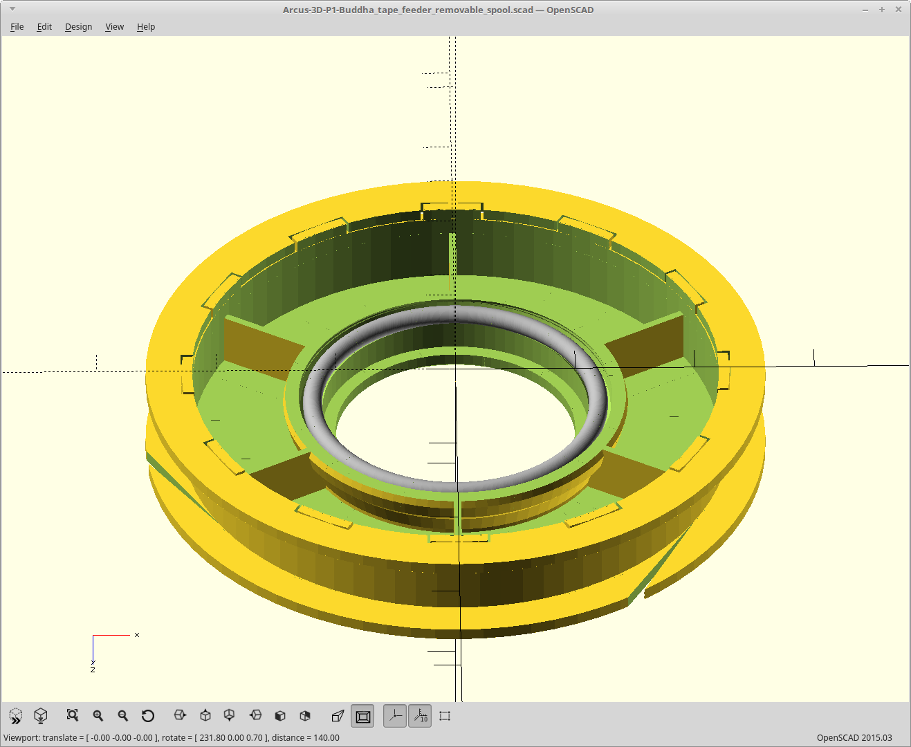
Revised the clutch so the cover idler gets more meat on the bearing. It needs to be a press fit as the hub pulling down on it is what provides the clutch pressure.
Advantage in that now it's completely obvious where the O-ring goes, disadvantage in that now you have to use the right size. Before it could handle a pretty wide range of thicknesses as it was a wedge.
 MasterOfNull