 CapitanVeshdoki
-
electromagnet /something/
05/10/2019 at 16:47 • 0 commentsAs almost everything was done with electronics,
(v1.2 control circuit PCB's are on their way)
it's time to think about structural questions.
And first one - electromagnets.If we even can control them efficiently, it doesn't mean, that we solved problem of energy density, which defines how much force we can get from the electromagnet within some weight and size.
There are some things which I discovered recently:
- according to precious Coil64 (big thanx to developers, very useful software), with limited voltage best way to improve pulling force - is to use wire diameter as big as possible, however, too much current would generate big energy loss on semiconductors, so it's a questionable decision. Control circuit has a way to regulate amount of energy being pushed into coil during a cycle, so it might be a solution. Also, smaller capacity on C3 means significant rise of voltage (comparing to a supply voltage)
- cores with great permeability are wild! They can increase inductance (read as "top energy of magnetic field for a specific current") very much. I don't know where to find Metglas cores with needed dimensions, seems to be impossible now, but I've bought induction heater to produce "very-pure" iron, annealed in hydrogen. Permeability of such iron is very close to Metglas and it's possible to fabricate for yourself (of course - you need to be careful)
Combination of a great core material and control method should do the job, maybe I'll come up with additional ideas about increasing energy density later
A concept how it might look, with coilformers, cores e.t.c ->![]() Fe cores are grey there, main reason why you can see them - nothing is between coil and core on sides (only electrical insulation), minimizing gap between wires and core is a crucial thing, as it defines inductance pretty much!
Fe cores are grey there, main reason why you can see them - nothing is between coil and core on sides (only electrical insulation), minimizing gap between wires and core is a crucial thing, as it defines inductance pretty much!
Stripes there are glued to the deep-purple parts, their main task is to transfer tension from the stripe to bearing at the back of electromagnet. If you need to swap stripe - then you should unscrew deep-purple parts, electromagnets untouched.
So,
Now I have:
- 2x stripes
- control circuit (previous version)
And one thing I miss to get the thing done - cores. Hopefully, I would find some material for them on Sunday.
P.S. I'm pretty curious about energy dissipation, because I can hardly feel heat from electromagnet with which I tested control circuit previously. It would be quite surprising to find out, what it's not heating at all. Quite strange. -
Control circuit V1.2
05/06/2019 at 21:07 • 0 commentsHooray! I've managed to simplify circuit even more!
Choose of electric components is more reasonable now - main MOSFET in D2PAK package and stabilizer for 5V logic voltage in small DPAK package, as logic gates never consume too much.
Here is how new schematics looks:![]() New:
New:
- one transistor instead of two
- low-pass filters on inputs, it can use PWM output from a MCU
- as well, filters are helpful to suppress high-frequency noise
Still, it has all experimenting stuff - V_TRG isn't connected to BAT+, so it's possible to play with it (or place wire between them) and still there is a possibility to try another approaches to measuring current with help of jumper JP1.
PCB![]() Around 5x5cm now, with mounting holes
Around 5x5cm now, with mounting holes
Now it's time to fabricate it and check everything, but I'm pretty sure what it should work, because previous version worked as needed:![]() And there is only one major change in schematics (of course, previously there were two transistors, but anyway, C3 is connected to ground on last PCB and D2 was connected to ground in experiments manually by wiring, while I was working onto question how to read current on electromagnet properly),
And there is only one major change in schematics (of course, previously there were two transistors, but anyway, C3 is connected to ground on last PCB and D2 was connected to ground in experiments manually by wiring, while I was working onto question how to read current on electromagnet properly),
I've thought about flow of electrons here for some time and I can't find any flaws in new design, happily :) -
/Thoughts/
05/03/2019 at 14:51 • 0 commentsLast two days I've spent in nature's lap, now I'm ready to think about ongoing things to do.
First of all I measured energy retaining rate more precisely:
- blue channel is voltage on gates of FETs
- yellow channel represents current on electromagnet, as always![]() - typical current here must be around 108mA (10V, 40% duty cycle avg.)
- typical current here must be around 108mA (10V, 40% duty cycle avg.)
- we have 20.7mA
- 5.3mA is a consumption of a stabilization circuit and logic gates
- so, we can assume what electromagnets consumes 15.4mA
Result: approximately 86% energy retained!
All is great with that, but one problem is still there - noise. An it isn't a noise from switching circuit, experiment shows, that it depends on power supply voltage. Possibly it seen only on the oscilloscope and control circuit just ignore that, but it isn't something very pleasant : )
If you remember, we have ridiculous amount of wiring over PCB and this can be a source of oscillations.
Next task is to minimize them by designing a better board, now with two layers.
Also, we've made different top-cover for mold and it proved, what all problems of getting a great stripes was on account of not pressing everything tight enough. (see "log(6)" in project logs)
Next tasks:
- to develop a better version of PCB, minimizing HF noise
- to fabricate electromagnets with needed shape and resistance
- to connect everything together!
Not-so-close tasks:
- to built a hydrogen camera with inductance heater to manufacture pure-Fe cores for electromagnets, it supposed to improve characteristics of an electromagnet and also can help to get cores with needed shape -
log(8), Hooray!
04/28/2019 at 20:44 • 0 commentsThis time I fixed problems from log(7.5) about PWMed output of an Arduino, I added two voltage dividers as an temporary alternative, now they work as a reference voltage source:
![]() And yes, it seems that everything works now!
And yes, it seems that everything works now!
First of all, about changing energy oscillation boundaries. There is three pictures, each is made with the same settings of energy oscillation, but with different voltages:![]() 13V, as you can see, it's difficult for circuit to charge magnetic field as needed, so process of charge is really slow and uneven
13V, as you can see, it's difficult for circuit to charge magnetic field as needed, so process of charge is really slow and uneven![]()
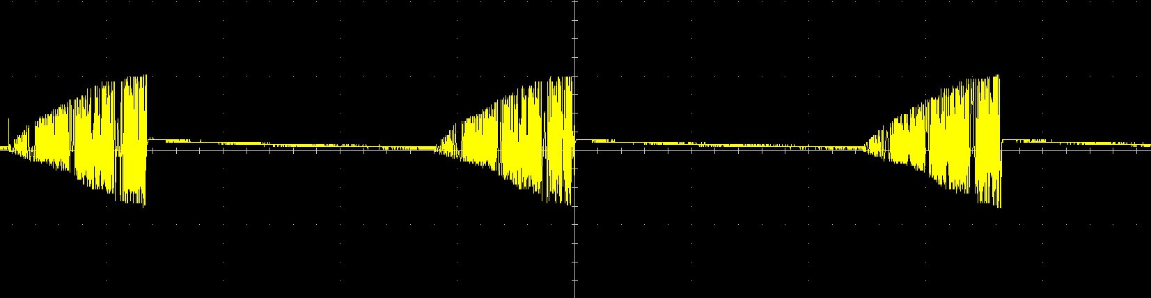
15V, there you can see absolutely fine shape due charging process and adequate timings
![]() 18V, everything goes even faster, it's logical, because with greater voltage you can achieve target energy (current on coil) quicker
18V, everything goes even faster, it's logical, because with greater voltage you can achieve target energy (current on coil) quicker
You can change oscillations of energy by changing reference voltages also
Well, what about conservation of energy now?
Here you can see current on a coil. I think it's legitimate to say, that there we see about 67% duty cycle![]() And also 15V VCC with 65mA power consumption.
And also 15V VCC with 65mA power consumption.
Connected directly to a traditional driver with same voltage and duty cycle electromagnet would consume about 295mA, so we can talk about 78% energy retained.
Pretty good for 2.5$ worth of components! :D
Later, deeper investigation of circuit's behavior would be taken, as well - improvements, if needed.
As this schematics and theory was a source of 90% doubts and that's proven to be true and fully working - only a question of time to make remaining things. Even if not very fast - well, now it's 99.9% possible! -
log(7.5) + energy saving!
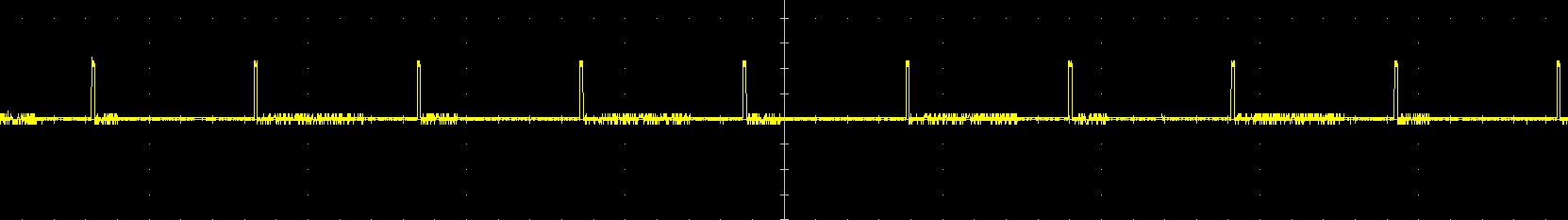
04/26/2019 at 19:47 • 0 commentsHere it is. Resistor connected to ground directly this time!
First of all I noticed stronger magnetic field, as well - low-frequency oscillations. I was happy about that and that is what I've seen on gates of MOSFETS:![]() 196Hz square wave, Nice!
196Hz square wave, Nice!
As predicted, everything was great on I_COIL input too:![]() (Yes, time/div on this pictures isn't same, but length of impulses is same for sure)
(Yes, time/div on this pictures isn't same, but length of impulses is same for sure)
And on capacitor:![]()
Then I felt very frustrated, I realized what reference voltages (which should affect energy boundaries) unable to change behaviour of board much. And then I discovered that:
![]() What it means? It means what output from Arduino is just PWMed thing, no DACs magic at all!
What it means? It means what output from Arduino is just PWMed thing, no DACs magic at all!
And I don't think what it's any good for our circuit, then it seems what some low-pass filter is needed... Or I would connect that to the voltage dividers, temporary, because it's easier and works pretty well.
Overall, everything is going as needed.
I can't say much about retaining of energy now, but if you very curious:
- Board consumes 30mA
- As you can see from control signal on gates, there is 30% duty cycle
- Usually it consumes around 270mA (connected directly to PSU)
- So it retains about 60%+ of energy somehow!
(even with wrong behaviour of PWMed reference voltages) -
Control circuit is there! (almost.)
04/25/2019 at 10:49 • 0 commentsYesterday, I managed to solder everything in place!
![]() Looks quite tangled, next time I would think twice before counting on wiring that much, maybe two layers worth hardship to fabricate, it gets complicated then it's needed to change something there with this amount of not-so-solid wiring above components :D
Looks quite tangled, next time I would think twice before counting on wiring that much, maybe two layers worth hardship to fabricate, it gets complicated then it's needed to change something there with this amount of not-so-solid wiring above components :D
When everything connected it looks like that:![]() V_TRG (see previous logs with schematics, if curious what is it) here connected directly to the power supply, reference voltages connected to analog voltage outputs of an Arduino with great hope to play with parameters afterwards... But ---
V_TRG (see previous logs with schematics, if curious what is it) here connected directly to the power supply, reference voltages connected to analog voltage outputs of an Arduino with great hope to play with parameters afterwards... But ---
But then I realized what something went wrong. Well, board consuming 0 current (according to my 5A PSU analog indicators of course), I can feel a slight field around the electromagnet, but too little. Then I connected an oscilloscope (1ms/div):![]() So there it is! This is a voltage which goes from S-R latch to the gate of transistors. So far looks not that bad (except of 30% duty cycle)
So there it is! This is a voltage which goes from S-R latch to the gate of transistors. So far looks not that bad (except of 30% duty cycle)![]() And there fun things started! This is a voltage on I_COIL input which theoretically represents current on electromagnet, however... It is 10V/div, so as I tried to measure voltage on the 0.1 Ohm resistor connected in serial with a coil - this would mean, what in some time periods there is around 100 Amps. Looks pretty awkward, isn't it?
And there fun things started! This is a voltage on I_COIL input which theoretically represents current on electromagnet, however... It is 10V/div, so as I tried to measure voltage on the 0.1 Ohm resistor connected in serial with a coil - this would mean, what in some time periods there is around 100 Amps. Looks pretty awkward, isn't it?
Well, it is. Because then I connected oscilloscope directly to the resistor, there wasn't anything like that.
That means, that I must figure out how to measure current (representing energy of field) correctly without damaging energy-retaining process.
Trivial task, but It may require two independent grounds to prevent leakage of electrons. I hope it wouldn't be necessary (because I'm lazy! ahaha) -
log(6)
04/23/2019 at 10:10 • 0 commentsThis log gonna cover how things going, pictures of how stripe production looks
(with some troubleshooting)![]() Here you can see new version of mold and PCB for a control circuit. Now I'm waiting for electronic parts to arrive, this must happen this week, so I think first inspections of this board are gonna be available this week also.
Here you can see new version of mold and PCB for a control circuit. Now I'm waiting for electronic parts to arrive, this must happen this week, so I think first inspections of this board are gonna be available this week also.
Production
First of all, you need to align magnets in row, so they poles are gonna be in right order. Then you need to mark them to prevent disorder:![]() On next step you should place them in needed order into mold, gluing magnets to the opposite side of the mold: (to fixate magnets while pouring epoxy inside)
On next step you should place them in needed order into mold, gluing magnets to the opposite side of the mold: (to fixate magnets while pouring epoxy inside)![]()
![]()
Cover everything with vaseline. (or similar, so epoxy wouldn't stick to the mold)
Then, pour epoxy into mold:![]() Cover top cover with oil in needed places: (to prevent epoxy from rushing there)
Cover top cover with oil in needed places: (to prevent epoxy from rushing there)![]() And close everything tightly with a stripe inside!
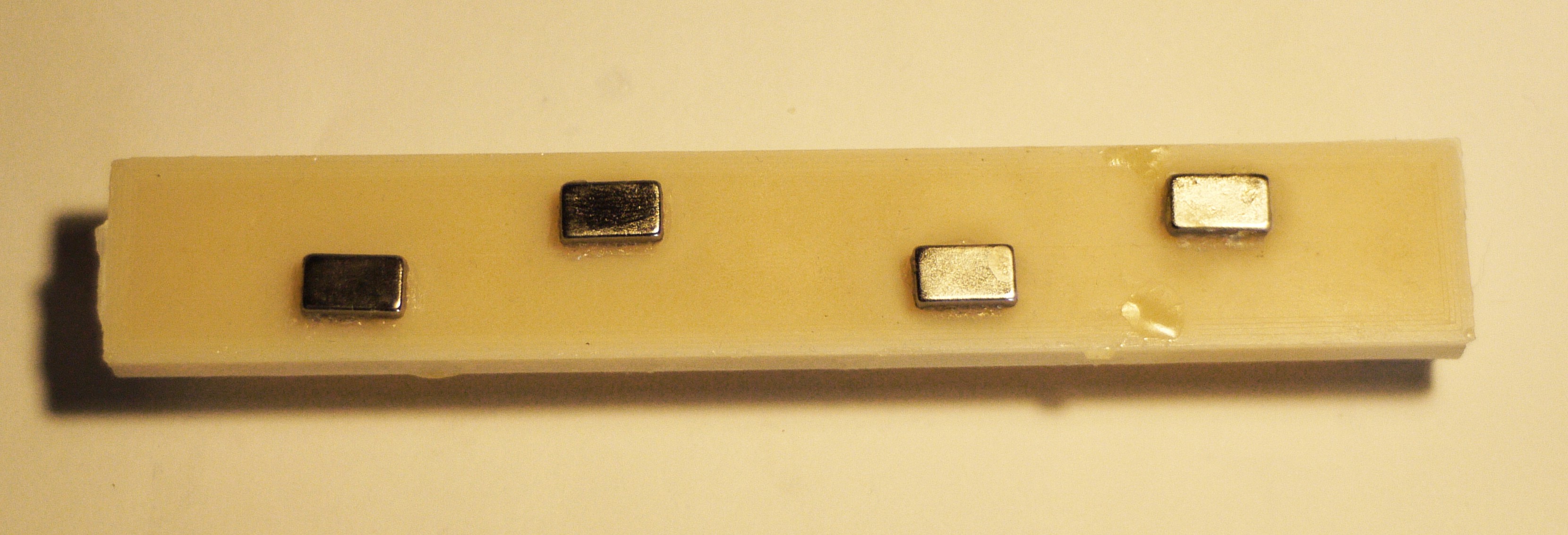
And close everything tightly with a stripe inside!![]() Result on the next day:
Result on the next day:![]() Troubleshooting
Troubleshooting
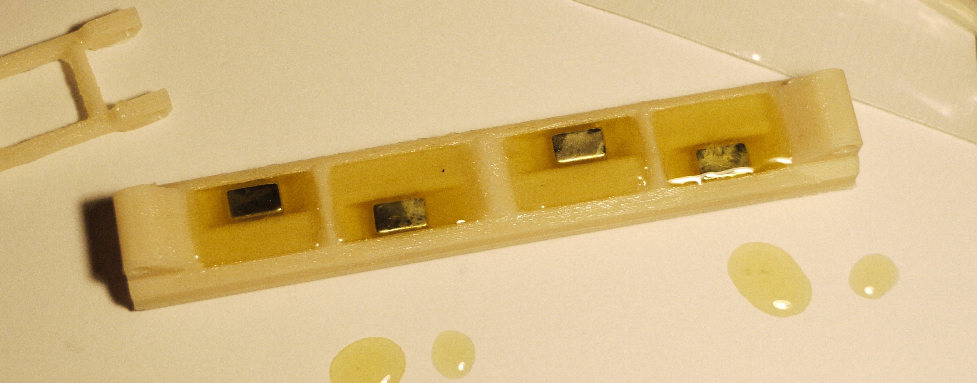
As you can see, something is wrong on the right - there is no epoxy on sides! It can be frustrating, because mold was filled on 100% - we have a photo which shows pretty much it.
Well... It WAS filled, but then everything were sucked (with the help of capillary effect)![]() If one part isn't sopped into epoxy - then, it's being drained. Natural selection.
If one part isn't sopped into epoxy - then, it's being drained. Natural selection.
So, to fix that - we need to modify top cover, so it would do sopping better.
(it's not hard at all, thankfully)
Next update is going to be about electronics, yes! Finally! :D
P.S. Of course if my supplier of electronic parts wouldn't be so slow as usual. -
Structure, again!
04/19/2019 at 22:25 • 0 commentsLate update about what has been done today
New proportionsPrevious test showed, what all structure works with help of chain reaction (except of pivoting torque and pulling force), since attraction of first elements (closest to magnets) in chain is bigger - they are main players at the start.
Also, contraction rate is very important, as elements aren't completely flat - their shape (for central elements of an actuator) defines, how much it can be contracted.
That's why I decided to differ lengths of elements, making smaller angles. As you can see, on previous version there were 45 degrees on side of each element:![]() There is comparison between versions of molds:
There is comparison between versions of molds:![]() On the right side we have new version of mold with modified central parts, they would give us additional 30 degrees of freedom at least! Also, this version has few minor changes to improve flexibility with preservation of rigidity, hopefully.
On the right side we have new version of mold with modified central parts, they would give us additional 30 degrees of freedom at least! Also, this version has few minor changes to improve flexibility with preservation of rigidity, hopefully. ![]()
With new proportions, behavior changed a little, so elements closest to the magnet are being folded faster than central - that corresponds to chain reaction principle, it would be interesting to see, how it affects overall dynamics.
Now it's being 3d printed, it would be possible to do something with it on Monday.At the end - photo of a previous version.
![]() Magnets glued to the bottom to arrange magnets properly inside of epoxy.
Magnets glued to the bottom to arrange magnets properly inside of epoxy. -
Structure
04/17/2019 at 16:52 • 0 commentsAnd a little update about structure tests
![]()
Here you can see two test stripes - first, held by a caliper to prevent collapse - is a two stripes stitched together with 24kg magnet on each side (temporary replacement for an electromagnet) and second is a stripe example.
![]() Side view^
Side view^
What about performance?
With 24kg magnets it gives about a 1.6N on full length. On other hand, if we reduce length two times, there would be about a 5N of force. Not so good for a conventional electromagnets control method (which would consume 16W of power on that), but if control circuit would retain 90% of power, 1.6W consumption for 1.6N of force isn't bad at any rate, work of magnetic field in this situation would be a main factor what affects energy consumption.
I'm optimistic about it! Current structure isn't greatest and needs some improvements, as well as greater implementation, but it's only a question of time.
Also I was happy to see what it isn't unstable at all, all magnet to magnet interactions are working as predicted without precise fabrication -
Some improvements
04/17/2019 at 14:50 • 0 commentsA little update here.
After some thinking I decided to change way how comparators are powered.
In previous version they were connected directly to PSU/battery, because supply voltage of a comparator determines range of permitted voltage of an input signal, however it seems what big input voltages aren't necessary here.
Then we measure current on coil we are interested to put as little resistance in serial to coil as we can, thus it would dissipate less heat and we aren't losing overall efficiency, and as a resistance is small - voltage, according to Ohm's law, would be small too.
Even if we forget about efficiency, it's hard to get 10+V from a MCU, so maximum 5V input voltage is a great choice here.
Also I added Hi-Z ground, because it's kind of required to measure voltage from a part of high-current circuit without even higher current leakage. So schematics now looks like this:![]() It's time to fabrication, because PCB's are ready and they are even more symmetrical now! : )
It's time to fabrication, because PCB's are ready and they are even more symmetrical now! : )![]() And after all I'll return to "How it works" once more, because now I drew more detailed graphs about it:
And after all I'll return to "How it works" once more, because now I drew more detailed graphs about it:![]() This is how this circuit should work. I'm very curious now, what is minimum amplitude of energy oscillations for this method, because it determines smoooothness. And also curious if I can connect this circuit to a conventional electric motor (though, it doesn't needs it very much, motors are different and they are already know how to use magnetic energy without dramatic looses, thanks to their rotating parts)
This is how this circuit should work. I'm very curious now, what is minimum amplitude of energy oscillations for this method, because it determines smoooothness. And also curious if I can connect this circuit to a conventional electric motor (though, it doesn't needs it very much, motors are different and they are already know how to use magnetic energy without dramatic looses, thanks to their rotating parts)
P.S. lower/upper bound E are defined by V1_REF and V2_REF, capacitor is a C3 on board
linear actuations for everyone!
cheap artificial pseudo-muscles here
 Fe cores are grey there, main reason why you can see them - nothing is between coil and core on sides (only electrical insulation), minimizing gap between wires and core is a crucial thing, as it defines inductance pretty much!
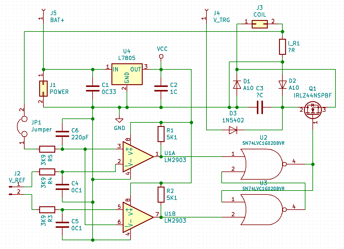 New:
New: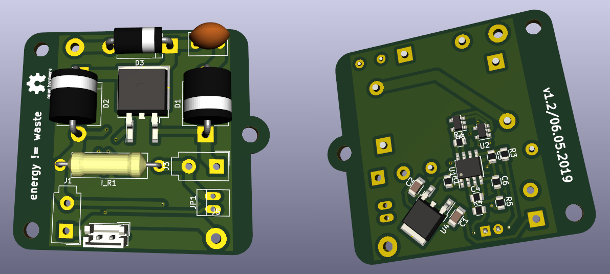 Around 5x5cm now, with mounting holes
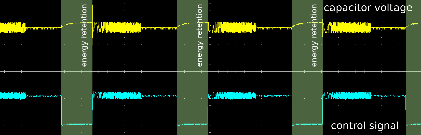 And there is only one major change in schematics (of course, previously there were two transistors, but anyway, C3 is connected to ground on last PCB and D2 was connected to ground in experiments manually by wiring, while I was working onto question how to read current on electromagnet properly),
 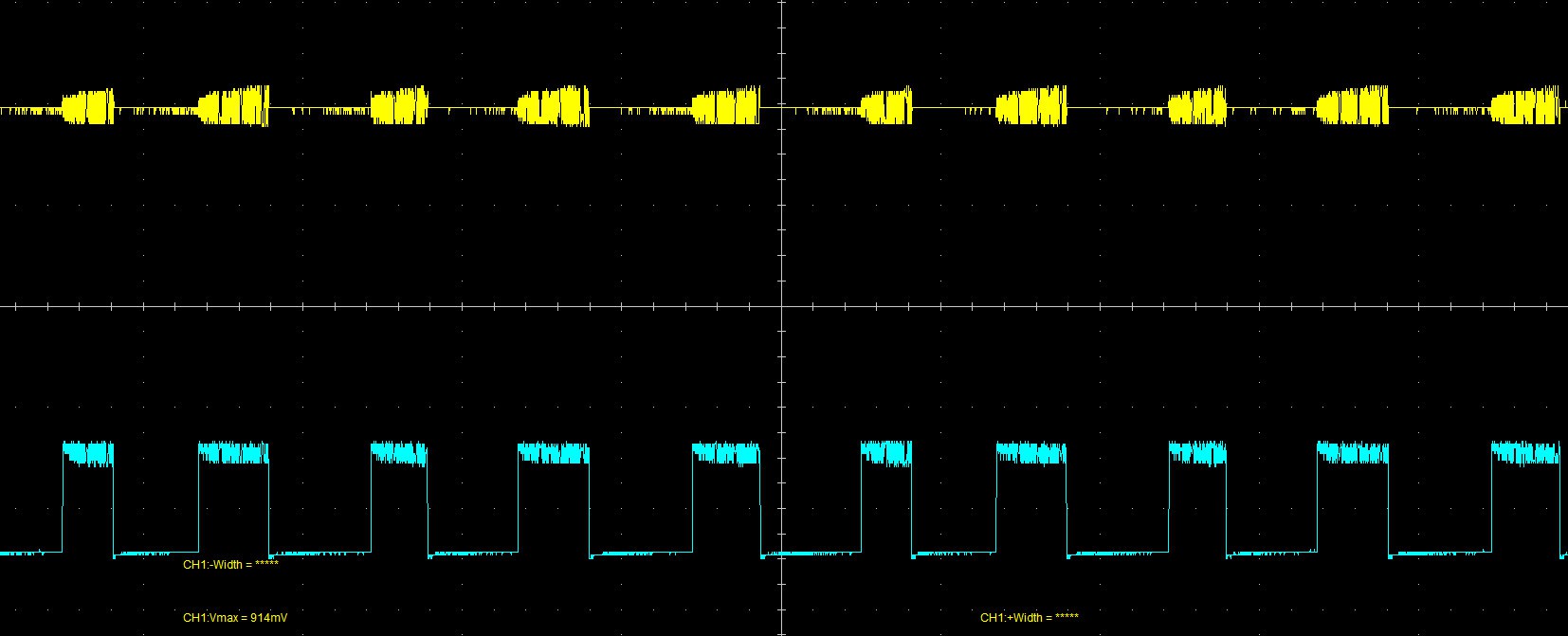 - typical current here must be around 108mA (10V, 40% duty cycle avg.)
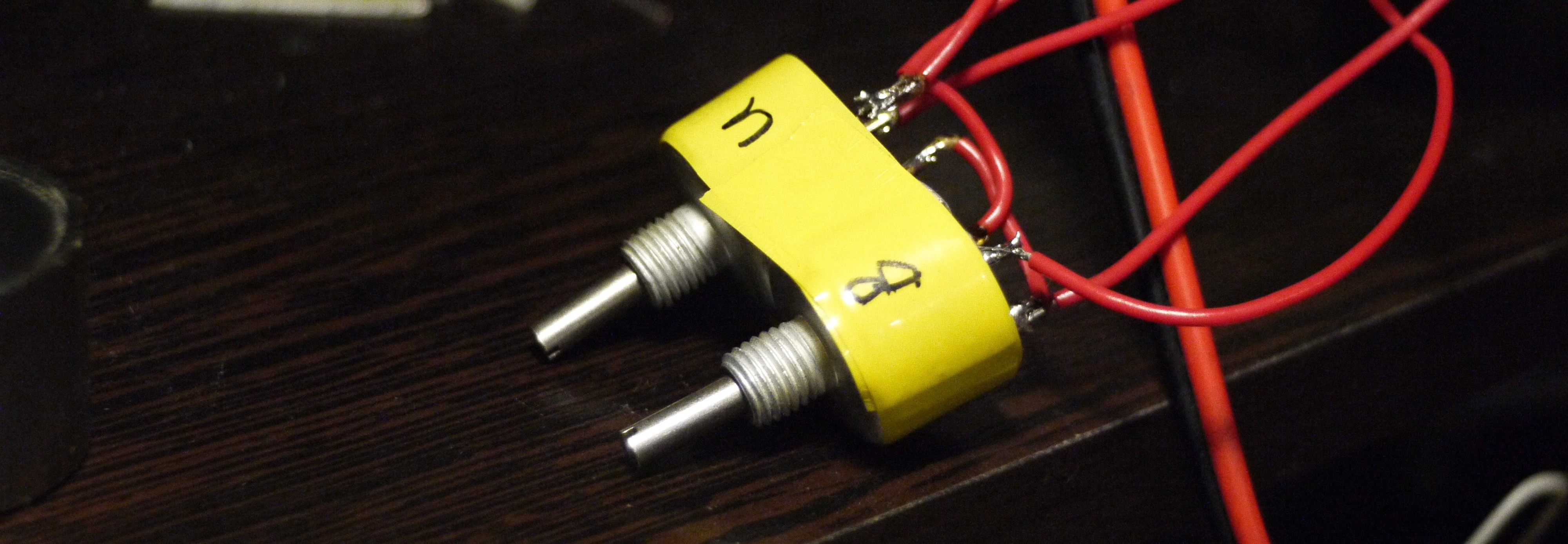 And yes, it seems that everything works now!
 13V, as you can see, it's difficult for circuit to charge magnetic field as needed, so process of charge is really slow and uneven
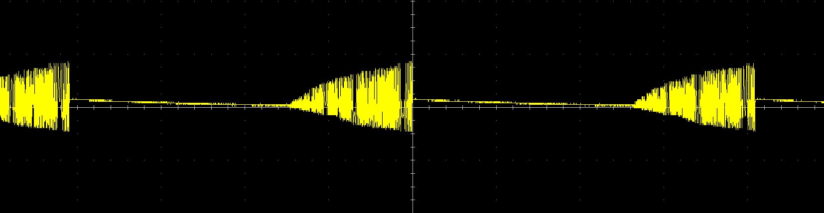
 18V, everything goes even faster, it's logical, because with greater voltage you can achieve target energy (current on coil) quicker
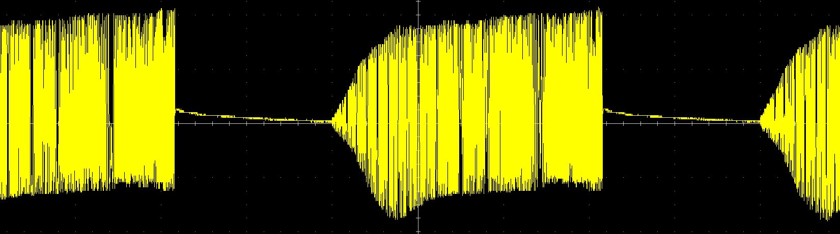 And also 15V VCC with 65mA power consumption.
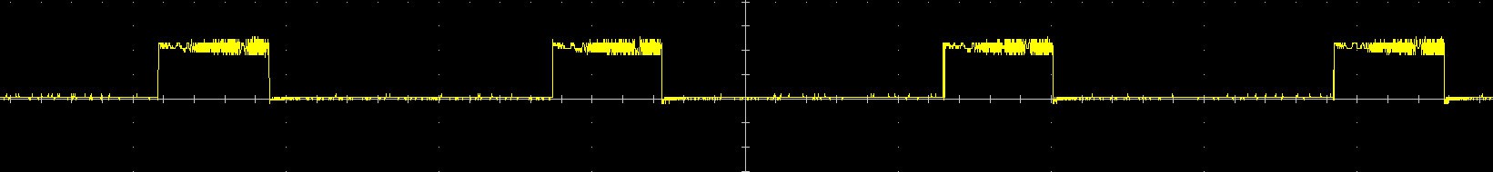 196Hz square wave, Nice!
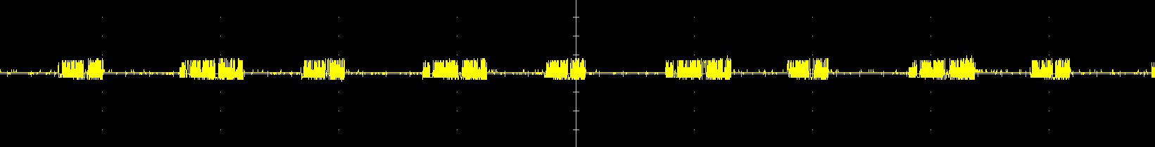 (Yes, time/div on this pictures isn't same, but length of impulses is same for sure)
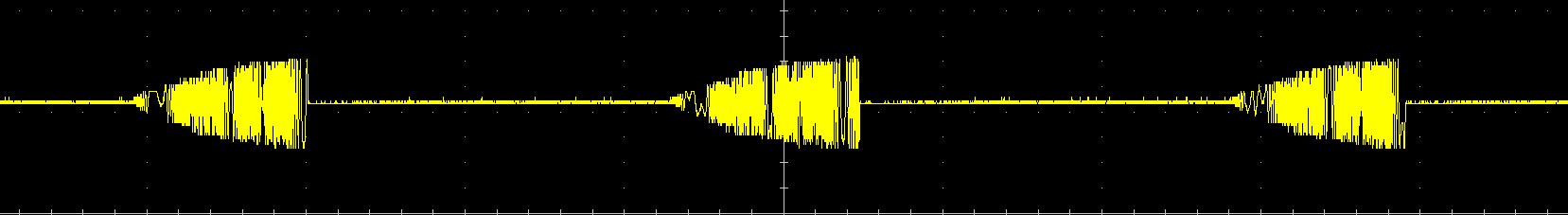
 What it means? It means what output from Arduino is just PWMed thing, no DACs magic at all!
 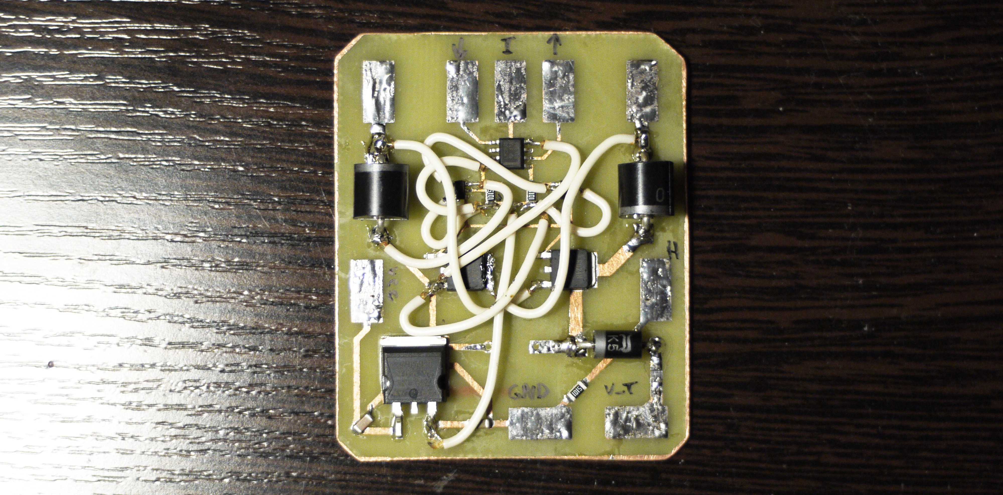 Looks quite tangled, next time I would think twice before counting on wiring that much, maybe two layers worth hardship to fabricate, it gets complicated then it's needed to change something there with this amount of not-so-solid wiring above components :D
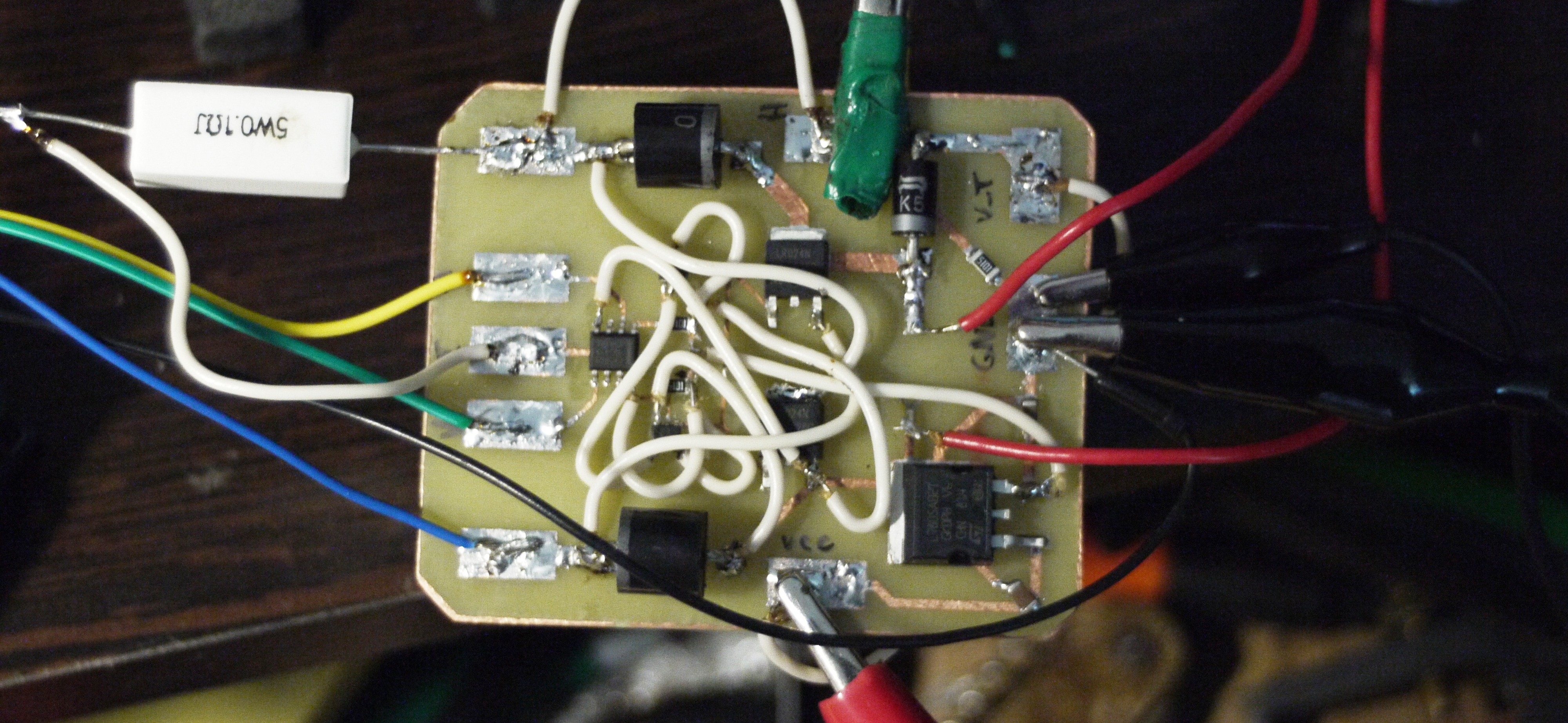 V_TRG (see previous logs with schematics, if curious what is it) here connected directly to the power supply, reference voltages connected to analog voltage outputs of an Arduino with great hope to play with parameters afterwards... But ---
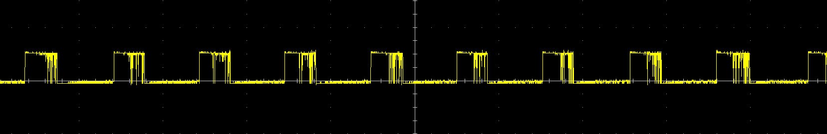 So there it is! This is a voltage which goes from S-R latch to the gate of transistors. So far looks not that bad (except of 30% duty cycle)
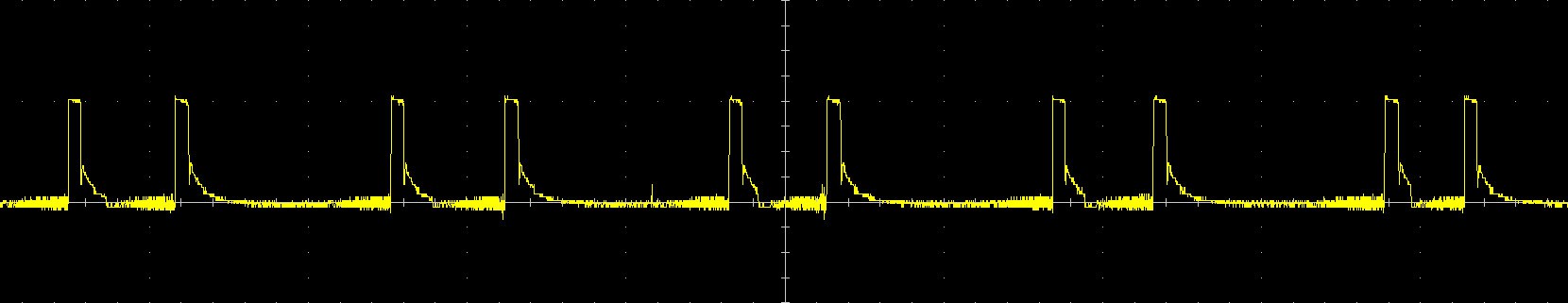 And there fun things started! This is a voltage on I_COIL input which theoretically represents current on electromagnet, however... It is 10V/div, so as I tried to measure voltage on the 0.1 Ohm resistor connected in serial with a coil - this would mean, what in some time periods there is around 100 Amps. Looks pretty awkward, isn't it?
 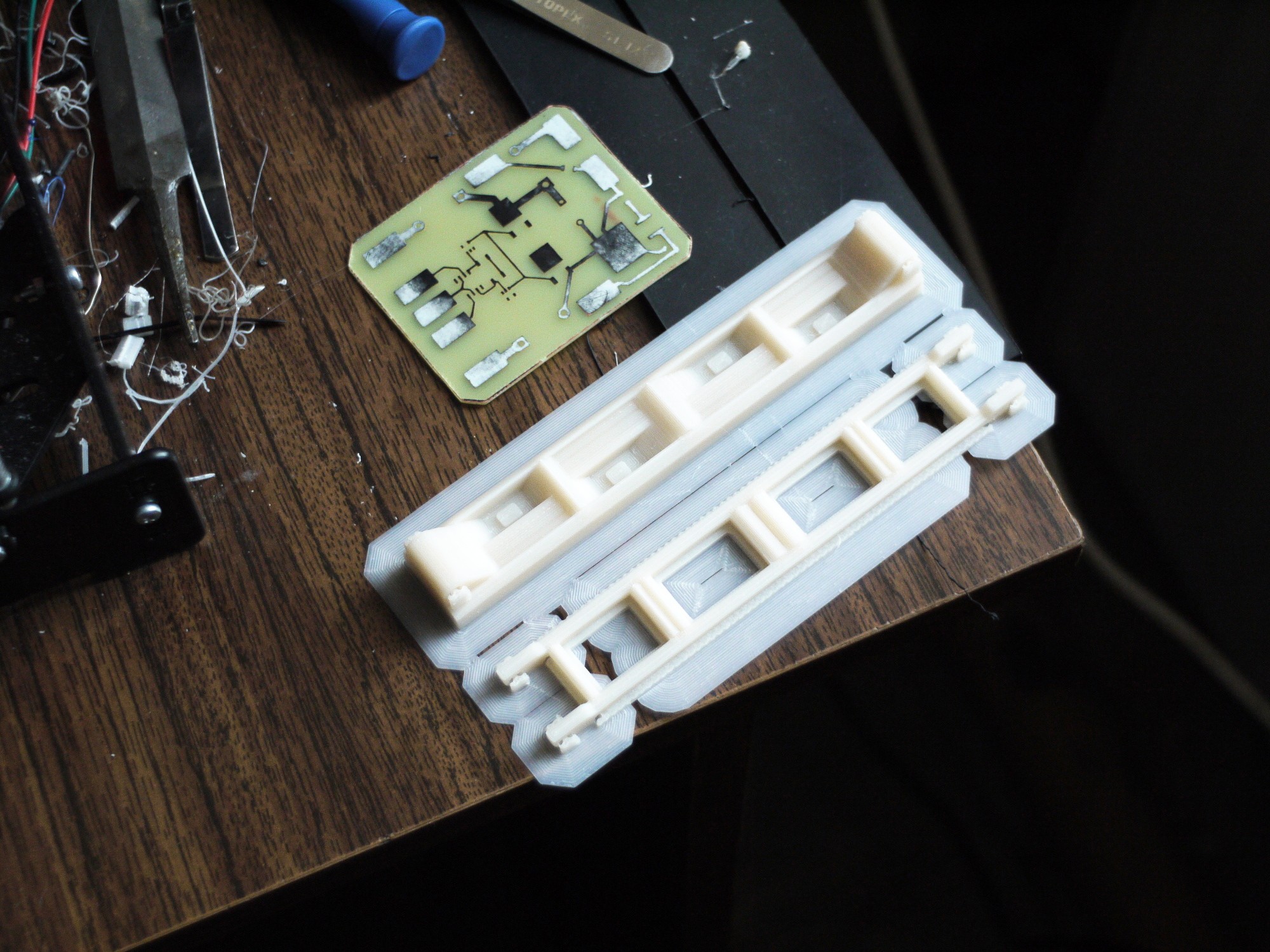 Here you can see new version of mold and PCB for a control circuit. Now I'm waiting for electronic parts to arrive, this must happen this week, so I think first inspections of this board are gonna be available this week also.
 On next step you should place them in needed order into mold, gluing magnets to the opposite side of the mold: (to fixate magnets while pouring epoxy inside)
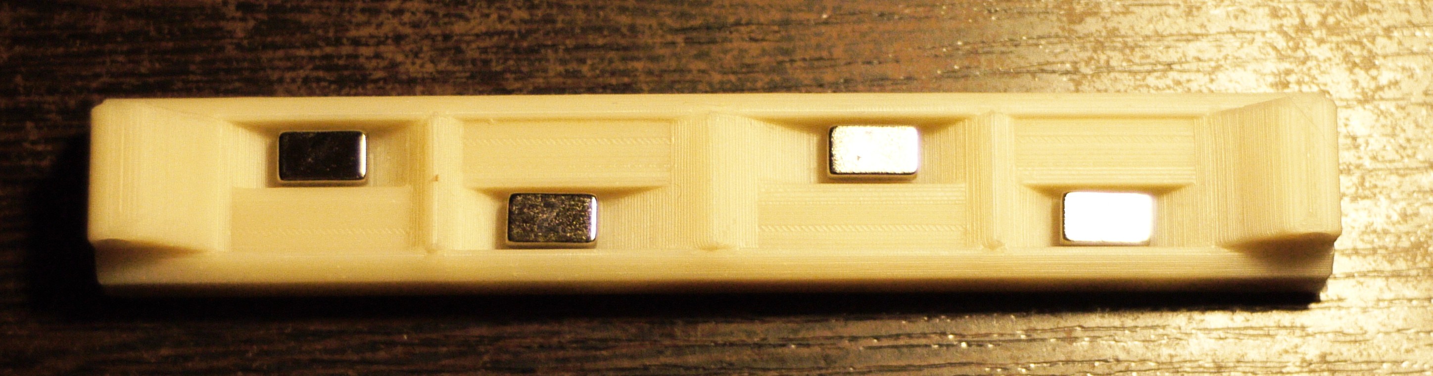
 Cover top cover with oil in needed places: (to prevent epoxy from rushing there)
 And close everything tightly with a stripe inside!
 Result on the next day:
 Troubleshooting
 If one part isn't sopped into epoxy - then, it's being drained. Natural selection.
  There is comparison between versions of molds:
 On the right side we have new version of mold with modified central parts, they would give us additional 30 degrees of freedom at least! Also, this version has few minor changes to improve flexibility with preservation of rigidity, hopefully.
 Magnets glued to the bottom to arrange magnets properly inside of epoxy.
 Side view^
 It's time to fabrication, because PCB's are ready and they are even more symmetrical now! : )
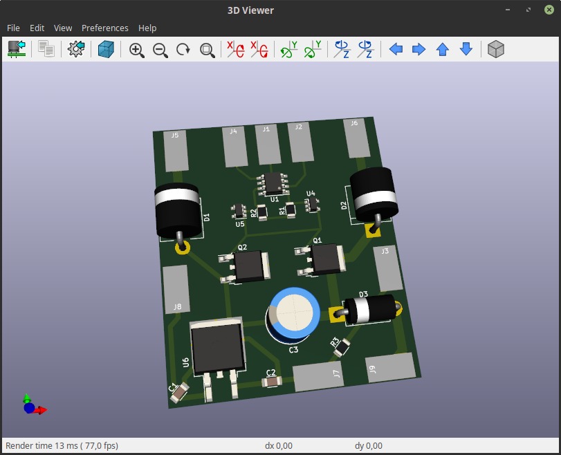 And after all I'll return to "How it works" once more, because now I drew more detailed graphs about it:
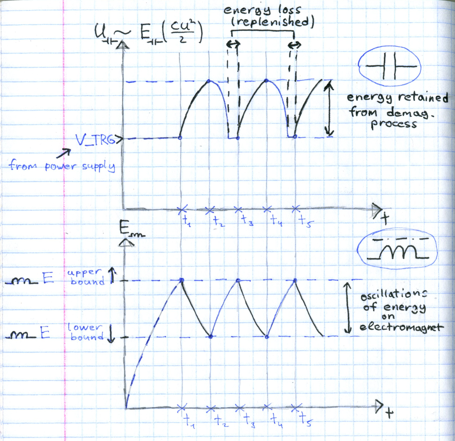 This is how this circuit should work. I'm very curious now, what is minimum amplitude of energy oscillations for this method, because it determines smoooothness. And also curious if I can connect this circuit to a conventional electric motor (though, it doesn't needs it very much, motors are different and they are already know how to use magnetic energy without dramatic looses, thanks to their rotating parts)