Close
0%
0%

Soldering lightsaber

The fastest soldering ever

Similar projects worth following
I am obsessed with creating the quickest soldering station ever. If a sports car can go from 0 to 60 in less than 3 seconds, I want my soldering iron to go from 25*C to 400 in 2 seconds. Between picking it up from the stand and touching its tip to the PCB it should be ready to fire. The answer to this challenge? Machine learning on a simple microcontroller.

Beginnings and purpose

   I created another soldering iron in the past and I've been improving the firmware ever since then. 

https://hackaday.io/project/94905-hakko-revenge

   This soldering station has the following sensors which I plan to keep on this new iteration and use in the new firmware algorithm: Tip temperature, PCB temp (and initial ambient temperature), Voltage measurement sensor, Internal timer. 

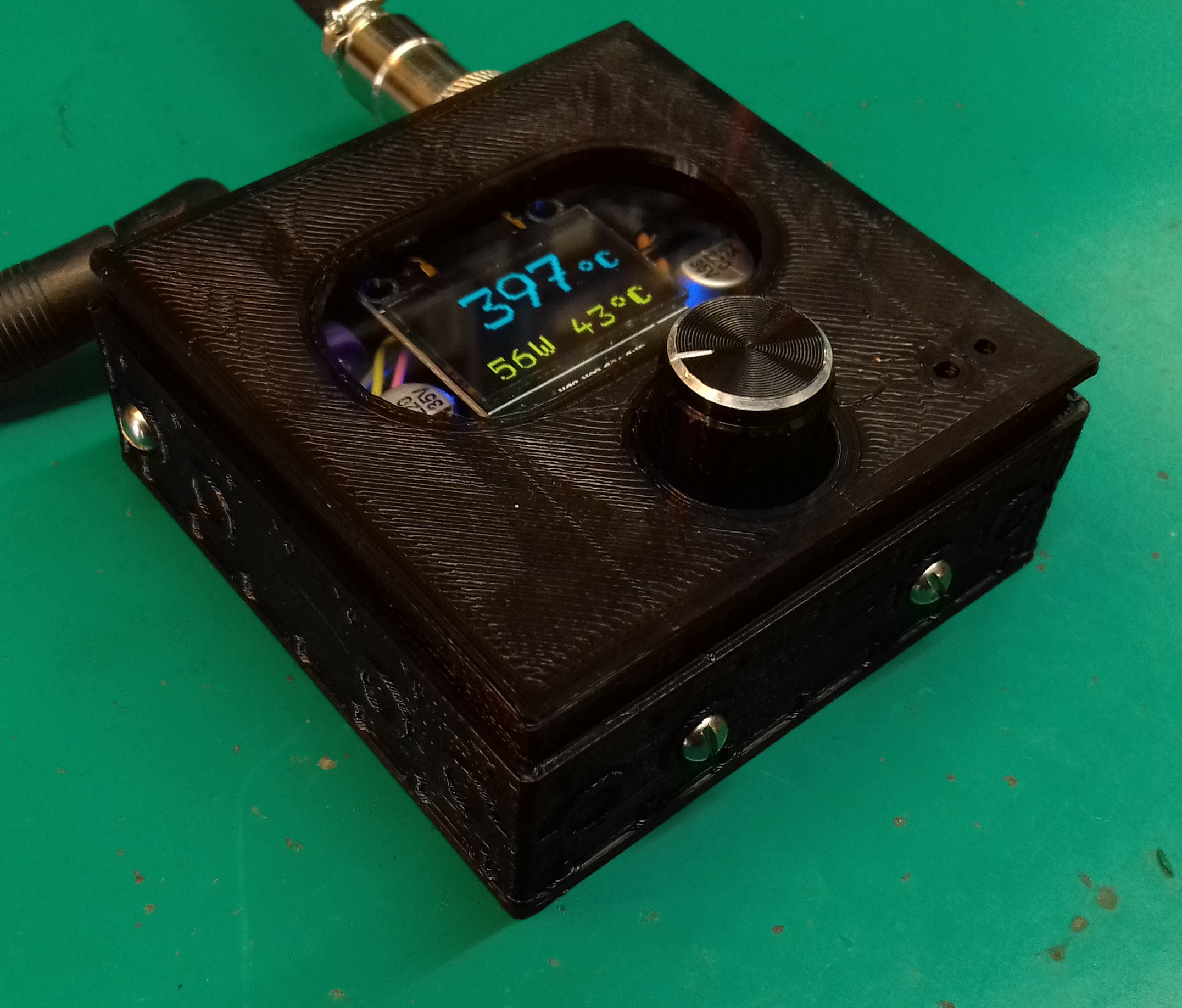
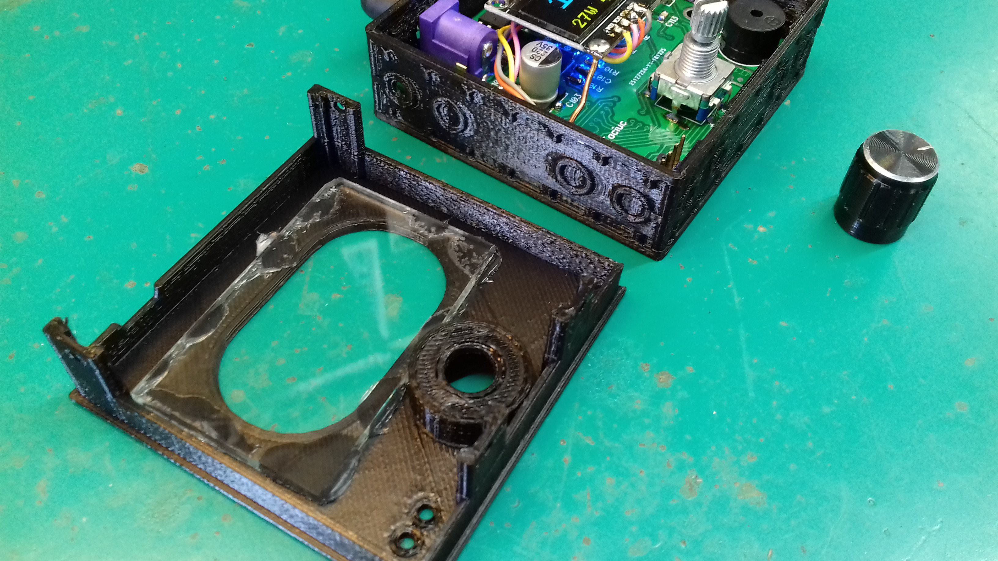
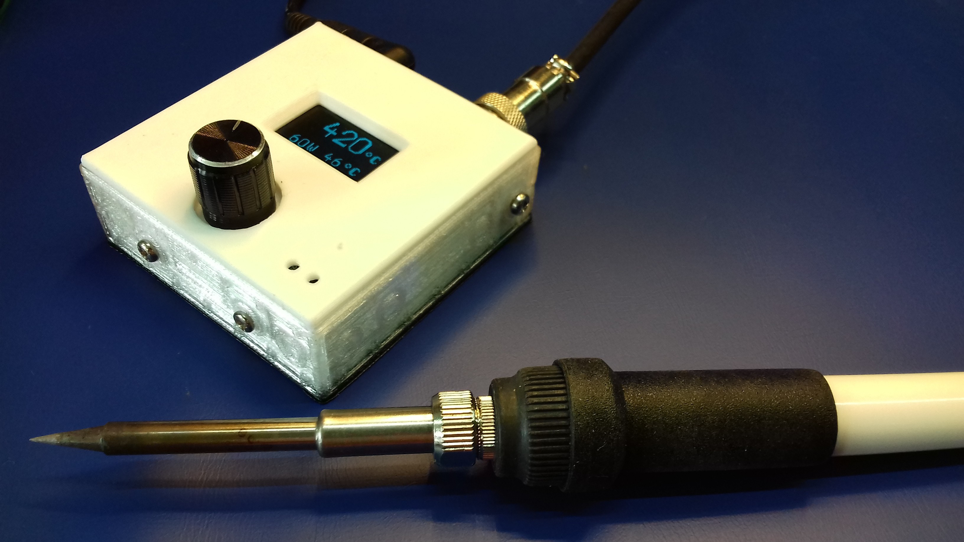
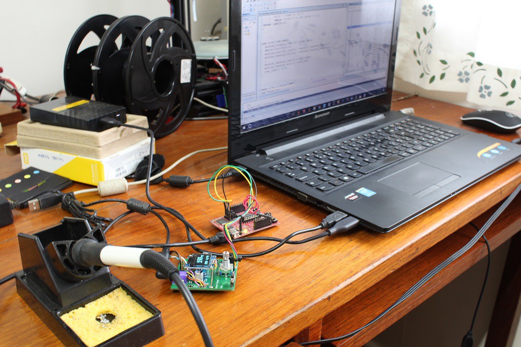
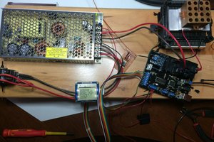
   So these pictures I uploaded into the gallery are the actual prototype I experiment with. It uses the PCB from the Hakko Revenge project and once I'll have some measurable results with the firmware I plan to move ahead and design a 2020 PCB version for this one. 

   Since I use a t12 (or Ts100) tip which can heat up really quick, I was able to achieve good heating times. This previous project of mine goes up from the room temperature (25*C) to the soldering temperature (above 320*C) in about 6 seconds. Also, when it heats up from the standby temperature (190*C) to the soldering temperature it only takes about 3 seconds. Of counrse, this can only happen if I power it at higher voltages between 24 and 29V. 

   Fast, fast, fast! I always wanted to be able to make it faster and smaller and since I am redesigning everything now, I thought this is a good time to come up with a new approach. As you can see from these recent pictures, I also added a 0.96'' OLED display to it and now looks way much better. 


Why I cannot make it faster in the conventional way?

This type of t12 tip might be small and of a low mass, but it has the drawback of having the thermocouple connected in series with the heating element. This means that I have to power the heating element blindly for a while and then disconnect the power source and perform the temperature measurement on the same two wires. So this results in not being able to keep the heating element always on and it must be controlled through a PWM cycle that cannot be greater than 60 or 70% in some cases. So 30% of the time I have to read the tip, hence, I get to power the heating element less.
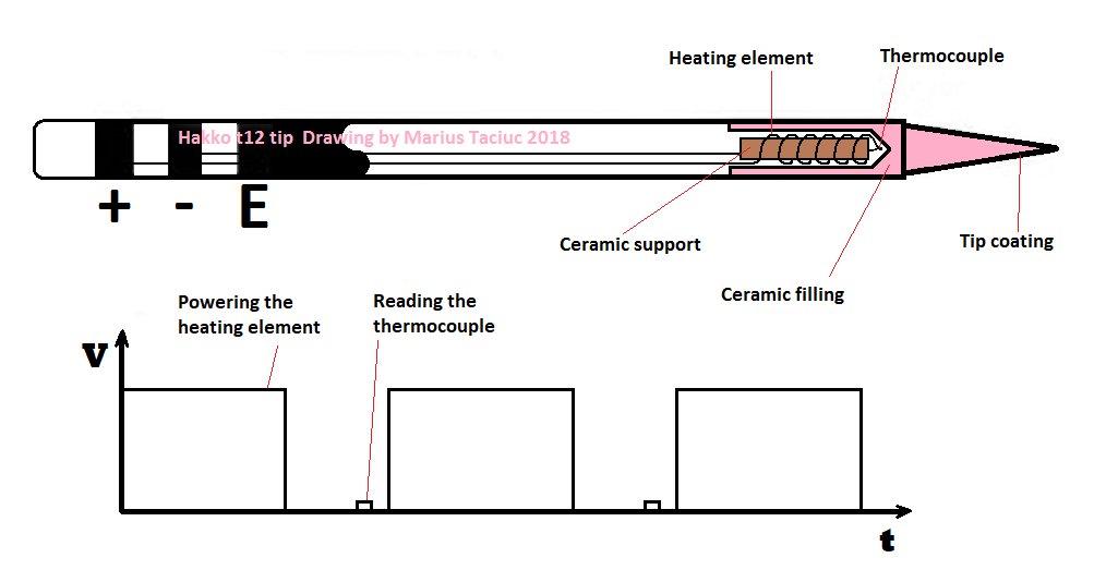
In order to make it even faster than it currently is, I tried to experiment with the PWM and with shrinking down the thermocouple reading times so I can expand the time frame for powering the tip. 

   It doesn't work. I cannot shrink down the sensor's reading window, since if I do the reading right after I apply power to the lines, I get all sorts of inductive noises bouncing off inside this circuit. So I really have to wait for some couple of ms for the line to quiet down before I can perform the reading of the thermocouple. I even tried to setup the PWM module to operate the heating element automatically at different frequencies and to only interrupt this PWM from time to time less often to perform the reading. I got the same thing and if I try to do the reading less often, then the tip's temperature becomes more bouncy and less accurate. So this was not a solution.  


Solution: May the force be with you

The solution i'm thinking of is to power the heating element at 100% PWM blindly, for an undefined period of time at startup. <grin> so not only I have a sports car that can do 0 to 60 in 3 seconds, but the driver is also blindfold. How can I power the heating element for the right amount of time without reading the temperature sensor not a single time during this operation and still stop at the proper temperature? Moreover, how can I do that at different input voltages or at different room temperatures?

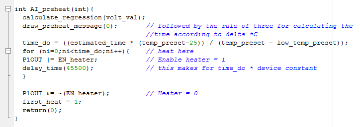
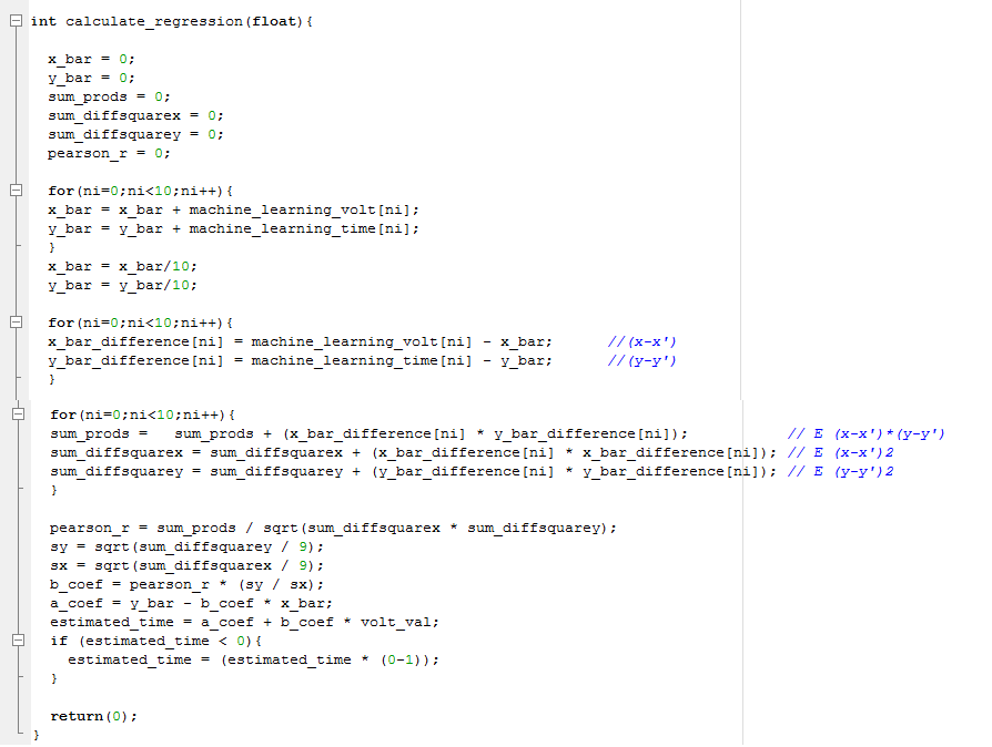
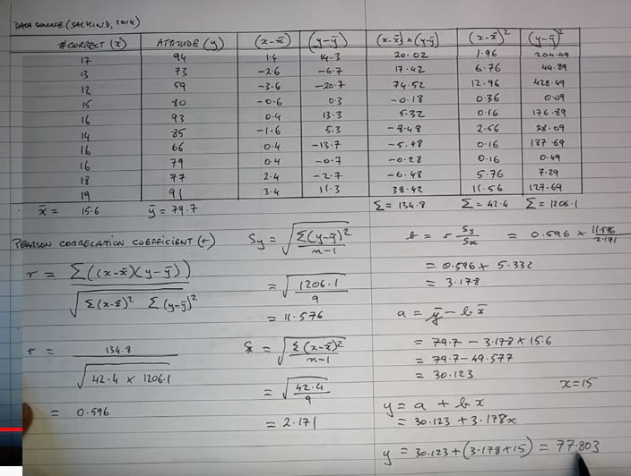
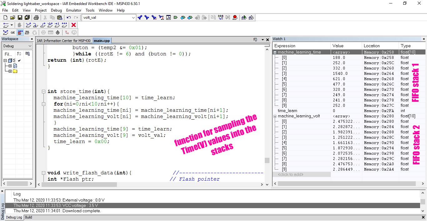
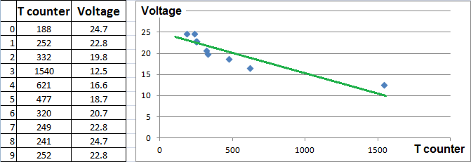
   This is where the machine learning part comes in. I am planning to have the microcontroller sample different heating times at different input voltage values and then based on these dates, to work out a linear regression and estimate the necessary heating time. Then it should subtract the ambient temperature ∆⁰C variation from the nominal 25⁰C and add...

Read more »

Soldering_lightsaber_2_1_backup.txt

Firmware update

plain - 60.00 kB - 03/27/2020 at 07:00

Download

Soldering_lightsaber_2_0_backup.txt

First functional firmware.

plain - 59.68 kB - 03/18/2020 at 12:14

Download

Soldering lightsaber_A1_nodisp.dip

First PCB draft for Soldering Lightsaber

dip - 430.19 kB - 03/12/2020 at 07:13

Download

View all 6 project logs

  • 1
    Disclaimer

    I plan on adding the first code draft, which I write and test now. But before I do so, I want to leave this disclaimer here. 

    !!! Disclaimer - read this !!! 
    This firmware is purely for experimental and demonstrative purposes. This AI firmware is not the final tested version and it could take erroneous decisions that could lead to hazards. The designer assumes no responsibility for any of these consequences. Hazards could include, but are not limited to: severe injuries, explosions, domestic fires, death.
    !!! Exercise caution at all times when testing it at your own risk !!! 

    I just get chills when I think that I entrust a 50W - 400*C heating element into the hands of a self learning, decision making machine who could set my house on fire when I leave the room. Errr! So please be careful. At least in the prototype phase until we conclude that is safe. 

  • 2
    How to connect the 0.96'' OLED display

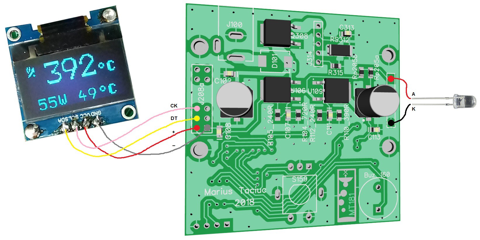
    Like I said, before I redesign this, I will use the PCB from my previous project. I uploaded the layout here so you don't have to go looking for it. This is how I connected the OLED display and the LED. 

    Then I bent the LED underneath the display and used a thicker piece of copper wire to secure the OLED into position like in the picture below:

    I am planning to use that backlight LED to illuminate around the knob of the encoder. Or I might print a transparent case and the LED will shine through. 

View all instructions

Enjoy this project?

Share

Discussions

justin.richards wrote 04/09/2022 at 03:05 point

Great project requirements :- 25 - 400 in zip.  

Mine was to power T12 from 24VAC (xfmr found in a hakko knockoff) , because! 

I had similar issues with bouncing readings. I found 8mS OFF before read mostly ok  but 12mS was the sweet spot.  However, my whole cycle is 1020mS, so 12mS is about 1.5% min required OFF time.  

  Are you sure? yes | no

kempil wrote 07/01/2021 at 14:51 point

Hi Marius, can you provide the schematic?  kemalmete@hotmail.com

  Are you sure? yes | no

salmanisheikh wrote 08/26/2020 at 15:02 point

where is the parts list? I got PCBs made for the project.

  Are you sure? yes | no

valle wrote 06/10/2020 at 17:32 point

Hey Marius,

love the idea! Great project and very interesting. I, too always find that soldering irons do take too long.

About your AI firmware part:

I would recommend a slightly different approach. You could model the soldering iron with all its thermal capacities, resistances and temperatures and use an unscented kalman filter to determine these. It's sort of like your linear regression but on steroids. This should allow you to get pretty accurate results and it continuously readjusts itself to the environment.

  Are you sure? yes | no

salmanisheikh wrote 04/19/2020 at 03:04 point

how much is the pcb to make? I uploaded the board to pcbway but need to see the quote. Was looking for cheaper than oshpark as it’s a bit pricey there (but helping US over China if I get from osh Park and purple 🙂)

  Are you sure? yes | no

ralf.waldukat wrote 03/28/2020 at 10:47 point

You could also implement a negative thermal resistance.

The problem is that when you connect your soldering iron to the thing to be soldered the temperature drops. This can be offset. But you are feeling the temperature of the heating element, not the tip, and not of of the thing which is soldered.

There are multiple resistances in the way. You could cancel those out in Software. So if the heating element is outputting 40W you would have to lift the target temperature by xx degree to offset the thermal resistance.

The same is done in expensive power supplies.

And yes, you have to be careful with positive feedback loops ;) Ideally you shouldn't set a resistance which is higher than the lowest possible resistance.

  Are you sure? yes | no

Dan Maloney wrote 03/04/2020 at 16:39 point

An interesting idea. I look forward to updates.

  Are you sure? yes | no

Marius Taciuc wrote 03/11/2020 at 06:57 point

Thanks, Dan. So far, so good. The firmware seems to be coming together nicely and I will soon post a first draft and maybe a short video of the prototype. Stay tuned. Blessings from PNG.   

  Are you sure? yes | no

Similar Projects

Does this project spark your interest?

Become a member to follow this project and never miss any updates