Close
0%
0%

DIY hobby servos quadruped robot

Cheap 3D printed 4 legged robot, that almost looks like boston dynamics spot but moves like a newborn.

Public Chat
Similar projects worth following
Being a undergradute in physics and bored of solving paper problems, i decided to solve and apply a real world problems so i started this robotics project in order to introduce my self to control theory, studying its maths and practicing pragramming.
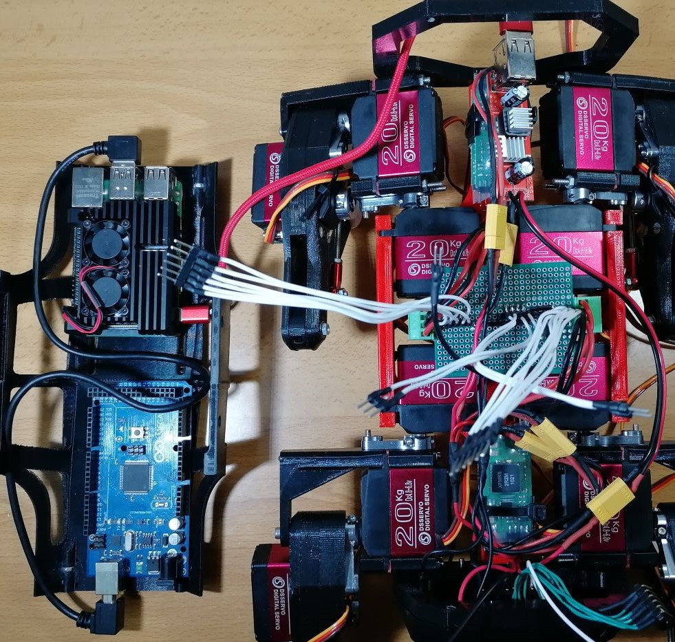
It runs with Raspberry Pi 4 as brain, plus an Arduino Mega for reading/writing of signals of 12 hobby servos and IMU, controlled by a PS3 Dualshock.

General Summary

The code which is mostly written by me, using python3 along with some typical libraries for the task, for now implements a walking loop inside a kinematic model, so you can command a pose to the body, as well as feet position and also velocity and directinal commands for the walking loop. Controlled by a ps3 controller via bluetooth.

Arduino is used for speed up the reading and writing of signals, so in the future i can add other sensor, as well as position feedback...

Lets see what this under 500$ robot can do:


Project log index (updated):

  1. Model and code explanation.
    1. The kinematic model.
    2. Step trajectory and Gait planner.
    3. Arduino code  and serial communication.
    4. Raspberry Pi communication interfaces.
    5. Calibrating the servos.
    6. PyBullet Simulation example.
    7. Future 3DoF foot sensor.
    8. Improving the leg mechanism and PCB board.
  2. Robot experiments.
    1. A simple walking method.
    2. Real robot vs PyBullet simulation.
    3. Hitting the robot.
    4. Quadruped robot meets my cat.
    5. A more stable walking.

💻💻💻💻 Code of the robot.


📚📚📚📚 Bibliography and readings of the project.


🔨🔨🔨🔨Bill of materials and price.


🏆🏆🏆🏆Makers that built the robot.


Why building a quadruped robot?

Appart from the interesting control problems that this robot involves, there are lot of interesting tasks this it can carry out and they are beginning to be demonstrated, as we have seen with Spot robot in the 2020 pandemic:

It's obious that there is still lot of work to do, but we are at the time where we can built one of these in our homes and have a very good aproximation of it.

There is a key factor in this robot, it doesn't need roads in orther to operate, so it can reach places that are very hard for a wheeled machine, so these 4-legged robot are ideal for tasks such as surveillance, recognition of areas not passable by vehicles and even rescues in areas with danger of collapse.

Finally, it is clear for now, that my robot isn't able to do those tasks, but for now i am satisfied that the robot walks stable and who knows if in the future it will be able to bring me a beer from the fridge, just by telling to it: 'dog bring me a beer!'

What problems will you face with this robot?

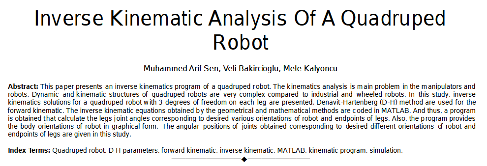
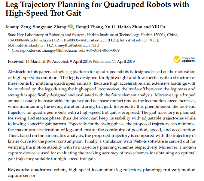
These legged robot have always amazed me, but it was hard to find easy to understand research, as well as a non-trivial mecanical designs plus complex maths. This makes the project hard to achive good results with DIY resources. So i rolled up my slevees and started reading papers from different investigation groups in the subject.

What my project apport to the maker community?

As this project is multidiciplinary, appart from designing my own version of the robot, i focused on its maths, solving different problems related with the movement of the robot, making a very looking forward model which only implements the maths necessary to run the robot, showing how every equation is related with the real robot and givin a general view of it.

This is not the most robust way of building a model, as in real world robots there are lot of additional maths methods in order to pulish the behaviour of the robot, for example, adding interpolation methods would make the robot performs smoother or building an state stimator + filter (kalman state stimator) would let you do very preccise meassurements on the robot and make its movements even more natural.


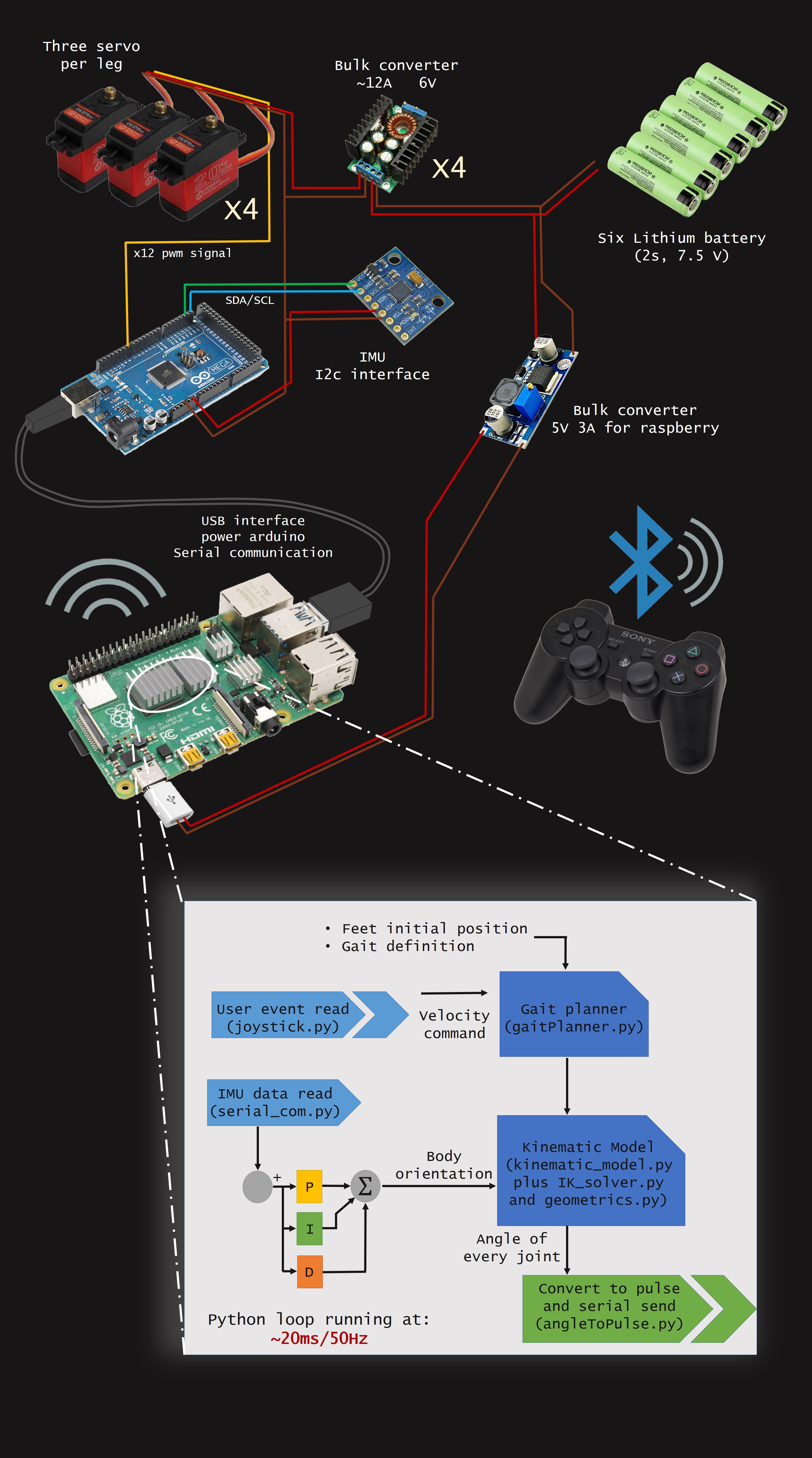
Visual scheme of electronics and model.

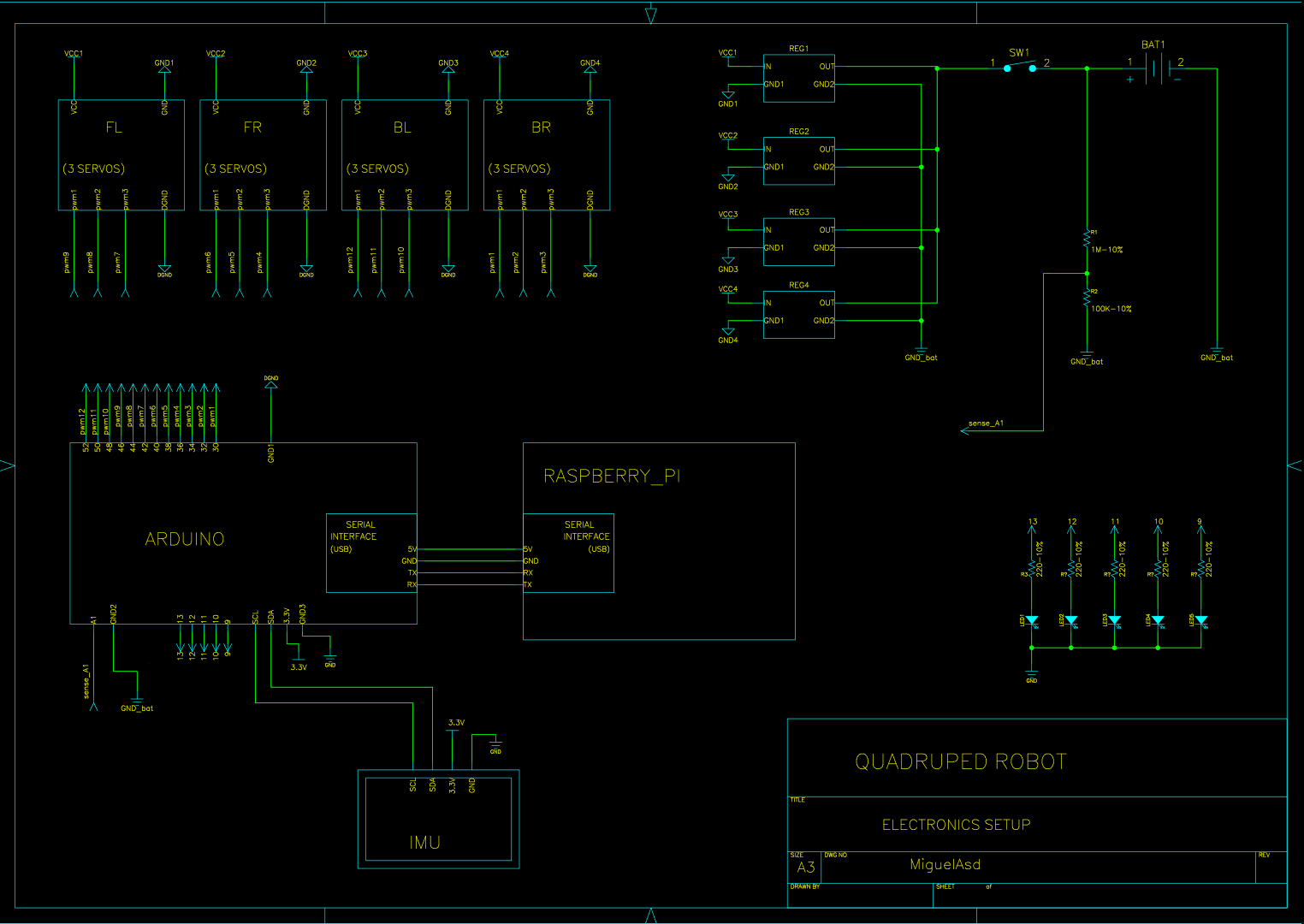
As you can see in the scheme, in this setup i use one bulk converter por 3 servos, with 4 bulk converters in total. This is because each servo drains up to 4A peak.

NOTE: This would not be a rigorous way of wiring, it is just a drawing.
Licensing

This project uses the GPL v3 license for all software related.

This project uses the Attribution-NonCommercial-ShareAlike 4.0 International for all hardware components.

Read more »

STL_files.zip

x-zip-compressed - 2.35 MB - 08/12/2020 at 18:25

Download

Quadruped robot_V2-STEP.zip

x-zip-compressed - 5.94 MB - 08/12/2020 at 18:36

Download

Quadruped robot_V2-IGES.zip

x-zip-compressed - 8.55 MB - 08/12/2020 at 18:36

Download

Electronics setup_full res.pdf

Adobe Portable Document Format - 82.65 kB - 07/07/2020 at 00:34

Preview

TPU_contact_x4.stl

Standard Tesselated Geometry - 605.26 kB - 08/12/2020 at 18:25

Download

View all 28 files

  • 12 × Servo DS3218 PRO version. 20 kg/cm torque and 0.1 s/60º.
  • 12 × Metal horns for the servos. Plastic one are not a choose, as they generate play.
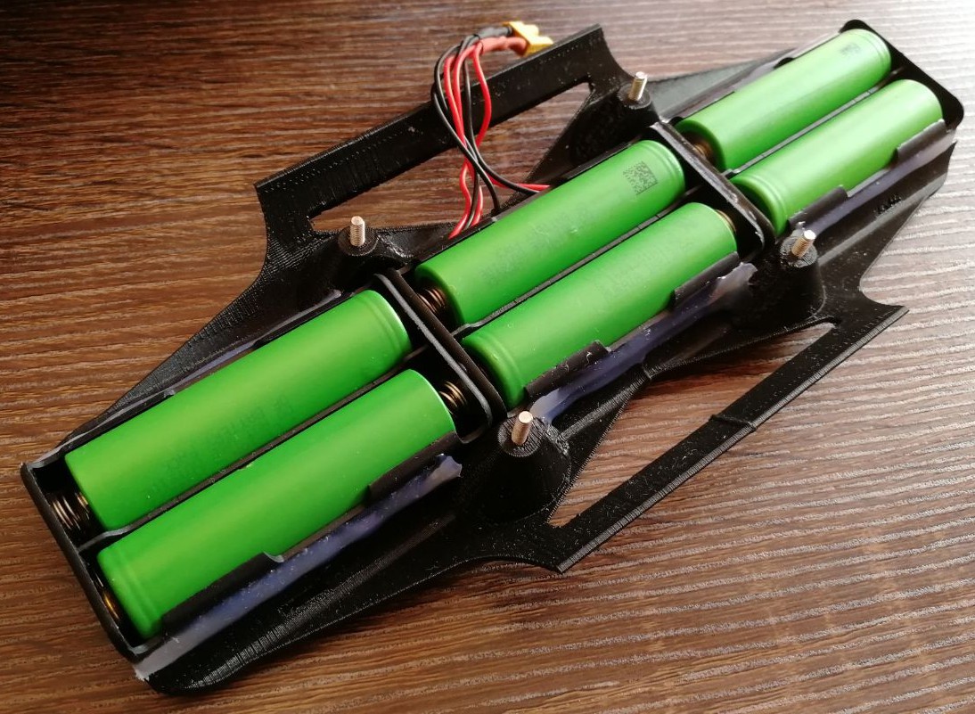
  • 3 × 2x 18650 battery holders in serie (7,4 V)
  • 20 × 8x3x4 mm bearings (autter x inner x width)
  • 1 × MPU6050 IMU. accelerometer + gyrocope.

View all 11 components

  • Improving the leg mechanism and new PCB board.

    Miguel Ayuso Parrilla11/01/2022 at 02:17 0 comments

    It's been a while since I don't update the project but it doesn't mean I've stopped working on the robot ;)

    About the code, there is still a very primivite version of the model at Github. I've been also improving it but still some cleaning up of the code needed as I want to show it clear to understand. Hope on next months it cound be done!

    You can check further updates on Instagram


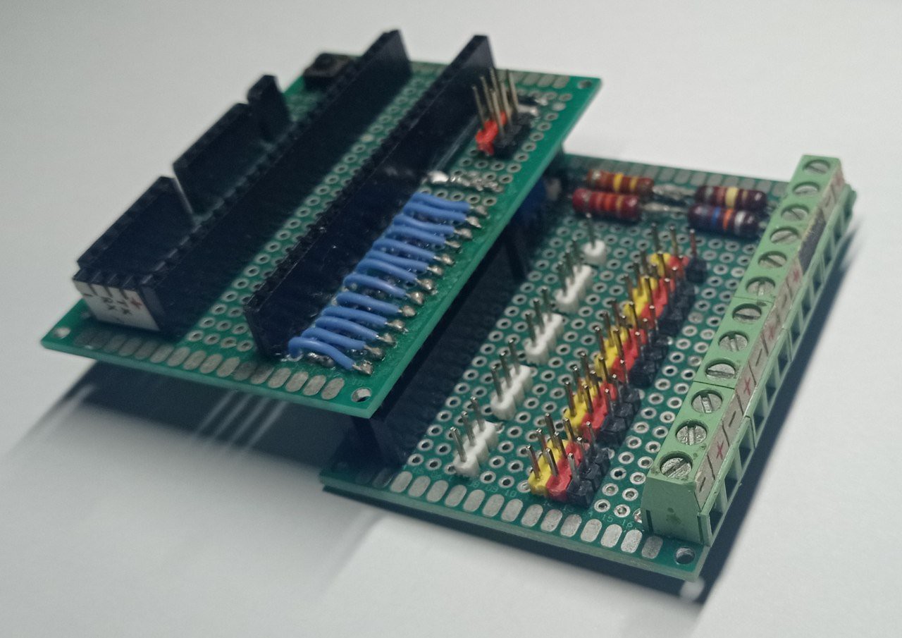
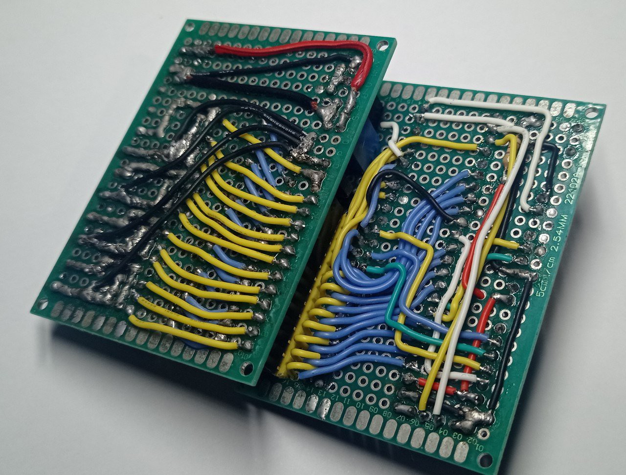
    Desinging a PCB board

    I want to share PCB I made to interface all conections. Making wiring by hand is always tedious and it can be cosidered like an art.

    But now is very easy to design and manufacture your own PCBs for a very small budget.

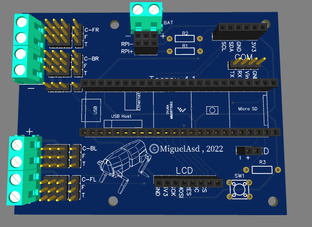
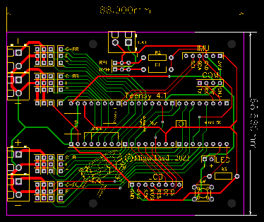
    The board is very simple and make the wiring job very straight forward. The carateristics are:

    • Teensy 4.1 interface. It is very fast, which can handle even LCD and achieve high frequency.
    • I2C bus for 9-DOF Absolute Orientation IMU, bno055 in my case.
    • Serial tx/rx and Vin to power Teensy.
    • 13 servo connections divided in 4 different power supply.
    • 13 analog input, in other to read each servo's potentiometer.
    • Voltage divider to read battery voltage.
    • 3V3 output.
    • Push button.

    ATTENTION!: If powering Teensy through 5V pin power supply, don't connect USB supply. As both voltage at the same time can damage microcontroller.

    Manufacture it is very easy now, Thanks to PCBway we get high quality PCB plus very good service, solving any manufacturing doubt very fast. It was very easy to order the boards!

    You can get PCB files here.


    ________________________________________________________________________________


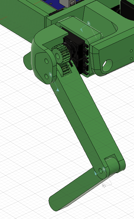
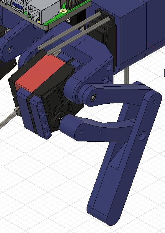
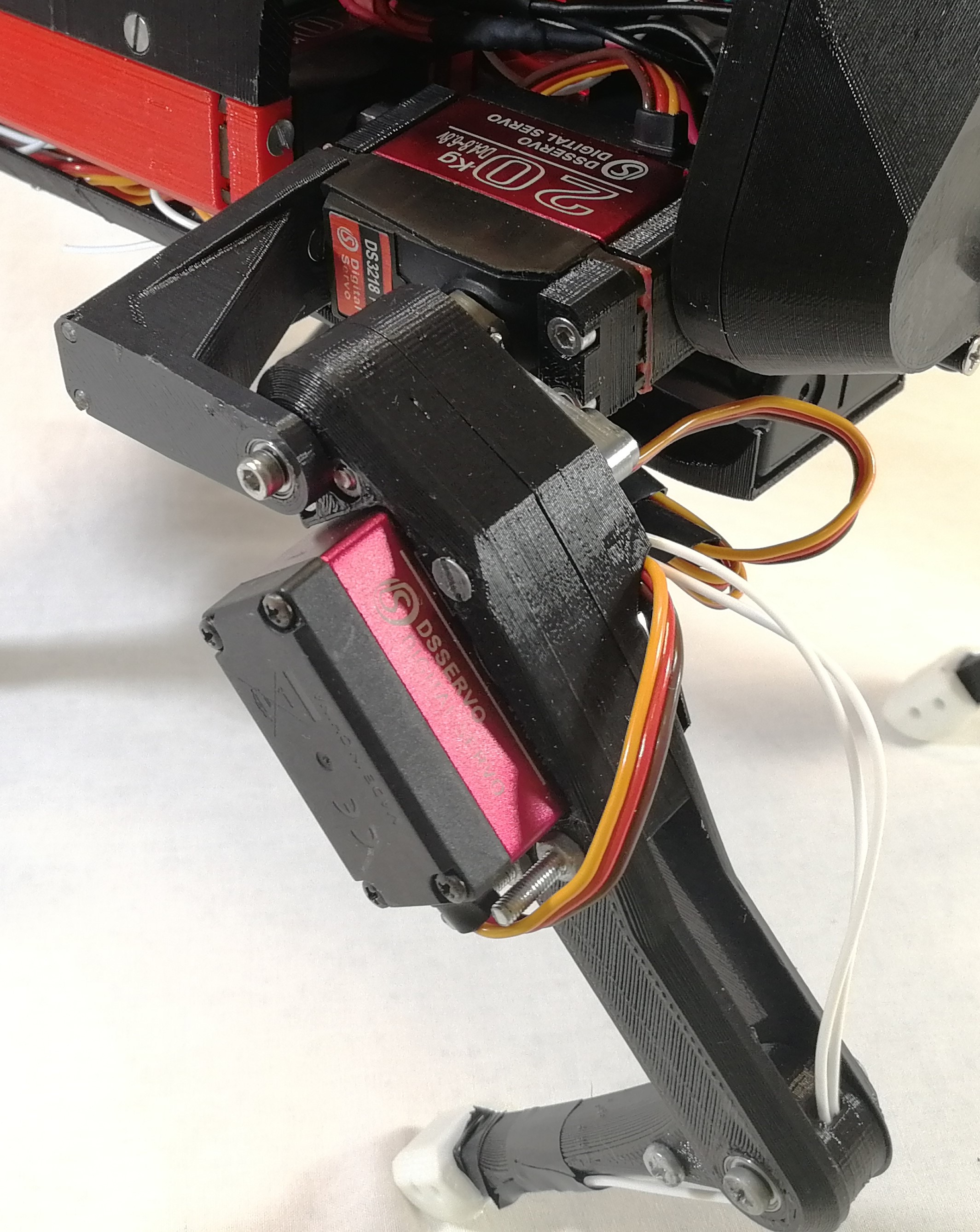
    Improving the leg mechanism.


    Along this 3 years I have been trying several leg mechanism.

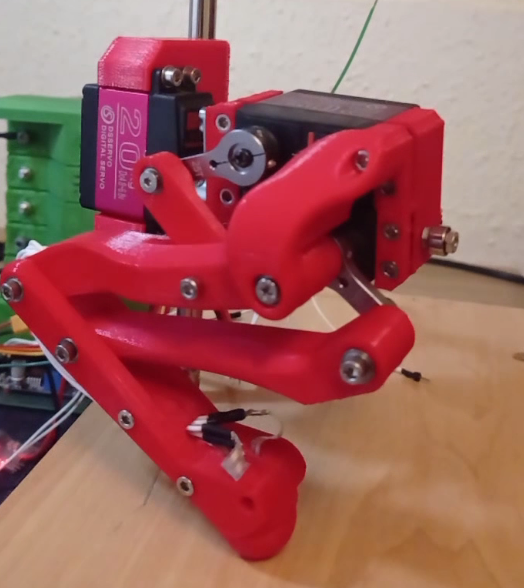
    Finally I decided to do a simple design with tibial motor placed on the femur joint.

    But this design still had several problems, like it wasn't very robust and the most importat is that having the motor (with big mass) that far from the rotating axis, caused in fast movements, unwanted dynamics to the robot body, making controlability worse.

    New version have both motors of femur/tibial limb at coxa frame, this ends with a very simple setup and at the same time, the heaviest masses of the mechanism are centered to the rotating axis of coxa limb, so even though the leg do fast movements, inertias won't be strong enough to affect the hole robot mass, achieving more agility.

    Inverse Kinematics of the mechanism

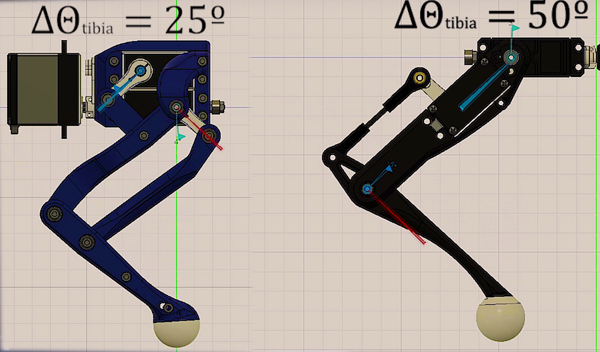
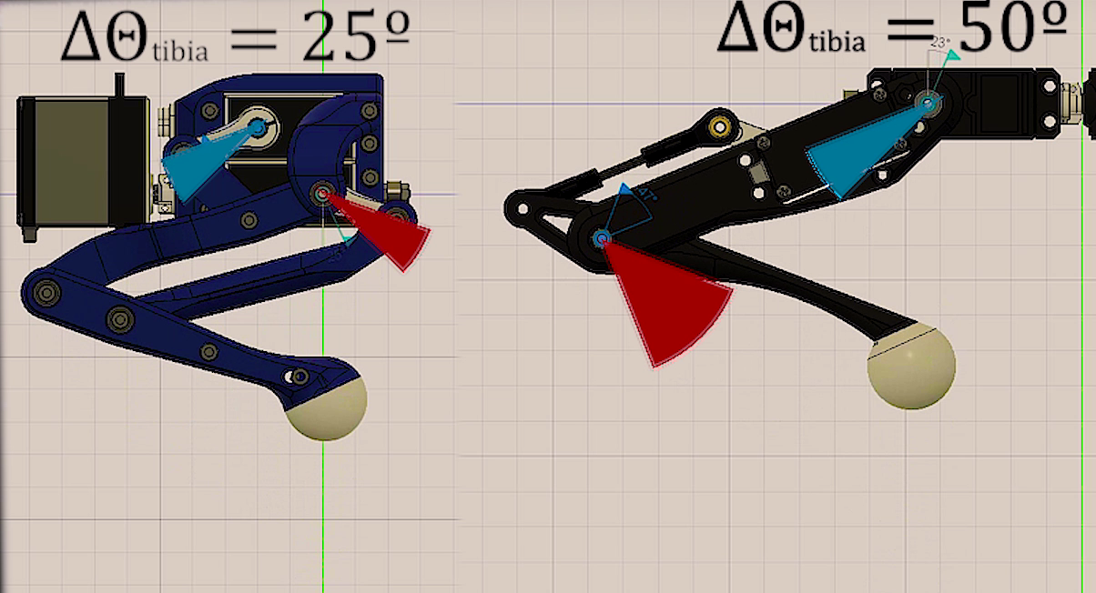
    After building it I notice that this mechanism was very special for another reason, at the domain the leg normally moves, it acts as a diferential mecanism, this means that torque is almost all the time shared between both motor of the longer limbs. That was an improvent since with the old mechanism tibial motor had to hold most of the weight and it was more forced than the one for femur.

    To visualize this, for the same movement, we can see how tibial motor must travel more arc of angel that the one on the new version.

    In order to solve this mechanism, just some trigonometry is needed. Combining both cosine and sine laws, we can obtain desired angle (the one between femur and tibia) with respect to the angle the motor must achieve.

    Observing these equations, with can notice that this angle (the one between femur and tibia) depends on both servos angles, which means both motors are contributing to the movement of the tibia.


    Calibration of servos

    Another useful thing to do if we want to control servo precisely is to print a calibration tool for our set up. As shown in the image below, in order to know where real angles are located, angle protactor is placer just in the origin of the rotating joint, and choosing 2 know angles we can match PWM signal to the real angles we want to manipulate simply doing a lineal relation between angles and PWM pulse length.

    Then a simple program in the serial console can be wrtten to let the user move the motor to the desired angle. This way the calibration process is only about placing motor at certain position...

    Read more »

  • New leg design.

    Miguel Ayuso Parrilla07/29/2022 at 12:20 4 comments

    This log is just to let all know that I'm still working on the robot. It's been quite a long time without any update (Studiying physics require must of my time this past years) but I've been doing some important progress on leg design and simulation.

    From now I'll be updating and producing more content about the robot. Stay tuned!

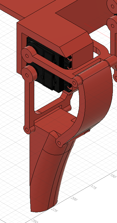
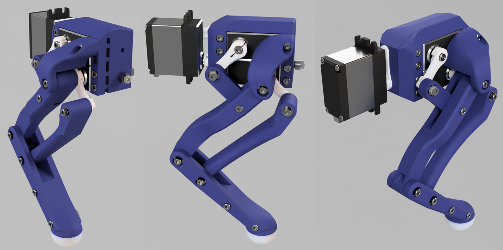
    Until then, to ilustrate what is coming, here a render of the new leg.

    Testings on this design have shown a quite remarkable improvement on performance.

  • Project bibliography and interesting papers.

    Miguel Ayuso Parrilla10/02/2020 at 13:42 0 comments
  • Small community.

    Miguel Ayuso Parrilla09/28/2020 at 15:32 3 comments

    This log is just to show the repercussion of the project and say thanks for the support from all of you that are reading this project.

    This is awesome to see that the hard work you made can be very useful for others. Even to the point of creating a new platform with a small community that is growing every day.

    This project has let me see the values of the OPEN SOURCE community, how easy is nowadays to develop a new platform, each contributor from very different places in the word but with one commun interest that is learn things in order to make our lives more interesting.

    Here are some of Makers that supported the project since the first day and they already have a small Chop at their homes:

    Thanks to @OilSpigot 

    (min 4:00 to see his robot in action)

    Thanks to @Creasento:


  • Bill of materials and price of the robot.

    Miguel Ayuso Parrilla09/19/2020 at 12:33 0 comments

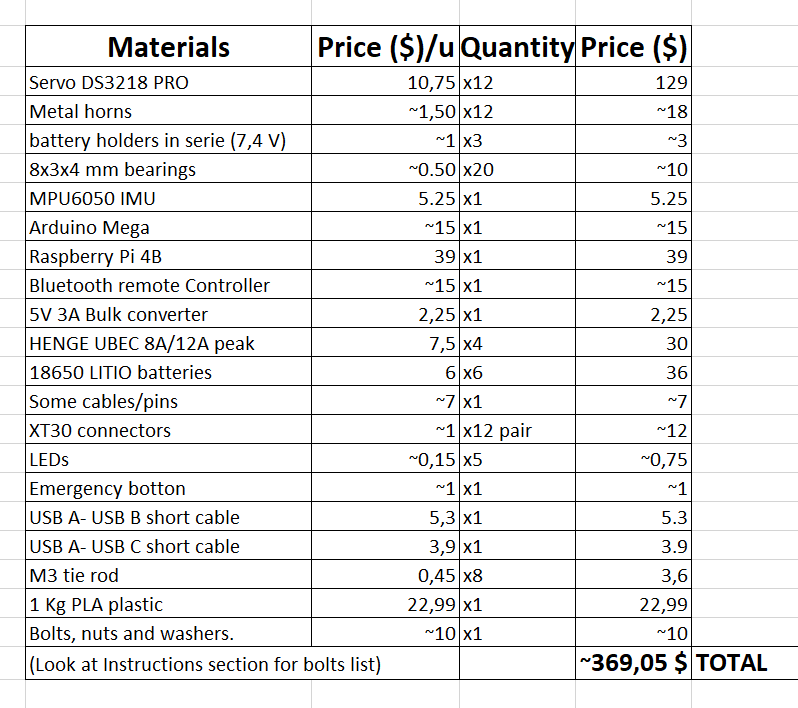
    To complete the Component Section, in this log i want to show the complete bill of materials, with the price for one unit of the robot, i have to say i'm surprised how cheap it is to build just one robot.

    In my case, this development has been more expensive as i have made 3 different prototypes with its resvective components, so more or less i have spent two times the price of one unit.

    Almost all componet were bought from the typical chenese online wareshops.

    Once you have all the components, the building procress is not very hard if you have experience with 3D printed prototyping.

    Go to Instruction Section

  • PyBullet Simulation example

    Miguel Ayuso Parrilla09/15/2020 at 13:06 0 comments

    This log i'm going to talk about the simulation used for the robot development, this was mostly used for debugging the maths inside the the different models.

    The code of the simulation is no longer implemented in the Raspberry code, as it can't support GUI mode and i'm not taking data from PyBullet environment. The code i am referring to is at the V1_PCsimulation branch of the robot GitHub repository.


    This code can be ran with the robot just plugging the arduino to the PC via USB and run the robot_walking.py file, all requirements at README.md

    But if you don't have the robot built, you can run just the simulation a play along with the robot inside the PyBullet environment. Also feel free to modify it and improve it.

    You just need PyBullet and Numpy on Python 3, then download the V1_PCsimulation branch and run walking_simulation_example.py.

    More info of how the simulation works shown in the next video:


    Now, i'm going to breightly explain the main code of the simulation, here is shown:

    """
    Created on Sun Mar 15 19:51:40 2020
    @author: linux-asd
    """
    
    import pybullet as p
    import numpy as np
    import time
    import pybullet_data
    from pybullet_debuger import pybulletDebug  
    from kinematic_model import robotKinematics
    from gaitPlanner import trotGait
    
    """Connect to rhe physics client, you can choose GUI or DIRECT mode"""
    physicsClient = p.connect(p.GUI)#or p.DIRECT for non-graphical version
    p.setAdditionalSearchPath(pybullet_data.getDataPath()) #optionally
    """set Gravity"""
    p.setGravity(0,0,-9.8)
    
    """import the robot's URDF file, if it is fixed no ground plane is needed""" 
    cubeStartPos = [0,0,0.2]
    FixedBase = False #if fixed no plane is imported
    if (FixedBase == False):
        p.loadURDF("plane.urdf")
    boxId = p.loadURDF("4leggedRobot.urdf",cubeStartPos, useFixedBase=FixedBase)
    
    jointIds = []
    paramIds = [] 
    time.sleep(0.5)
    """get info along all the joints for debugging if needed"""
    for j in range(p.getNumJoints(boxId)):
    #    p.changeDynamics(boxId, j, linearDamping=0, angularDamping=0)
        info = p.getJointInfo(boxId, j)
        print(info)
        jointName = info[1]
        jointType = info[2]
        jointIds.append(j)
        
    footFR_index = 3
    footFL_index = 7
    footBR_index = 11
    footBL_index = 15   
    
    """init the classes used"""
    pybulletDebug = pybulletDebug()
    robotKinematics = robotKinematics()
    trot = trotGait() 
    
    #robot properties
    """initial foot position"""
    #foot separation (Ydist = 0.16 -> tetta=0) and distance to floor
    Xdist = 0.20
    Ydist = 0.15
    height = 0.15
    """This matrix will define where the feet are going to be at its standing position
    with respect the center of the robot"""
    #body frame to foot frame vector
    bodytoFeet0 = np.matrix([[ Xdist/2 , -Ydist/2 , -height],
                             [ Xdist/2 ,  Ydist/2 , -height],
                             [-Xdist/2 , -Ydist/2 , -height],
                             [-Xdist/2 ,  Ydist/2 , -height]])
    """Gait definition parameters, here you can set different period of step and
    the offset between every foot's loop, defining different gaits"""
    T = 0.5 #period of time (in seconds) of every step
    offset = np.array([0.5 , 0. , 0. , 0.5]) #defines the offset between each foot step in this order (FR,FL,BR,BL)
    
    """start a real time simulation, so no simulation steps are needed"""
    p.setRealTimeSimulation(1)
        
    while(True):
        lastTime = time.time()
    """show sliders in the GUI"""
        pos , orn , L , angle , Lrot , T = pybulletDebug.cam_and_robotstates(boxId)  
        #calculates the feet coord for gait, defining length of the step and direction (0º -> forward; 180º -> backward)
        bodytoFeet = trot.loop(L , angle , Lrot , T , offset , bodytoFeet0)
    
    #####################################################################################
    #####   kinematics Model: Input body orientation, deviation and foot position    ####
    #####   and get the angles, neccesary to reach that position, for every joint    ####
        FR_angles, FL_angles, BR_angles, BL_angles , transformedBodytoFeet = robotKinematics.solve(orn , pos , bodytoFeet)
         
    """move all joints at the next time step angle"""
        #move movable joints
        for i in range(0, footFR_index):
     p.setJointMotorControl2(boxId,...
    Read more »

  • Future 3DoF foot sensor.

    Miguel Ayuso Parrilla08/27/2020 at 20:52 0 comments

    In order to make the robot dynamic in the precisse meaning of the word, we need to have meassurements of the forces acting acting inside the robot, this can be either from the actuators, feet or the IMU.

    This way we can build a robust control algorithm taking into account these forces, such as the Inverse Pendulum model. Basically what we want in here is to implement a physics math model in stead of a direct model like the Kinematics model it implements now.

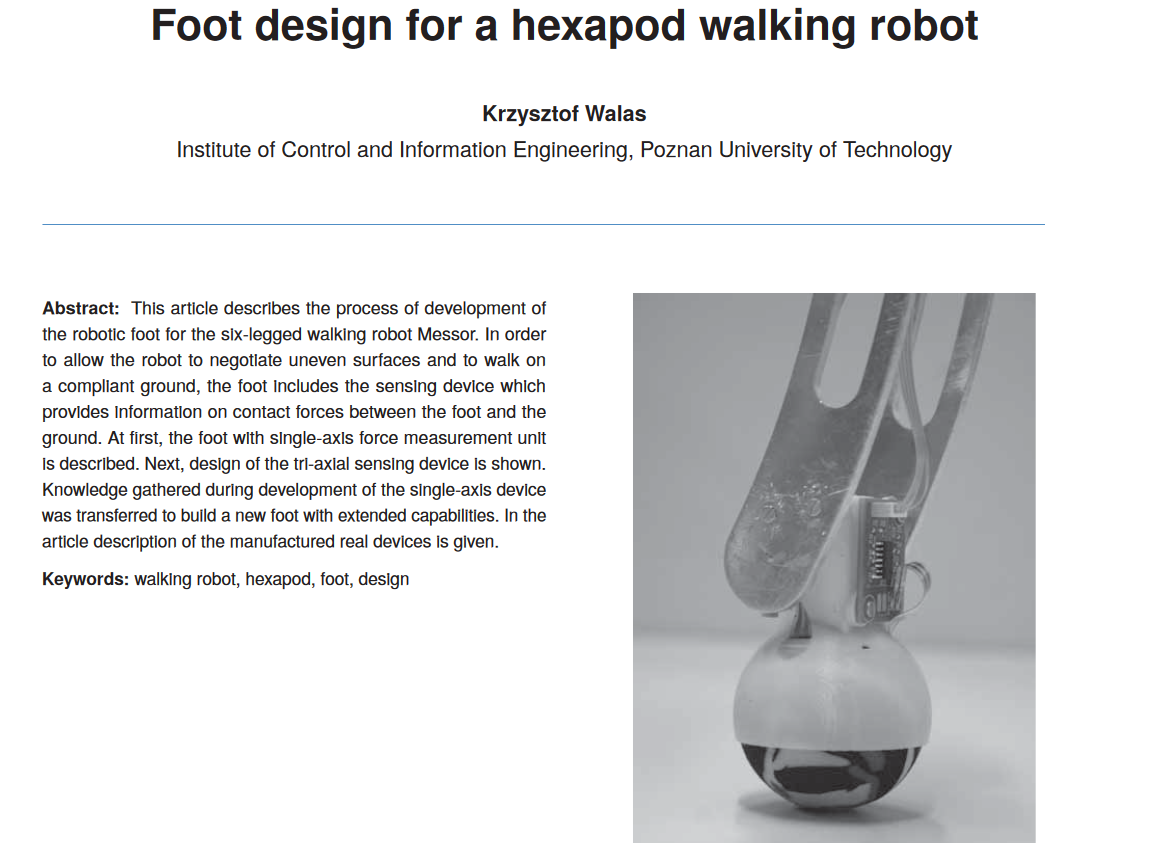
    This task is not easy to achive, but i found a paper with a very inteligent solution to this problem: Foot design for a hexapod walking robot.

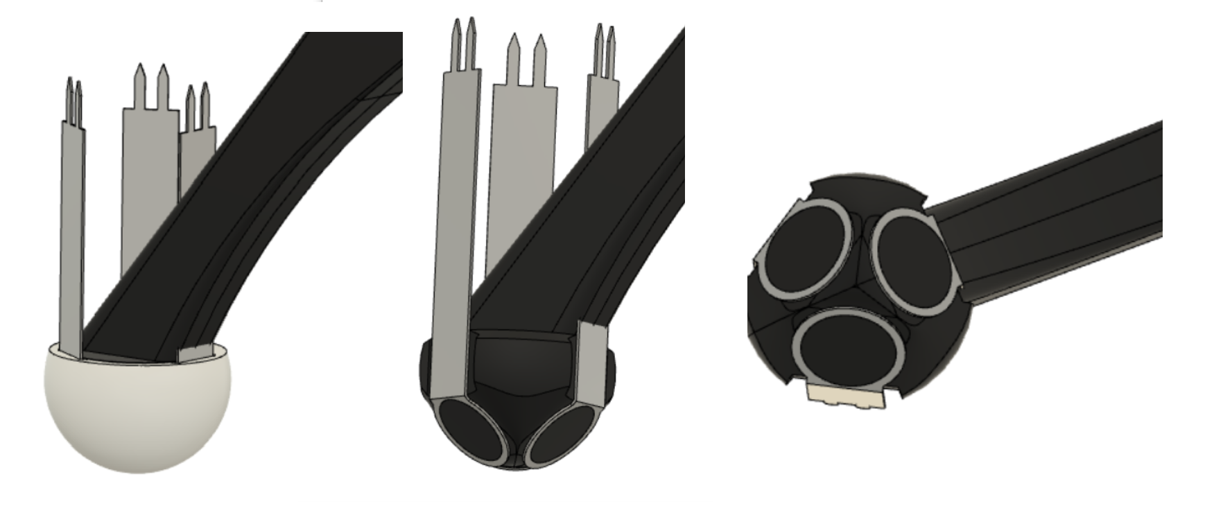
    Basically it uses 3 sensitive resistance force sensor, with a proper orientation in order to read the forces at the foot in the 3 different directions.

    What i came with is shown in this pictures, but this is only a quick design with lot of errors at the time of reading accurate meassurements.


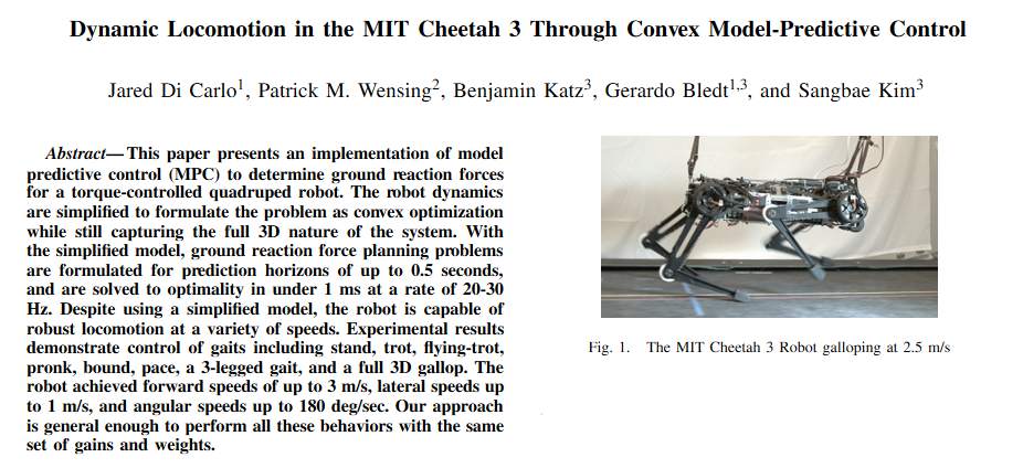
    Some actual works on the MIT cheetah show how usefull can be this type of foot sensor:

  • Calibrating the servos.

    Miguel Ayuso Parrilla08/01/2020 at 09:15 0 comments

    First of all, you will need to plug all servos to their proper pin, in my case here they are (you can change this for your how setup):

    void connectServos() {
                          //FR
      Servos[0].attach(40); //coxa
      Servos[1].attach(38); //femur
      Servos[2].attach(36); //tibia
                          //FL
      Servos[3].attach(42); //coxa
      Servos[4].attach(44); //femur
      Servos[5].attach(46); //tibia
                         //BR
      Servos[6].attach(34); //coxa
      Servos[7].attach(32); //femur
      Servos[8].attach(30); //tibia
                         //BL
      Servos[9].attach(48); //coxa
      Servos[10].attach(50); //femur
      Servos[11].attach(52); //tibia
    }

    As soon as the servos are corretly attached, what i made in order to put the servos on its correct position is just to dissasembly the legs, i mean, separate the servo output from the its horn, in order to let the servo move freely. This way you can power the servos, let them go to the zero position and the reassembly.

    I wrote a small sketch in order to put the servos on their zero position, you can find it at servo_calibration.py file, this way you can attatch the servo very close to their zero position.

    Then, a more precise calibration is needed, you will need to calibrate the offset of each servo, those offset are defined at angleToPulse.py file. This file only contains the line defining the pulse corresponding to each angle for every servo.

    Being a line in the form: y = Ax + B. The offset of each servo is defined by B, which mean the pulse at the zero angle.

    If you are using different servos, the slope of the line (A) will be different so you will need to identify it. What i did, is just to take 4-5 meassurement of pulse at different angles and put them on an excel where i calculate the adjucted line from those points.

    def convert(FR_angles, FL_angles, BR_angles, BL_angles):
        pulse = np.empty([12])
        #FR
        pulse[0] = int(-10.822 * np.rad2deg(-FR_angles[0])) + 950
        pulse[1] = int(-10.822 * np.rad2deg(FR_angles[1])) + 2280
        pulse[2] = int(10.822 * (np.rad2deg(FR_angles[2]) + 90)) + 1000
        #FL
        pulse[3] = int(10.822 * np.rad2deg(FL_angles[0])) + 1020 
        pulse[4] = int(10.822 * np.rad2deg(FL_angles[1])) + 570
        pulse[5] = int(-10.822 * (np.rad2deg(FL_angles[2]) + 90)) + 1150
        #BR
        pulse[6] = int(10.822 * np.rad2deg(-BR_angles[0])) + 1060 
        pulse[7] = int(-10.822 * np.rad2deg(BR_angles[1])) + 2335 
        pulse[8] = int(10.822 * (np.rad2deg(BR_angles[2]) + 90)) + 1200
        #BL
        pulse[9] = int(-10.822 * np.rad2deg(BL_angles[0])) + 890
        pulse[10] = int(10.822 * np.rad2deg(BL_angles[1])) + 710
        pulse[11] = int(-10.822 * (np.rad2deg(BL_angles[2]) + 90)) + 1050
        return pulse

  • A more stable walking.

    Miguel Ayuso Parrilla07/20/2020 at 11:49 0 comments

    This log is about polishing the gaitPlanner as you can see in the next video:


    What is interesting on this video is that no control algorithm is running, but it seems very stable.

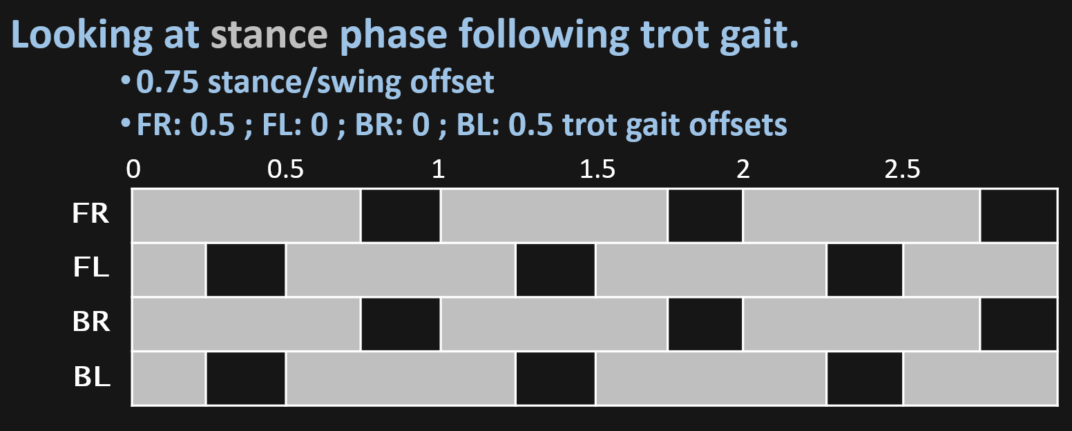
    This is achived just by separating stance phase from the swing (as explained in the gaitPlanner.py log), this way i can define an offset between both phases, so running the stance phase at 3/4 of the hole step, makes the robot to hold its weigth on the 4 legs for a short period of time being a bit more stable, just by running the gaitPlanner loop.
    Visually the gait is defined like follows:

    Aditional info about that is that servos got very hot if it runs for more than 10 minutes.

  • Quadruped robot meets my cat.

    Miguel Ayuso Parrilla07/07/2020 at 18:29 0 comments

    As a quick update of the V2 robot performing i have introduced it to my cat.

    My cat is very introverted and usually doesn't like new things, in this case isn't different but it seems to cause she some curiosity.

    The robot performs well, as it uses the last version of the code, the extra weigth of the batteries and raspberry pi is not a problem as the new design is much more lighter and the servos are now powered at 6V in stead of 5V as in the first version.

    On the other hand, i have notice the model randomly gives bad solutions running on the raspberry pi, thats why sometimes you see the leg make a strange movement. I haven't identify the problem yet, maybe is my software problem or bufer overflow.

    There is no aim to hurt the animal, is my cat omg.

View all 17 project logs

  • 1
    Building premises.

    I'm going to enumerate some important concepts i have taken into account for the robot design.

    • This robots depends hardly on its mass distribution and dynamics of the moving parts (legs). Thats why i decided to go for this servo configuration, having the coxa servo on the body, the femur servo on the coxa and tibia servo on the the femur, so there is only 2 servos moving with the legs.
    • This way, the less leg weight the less unexpected inertia, causing a better dynamic behavior.
    • Also the robot weight should be as less as posible becouse hobby servos can be overcharged easily.
    • About the mass distribution, this would define the Center of Mass which should be the closest to the Geometric Center, for this the building must be as simetric as posible, this way CoM is easier to locate and the control would be more predictable.
    • The lenght of the leg is defined at 100 mm for both tibia a femur, this way, a motor with 20 Kg/cm will hold 2 kg at a 10 cm arm. So the longer the arm, the less force the motor can support.
    • Avoid plastic vs plastic joints, this would involve unnecessary friction forces.

    Printing premises.

    • This is simple but is important to take this into account, at the time of printing, these parts are not supporting much mechanical forces, for this and taking into account building premises, the 3D printed parts should be printed with ~10-20% infill , 1-2 outer perimeters and 2-3 solid layers.
  • 2
    Building and printing the robot.

    For building this i have made this tutorial, as there are some tricky parts.

    In the file section, each STL is named with the quantity of parts you need to print, if none just one needs to be printed.

    Also you can download files all at once at the file section, file STL_files.zip.

    If you are building the robot, take into account this: 

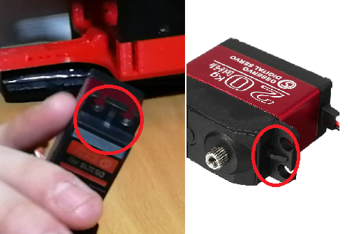
    Some servos has a small ridge in the holding holes for making this part stronger, for my desing i did cut these small ridges in order to make the parts easier to print and design.


    Bolt list:

    • M3 x45 mm: quantity 12
    • M3 x30 mm: quantity 26
    • M3 x25 mm: quantity 16
    • M3 x20 mm: quantity 8
    • M3 x15 mm: quantity 16
    • M3 x7 mm: quantity 4
    • M3 threaded rod x 42 mm: quantity 4
    • M3 threaded rod x 74 mm: quantity 8

    Plus its respectives nuts and washers where is needed.

  • 3
    Electronics.

    Here is the electronics setup i have:

    You can download the full size PDF file of the scheme at the file section.

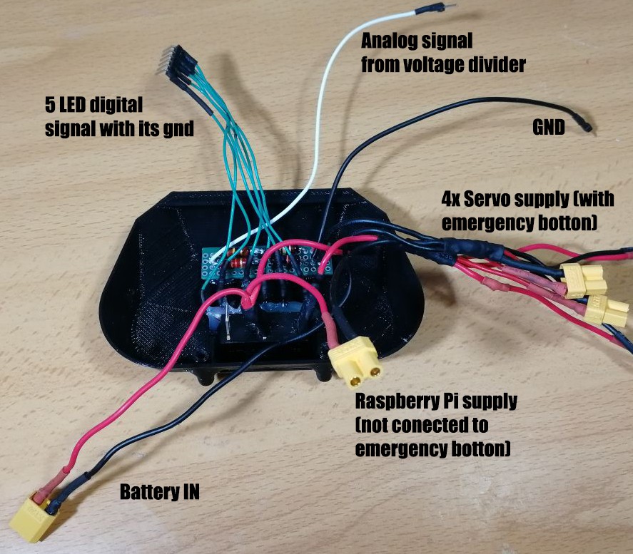
    As you can see, appart from the 4 power lines in order to power the servomotors, there is also a voltage divider in order to read the batterie voltage in the arduino from an analog pin and then 5 LEDs will indicate the batterie status. Finally, IMU is connected via I2C interface. Raspberry pi is powered via another bulk converter at 5V 3A, that i miss (i will correct this in the next updates) and arduino communicates via USB cable (which also power it) to raspberry pi.

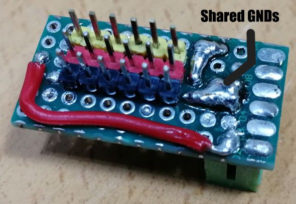
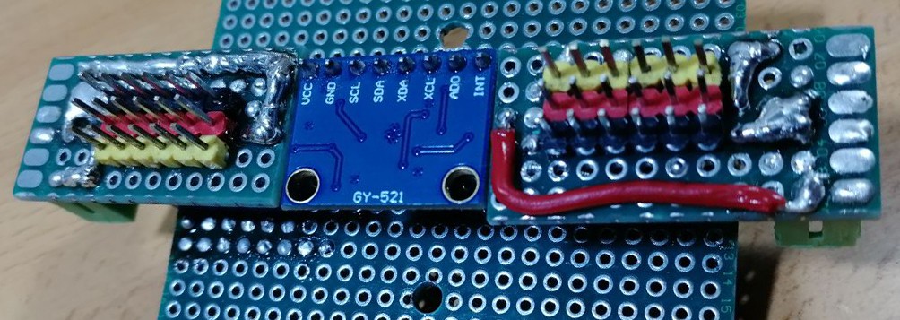
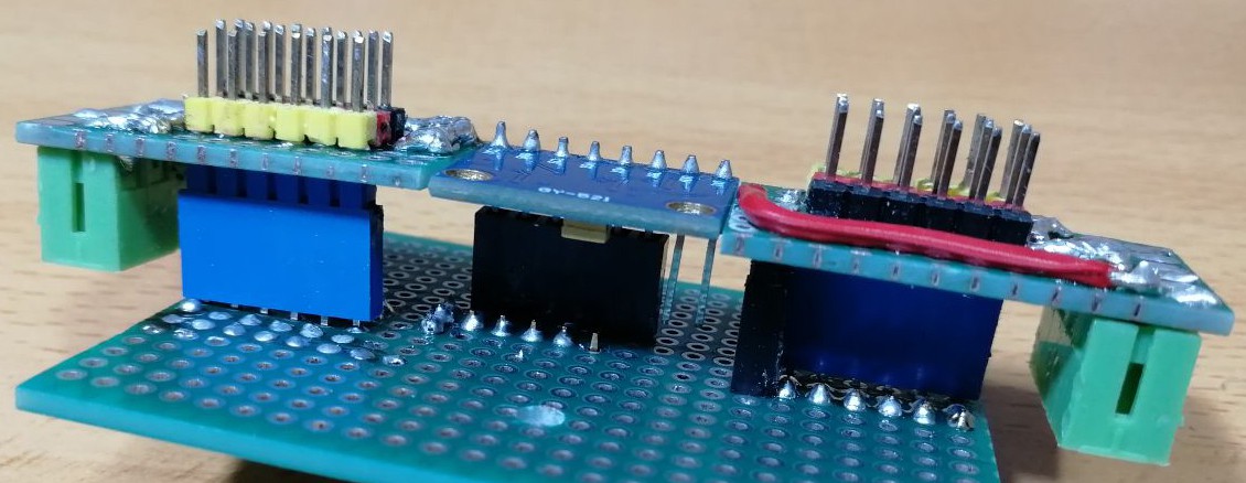
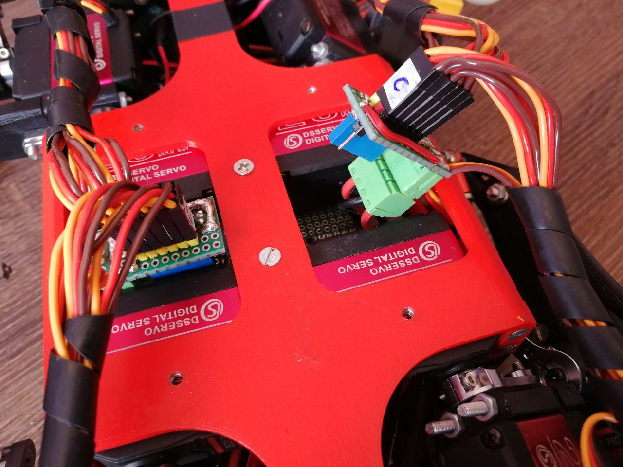
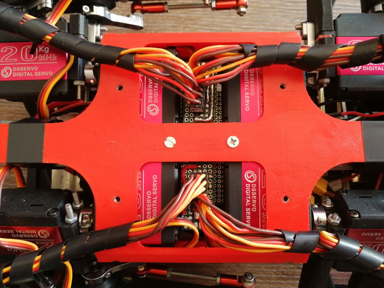
    I made two modular small boards in order to easily connect and disconnect servos, these boards are conected to the big one, which will supply all the pins to the arduino, being the 12 pwm signals with its commun ground and the I2C interface for the IMU. Also here, i can add sensors (FRS) the same way for the future.

    Details of the building:

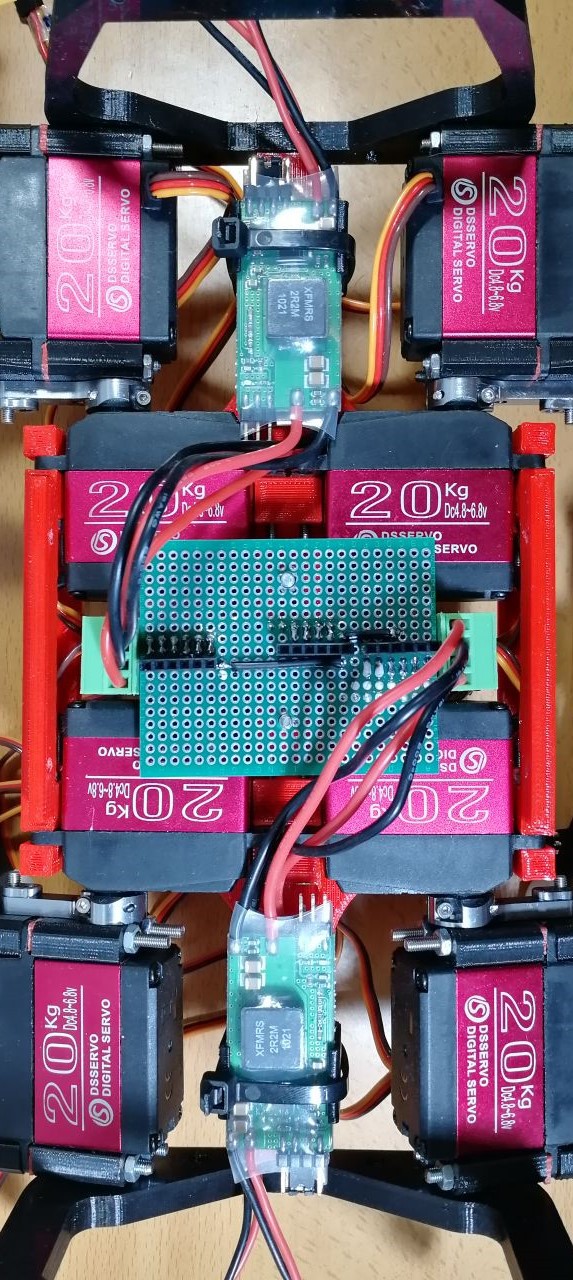
    • Starting from the small board that supplies the servo power and the digital signal for the arduino, they have shared GNDs and are divided into 4 different lines, one for each bulk converter. They are connected to the main board, which accommodates the IMU and two of these boards.
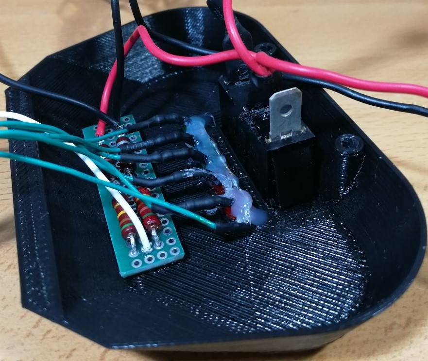
    • The other components that accomodates some electronics is the back cover of the robot, where the Emergency Botton is placed along with the 5-LED battery indicator, also the voltage divider in orther to read the battery voltage is placed here, attached with some hot glue.
    • Finally everything is prepared to be mount, notice that bulk converters are placed between the fermur servos and attached with tape. Also, you can see how Raspberry Pi and Arduino MEGA are attached to the top of the robot.
    • Finally, the battery is made with individual cells, so i have to charge them one by one.

View all 3 instructions

Enjoy this project?

Share

Discussions

OilSpigot wrote 08/04/2020 at 07:32 point

I made some robot shoes out of foam and rubber that have greatly improved traction on wood floors. I'll test them out on a couple other surfaces this week. Let me know if you want a pair and I can mail them to you as a thanks for putting out all this great info.

https://www.youtube.com/watch?v=KT2_h3yJYxA&feature=youtu.be

I have some comments for the code: 

In robot_main_RPI.py, T is defined as the step period, but it is redefined in src/joystick.py that overwrites the value. So if you want to change T you have to do it in joystick.py

If I change height will this have the effect of raising the robot up 4 cm?

Xdist = 0.25

height = 0.16 #increase to 0.20

#body frame to foot frame vector (0.08/-0.11 , -0.07 , -height)

Also, I may want to experiment with changing the bezier curve. Do I just change these values in gaitPlanner.py with help from https://www.desmos.com/calculator/xlpbe9bgll?

X = np.abs(V)*c*np.array([-0.05 ,-0.06 ,-0.07 , -0.07 ,0. ,0. , 0.07 ,0.07 ,.06 ,0.05 ])

Y = np.abs(V)*s*np.array([ 0.05 ,0.06 ,.07 , 0.07 ,0. ,-0. , -0.07 ,0.07 ,-0.06 ,-0.05 ])

Z = np.abs(V)*np.array([0. ,0. ,0.05 , 0.05 ,.05 ,0.06 , 0.06 ,0.06 ,0. ,0. ])

I changed some of the values and it caused the program to crash, so i'm wondering if I did something like assign the leg to an out of bounds position. Might be nice to have a way to round out of bounds coordinate values to the nearest in-bounds point.

  Are you sure? yes | no

Miguel Ayuso Parrilla wrote 08/06/2020 at 16:38 point
Hi man! As you asking very in deep question, we can told easier at the public chat of the project, this way we don't overflow the comments section.

Nice shoes man, but i have redesigned them for having more grip but maybe a solution like that will be needed as TPU isn't as grippy as gum.

The code: yes T is redefined, this is just to show that T must be defined but the one that is used is at joystick.py, i'll write a log showing the bottons used and what they do, as T can by changed with right-left arrows.

You are right with redifining the heigh, as those dimentions are the definition of initial position of CenterToFoot vectors, be careful as 20cm in some cases is not reacheable, you can see in the console when one position of IK is out of blounds it prints __OUT OF DOMAIN__ (this means there is a NaN solution at the IKs and last real solution is used), so you can try the limits empirically.

About the gait trajectory i don't really recommend you changing it as you can see in the olders code versions, the best i have tried is the MIT one, anyway, yes there is where the bezier points are defined, you can see the drawing at that page.

  Are you sure? yes | no

OilSpigot wrote 08/02/2020 at 06:01 point

Can you give me some pointers on if I did the calibration correctly? It tends to fall forward over its front legs when I walk forward or backwards.

https://www.youtube.com/watch?v=h2wGVGGim3o

Thank you for putting this page together, I have learned a ton so far.

  Are you sure? yes | no

Miguel Ayuso Parrilla wrote 08/02/2020 at 10:17 point
It seems the calibrarion is good but now you have to precisly calibrate it, what version of code are you running? I always recommend to run my last code version at github as it would be the most stable one. Are you running it on raspberry pi? Check last log and the calibration file, what i did for precise calibration, with a bubble level and putting the joints at zero position, difine each offset at the angleToPulse.py. On the calibration file you can also define other angles in order to check of the calibration is correct. Here, for going a bit faster i was adding a variable to the offset, adding +-10 microseconds each time click a botton on the joystick controller, finally printing the new offset. I'll explain this in details in some days with more visual explanatios of the calibrarion.

About the video, it seems really nice but there are some power supply problems, at some times there is a tibia that is not even powered.

  Are you sure? yes | no

OilSpigot wrote 07/24/2020 at 17:33 point

Finished printing most of the parts and i'm now moving on to electronics.

https://hackaday.io/project/173974/gallery#5505dbf9dcb2f21484781965f23c5154

Why do you use 4x Bulk converter boards? They can do 12A each, which should be enough to power the robot using 1.

Could I use some 500F ultracapacitors to buffer the output instead?

  Are you sure? yes | no

Miguel Ayuso Parrilla wrote 07/25/2020 at 08:11 point
Wow!! That's really nice man!! During the next weeks i'm upgrading the tibia as background renders suggest. You will notice, the actual tibia setup makes the redirect forces to a weak point at the femur.

About the power comsution, i have calculated 3Amps peak for each servo thats why i have chosen 4 of them, also i will upgrade to bigger servos. Maybe 2 of them would be enough but i but this just to be sure it is safe.

About the supercapacitors, can't tell you, i haven't experimented with those.

  Are you sure? yes | no

Dan10110 wrote 07/26/2020 at 02:55 point

I am glad to hear the improvement. Right now, there aren't a lot of material around the hole at the femur. I will be waiting for it. Thanks

  Are you sure? yes | no

OilSpigot wrote 08/01/2020 at 01:24 point

I got all 12 servos plugged in and the RPI script running and responding to joystick inputs. It looks pretty funny right now, the arms are flailing in all different directions.

https://www.youtube.com/watch?v=8ugPX-Q6lbI

Can you make a diagram that shows which servo goes to which pin? I will need to do some calibrations, but its looking great so far.

I am interested in redesigning the legs, but want to use the software and electronics as a starting point.

  Are you sure? yes | no

OilSpigot wrote 08/01/2020 at 03:26 point

Just to follow up, I am using buck converter board to step the voltage down and it seems to be working. It is pushing about 10A to run all the motors, though there may be some cases where power draw goes above that amount.

  Are you sure? yes | no

Miguel Ayuso Parrilla wrote 08/01/2020 at 09:02 point

Hi man! You are so close to make it walk, there are just some points left i haven't had the time to explain.

I'll make a log on how to mount and the pin setup of the servos. I'm doing it right now.

So when you have already the servos on its correct pins. As you are using same servos, calibration would be the same, but you will need you adjust your own offset (explained at the new log), also as this servos doesn't have any mecanical stop, for calibrating i dissasembled all legs, then turn on the robot, so all servos goes to its position and then assembly the legs at their correct position. Maybe not the fastest way but worked really well for me. I'll share also the calibration script i used in order to put the servos to their zero angle.

About your powering... 10A wont be enough for walking, maybe 20/30A would be ok and for fast walking i recommend to go for the 48A setup. If servos doesn't have the power they need they can burn.

  Are you sure? yes | no

pjgrommit wrote 07/22/2020 at 20:51 point

Nice project.  I have built a spotmicro but there is no software.  Been looking at Stanfords pupper, but I like the idea of having an IMU.  Saw this the other day, reminded me of your bezier diagrams - https://youtu.be/FFS-2axFo1Y.  There's nothing new in the world. !

  Are you sure? yes | no

Dan10110 wrote 07/23/2020 at 04:44 point

Hi, I built the spotmirco too. It looks pretty nice and I got a lot of fun out of it. I got it walking using mike4192's SW from github. He has a very nice servo calibration procedure. I like Miquel's design because it reduces the weight and inertia issues. Spotmicro has all 3 servos in the leg and total weight of each leg including servos is about 300g(120+3x60). This causes some stability issue in motion unless you do a good job in static and dynamic balance. Pupper's design also addresses these issue but it is very expensive. I almost wanted to built it.

  Are you sure? yes | no

Miguel Ayuso Parrilla wrote 07/23/2020 at 09:32 point
About the software, as i'm at beginer level at programming, maybe my code will be a bit hard to tune and my calibration is made just by the hard way. Anyway, the calibration is done just by aproximating it to a line (representing angle vs pulse) so you can just write a simple sketch on arduino in order to identify that line, taking some point with an angle ruler and saving that pulses and then put it on the angletoPulse.py file, if it is done properly everything should work. I'll work for it to make it easier for you to calibrate the servos.

  Are you sure? yes | no

Miguel Ayuso Parrilla wrote 07/23/2020 at 09:21 point
Yeah maybe this gait is the more natural one, which as i have experimented this one is the most stable one.

  Are you sure? yes | no

Dan10110 wrote 07/21/2020 at 02:45 point

Hi, I appreciate you took the time to share your great project. It is a lot of work. I like your division of HW between Arduino and RPi. It makes a lot of sense for division of works to optimize CPU usage and power. Your partition of SW makes it easy to follow. I am in the process of building it. I have printed the 3 femur parts and found the ridge on servo mounting tab interferes with the inner femur. There seems to be no indentation to receive the ridge. Am I missing something? Thanks again.

  Are you sure? yes | no

Miguel Ayuso Parrilla wrote 07/21/2020 at 08:36 point

Thanks mate, this makes me so happy to know it is easy to follow along.

What servos are you using?

I did cut all the ridges from the servos with a cutter, sorry for that i forgot to notice that.

Also i want you to warn about the tibias, as i'm changing them, this change only affects to the tibia and the femur orientation, you can see it at the backgraund render. This change is because of how forces are distributed along the femur, so i need to flip the femur to solve that week point. Anyway this actual version works but there is a posibility of braking the femur.

Thanks for your comment and enjoy the build, feel free to ask what you need.

  Are you sure? yes | no

Dan10110 wrote 07/21/2020 at 22:00 point

Thanks for the clarification. I will remove the servo ridge. I plan to use PDI-HV5523MG servos as I have them from another project. Since they are HV, I can connect them directly to battery.  I really like your light weight design of the robot. As you know, high torque servos are expansive. Will let you know how my build goes.

  Are you sure? yes | no

Miguel Ayuso Parrilla wrote 07/21/2020 at 22:21 point
I reply here, as i can't reply your latest response.

About the servo ridge, if you won't cut them, you can just sand the 3d part with a small needle file.

Those servos are very nice, would be nice to try the design with diferent servos, hope there won't be dimension problems.

  Are you sure? yes | no

Sergio Gugliandolo wrote 07/19/2020 at 22:15 point

What have you used to prevent over-discharging or things like that for your batteries? Isn't it dangerous to use them without protection circuit?

  Are you sure? yes | no

Miguel Ayuso Parrilla wrote 07/19/2020 at 23:22 point
I chose quality batteries with quality protection circuit on each (SONY brand in my case) and appart from that i meassure the voltage in the arduino with a voltage divider and with 5 leds i display that meassurement, with that i don't let the batterie to go below 5'6 volts, which is when the last led is off.

  Are you sure? yes | no

OilSpigot wrote 07/15/2020 at 21:31 point

Great work. I plan on making one myself, just got a Raspberry Pi yesterday and am working through the several days worth of printing. 

I get an error when I try to run "walking_simulation_example.py" on the Raspberry Pi, saying "...GSLS 1.5 is not supported..."

Is that code supposed to be run on a computer, or can I run it on the Pi?

  Are you sure? yes | no

Miguel Ayuso Parrilla wrote 07/15/2020 at 22:35 point
This code was last ran on the pc, i have to update the code with my last version running on raspberry pi that doesn't need pybullet (becouse this error seems to be caused by the pybullet installation) as pybullet at GUI mode woudn't run properly.

Also in order to run "walking_simulation_example.py" you will need to specify the port of the arduino and the route of the controller's events

  Are you sure? yes | no

Miguel Ayuso Parrilla wrote 07/31/2020 at 18:55 point
New RPI code is updated, now it must run without problems on the Raspberry Pi, as long as you have all the libraries, plus arduino with its code and controller conected

  Are you sure? yes | no

Caleb wrote 07/12/2020 at 20:12 point

Do you cut the threaded rod to length (42 mm, 74 mm), or are you purchasing them in those lengths?

What washers are you using (as shown in the build video), what are the specifications?

  Are you sure? yes | no

Caleb wrote 07/12/2020 at 20:25 point

Sorry, not washers, bearings -- ball/flange bearings?

  Are you sure? yes | no

jbarrozo wrote 10/23/2020 at 02:11 point

same question

  Are you sure? yes | no

Miguel Ayuso Parrilla wrote 07/13/2020 at 08:58 point
I cut them, as i have the tools needed at home. About the bearings, as components sugest, they are the typical ball bearing with 3mm inner x 8mm outer x 4mm width.

Anyway Caleb, at this repo there is the STEP model, if you want to check bolt dimentions or what needed (this repo is from the awesome spot micro community, there is lot of research there): https://gitlab.com/Miguelasd/3dprinting/-/tree/master/User%20MiguelAsd%20custom%20models

  Are you sure? yes | no

Caleb wrote 07/07/2020 at 04:02 point

Where are the batteries in the V2 design -- is that the red underbelly area?

  Are you sure? yes | no

Miguel Ayuso Parrilla wrote 07/07/2020 at 15:20 point

Just under the body, you can check how it goes at the building video

  Are you sure? yes | no

Nicola Russo wrote 07/05/2020 at 14:10 point

Hello! I just want to let you know that your project largely inspired the kinematics model for my experiment (https://github.com/nicrusso7/rex-gym). Of course I've put your name and the link to this project in the credits section. Hopefully I can inspire you as well! :)

Well done!!

  Are you sure? yes | no

Miguel Ayuso Parrilla wrote 07/06/2020 at 12:39 point
Hi Nicola. This is amazing!! Your project is also very well documented, i will take a look at it! I'm happy to know it has been useful for you and thanks for spending your time reading my project. Together we are building something very big!

Regards.

  Are you sure? yes | no

dev1122 wrote 07/02/2020 at 16:12 point

what is the use of kinematic_model.py file, please help regarding that.

  Are you sure? yes | no

Chamika Ekanayaka wrote 06/29/2020 at 21:35 point

Hey there! Good job on the project, I was wondering if I could replicate this whole system, but I couldn't find any files for the 3D parts or any schematics to follow up, would these ever be available and how long would it take?

  Are you sure? yes | no

Miguel Ayuso Parrilla wrote 07/02/2020 at 15:47 point
I'm just working on it! i promise you to release all the 3d model files in 2 weeks max, i have just finished printing the final version and i'm starting to documentate all the building process, stay tuned man!

  Are you sure? yes | no

Alan Churichi wrote 06/20/2020 at 18:04 point

Hi! Really nice work!

Do you have schematics files for the connections?

  Are you sure? yes | no

Miguel Ayuso Parrilla wrote 06/21/2020 at 21:01 point
Thanks Alan! I'm working on it, as soon as i solder the new electronics i will post the schematics.

  Are you sure? yes | no

albertson.chris wrote 05/15/2020 at 00:40 point

Will you post th CAD files?   Already I'd like to try building just one leg for testing and I can think of a few changes.

One other question:  It looks like the prototype in the video was missing the Pi and batteries.  How much weight could be added?   Certainly the Pi4, batteries and see DC/DC regulator will need to be addd but also some sensors.

  Are you sure? yes | no

Miguel Ayuso Parrilla wrote 05/15/2020 at 10:07 point
Yes! i'm finishing them, i think in the next 3 month i will print all the parts left, correct them if there are mistakes and then share them.

Yes, batteries, raspi and its cables are taken into account in the design, they add about 500-700 g, but also i'm removing weight in the design. Another diference between prototype and wireless version is that cable is going at 5V and batteries at 7.4V.

So i think, there will be no problem with this extra weight

  Are you sure? yes | no

Mustafa wrote 05/14/2020 at 18:11 point

If you prepare a basic udemy course we can buy it

  Are you sure? yes | no

Mustafa wrote 05/14/2020 at 16:50 point

Miguel I am following your project, thanks for those precious informations.. Please continue..

  Are you sure? yes | no

Miguel Ayuso Parrilla wrote 05/15/2020 at 10:08 point
Thanks a lot man! Of course i'll be documenting all the project.

  Are you sure? yes | no

Comedicles wrote 05/14/2020 at 06:17 point

Does it have accelerometers and inertial orientation? Put the poor thing out of its misery and place it on a  rubber surface so that leg motion can correspond to movement through space. I can tell it is miserable!

  Are you sure? yes | no

Steve wrote 05/13/2020 at 17:23 point

I loaded the STLs into Ideamaker(3D-printer slicer) and it shows up super-tiny, like it's in inches not millimeters. What are the dimensions supposed to be  if we wanted to print this out ?
Thanks

  Are you sure? yes | no

Miguel Ayuso Parrilla wrote 05/13/2020 at 22:40 point

Those files are not printable, are only for show them on the simulation, thats why u see them very small as they are meassured on meters. If you look closer to them, there is no way to build or mount them with the hardware

  Are you sure? yes | no

Steve wrote 05/14/2020 at 00:10 point

Is there a way to print it out if we wanted to work on one ourselves or is that not ready yet ?

  Are you sure? yes | no

Steve wrote 05/14/2020 at 00:14 point

Anyway, this is still very cool and I'm looking forward to reading about it more as it progresses along.

  Are you sure? yes | no

Alior101 wrote 05/13/2020 at 16:34 point

Cool! Is this the 180 or 270 pro version of  DS3218?

  Are you sure? yes | no

Miguel Ayuso Parrilla wrote 05/13/2020 at 17:17 point

180 PRO version, as for example, the tibia movement is limited to 110 dregrees.

  Are you sure? yes | no

Alex Tacescu wrote 05/13/2020 at 15:58 point

Super cool project! Are you calculating forward/inverse kinematics on the Arduino? Or is everything done in the physics engine?

  Are you sure? yes | no

Miguel Ayuso Parrilla wrote 05/13/2020 at 17:21 point
I'm calculating them on the python sketch in the computer/raspberry. For now i'm not using data from the simulation, only i sent to the simulation the angles for every joint, the same as in the real robot.

  Are you sure? yes | no

Similar Projects

Does this project spark your interest?

Become a member to follow this project and never miss any updates