Supplyframe DesignLab
-
Testing Servo Current with Moku:Lab
12/16/2020 at 00:00 • 0 commentsUsing a motor with a limited power source means that current consumption needs to be monitored, especially for small robots. To make better estimations about how to optimize power use, it would be great to see how much current is being used by the servo. In this test we’ll use the Moku:Lab with a shunt resistor to measure the current used by the servo.
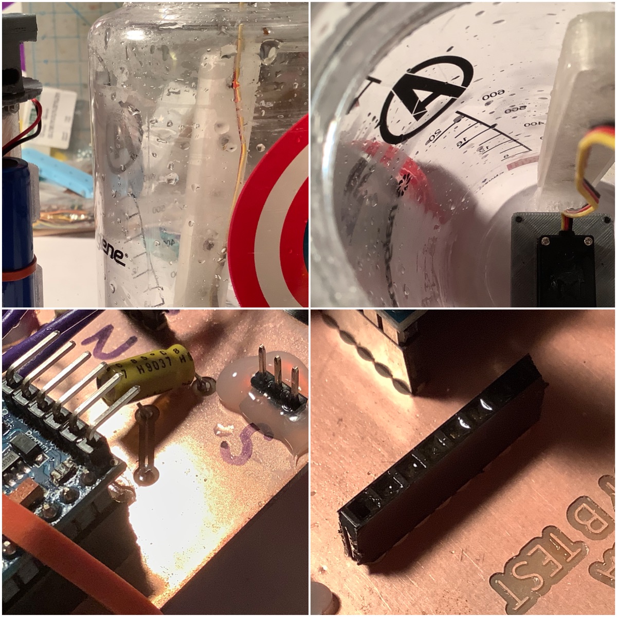
For the Eja Intelligent Buoy, there is an external wiper with magnets that slides across the polycarbonate enclosure, where internally there is a similar wiper with magnets, moving with a servo. The servo is a standard hobby servo. In the future with Leo’s Buoy B version, there’s also the capability to use a DC motor. The power source is a single 18650 Lipo.
In this test, the servo will be moving from 0 to 180 degrees and back. It completes one movement from 0-180 with a delay of 15 ms between each degree, so in total taking 2.7 seconds. It will then repeat this movement the other direction after 5 seconds. With the Arduino Servo library, 0 degrees corresponds to 1000 uS, and 180 degrees corresponds to 2000 uS for its pulse width.
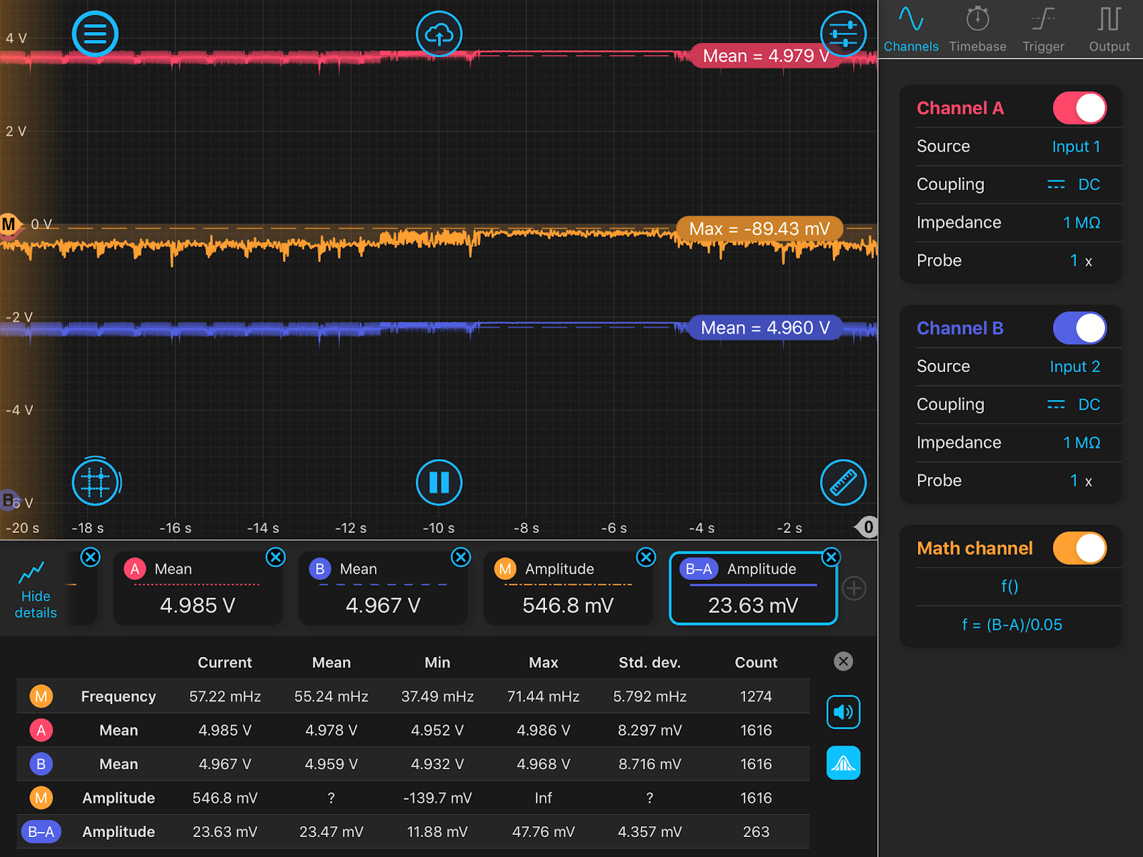
The Moku:Lab is set up on Oscilloscope mode with two probes connected on input. The other ends of the probes are connected to a makeshift board with a 0.05 ohm 5W resistor. This is a shunt resistor, where the two probes measure the voltage differential, and from there we can calculate the current using Ohm’s Law. Check out this guide for some useful tips about this. Here’s a Digikey search to find similar resistors.
Image source: Vivekanand - CircuitDigest
Using the Math function, we can see the result right away on the Moku:Lab. (Channel B - Channel A) / 0.05 Ohms will give us the current. Additionally, there are detail ‘widgets’ that can be added, along with rulers, to see more of the measurements.
To gather data for the graphs, a 2 minute datalog was recorded at 10 samples per second. (And 10 is the lowest possible setting, it can go much higher - Wow!)
Had the chance to record this testing session as a video too, check it out if you want to see the monitoring in action
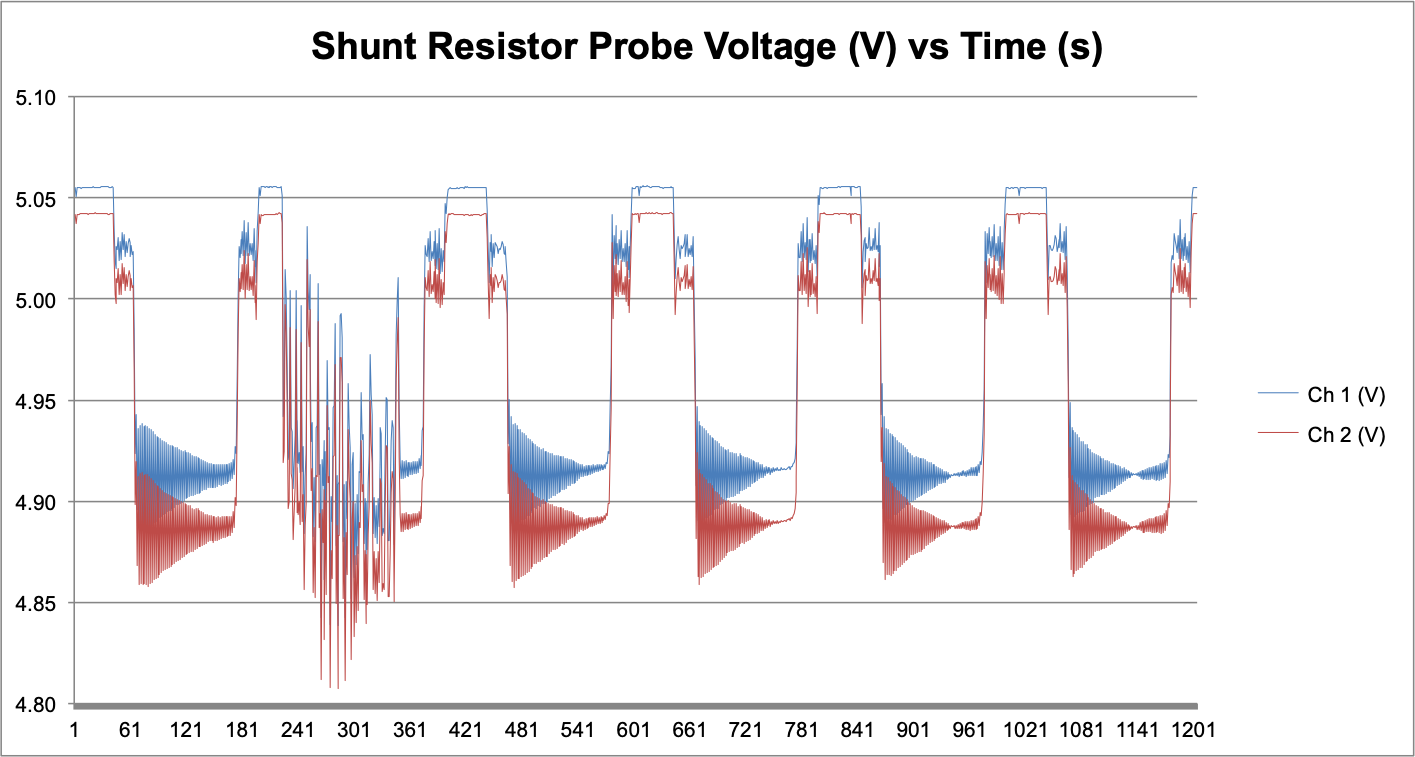
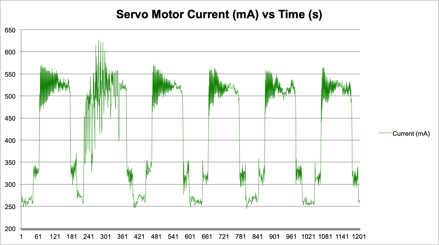
There are two graphs from this data. The first measuring the voltage from the probes attached to the shunt resistor. The second showing the current value in milliamps.There is a mistake with the timing. The program uploaded to the Arduino was set to a 16 MHz clock. However, the ATmega328 Arduino bootloader fuses are setup to be 8 MHz internal clock. My observation is that this changes how fast / slow millis() is passed, which is used for the waiting periods. The timing for the servo movement, approximately 2 seconds, is correct both in reality and on the graph. This error was figured out when doing post-analysis, and noticing that Serial Monitor was not giving the expected result at 9600 baud, and changing the clock speed worked.
During the idle periods, it seems the reason why the servo consumes so much current — (over 500 mA at times!) — is because it is forcing the gears towards their end limit. At this point, the servo is visibly shaking and is making an audible hum. It’s trying to achieve the destination, however it cannot reach it. The cause of this could be perhaps the pulsewidth in the servo library is not the pulsewidth limits for this servo. This makes sense, as each servo is different.
What did we learn from these measurements?
- Manually forcing the servo uses more current, and this makes sense as the servo is trying to maintain its set position
- Peak consumption by the servo when moving is around 350 mA
- When the servo is in delay is when it is using the least amount of current
- The boost regulator performs in excess of its limits (500mA) - sometimes even reaching supporting 600mA, without any brownouts
What to try next?
- Call servo.detach() when not using the servo, see what the current consumption is
- Adjusting the boundaries of the servo pwm so it is not “fighting” against itself
- Additional datalogs, and a datalog for battery usage while using different functionality
- Use the proper clock rate on the microcontroller (facepalm)
- Try the experiment again, but with using the wiper inside of the device
It was fun to collaborate with both Leo and Tobi when we were doing an initial set up of this experiment. Big thanks to Leo for answering a lot of questions I had about oscilloscopes and giving pointers on setting up the experiment. Looking forward to sharing learnings from the Moku:Lab with this project and beyond too!
-
Mech Update #18 - Test #04
09/27/2020 at 01:47 • 3 commentsNote: The content in this log was from Sept. 14
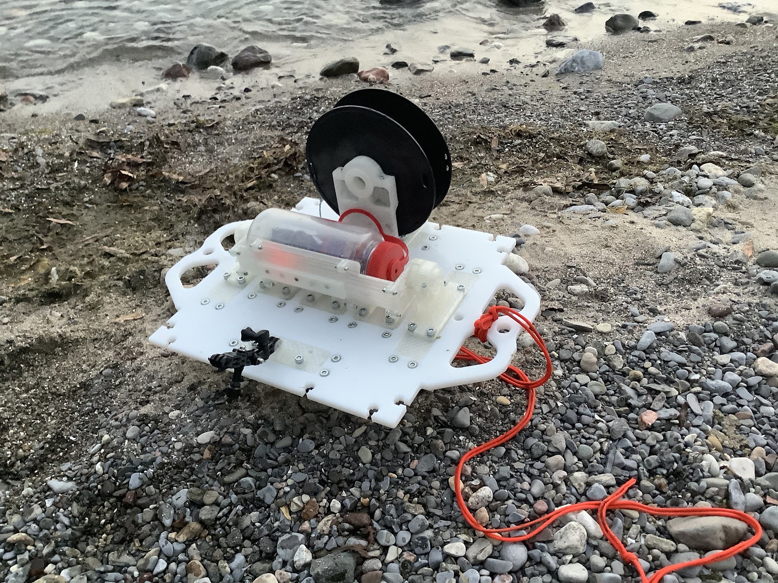
With all of the pieces printed now, it is time to assemble and test the final prototype release mechanism!
Objectives of the test
- Test the entire release mechanism in water
- Test the setup of the entire system
- Test the reliability / see what needs improving in the field
- Compare the results with the conditions from Test #01 (wave height ~2 cm) to Test #02 (wave height ~15 cm) to Test #03 (wave height ~20 - 30 cm) to Test #04 (wave height 0 cm)
The release mechanism concept worked! Check it out:
Here’s what the setup looked like:
Let’s begin from the start. The release mechanism and intelligent buoy are ready! Into the water it goes. It’s cool to notice in this gif how the water fills the infill of the 3D prints:
Here was the first try. The wipers don’t quite make contact with each other enough to move:
No problem, time to set it up again:
Sometimes the descent into the water can detach it:
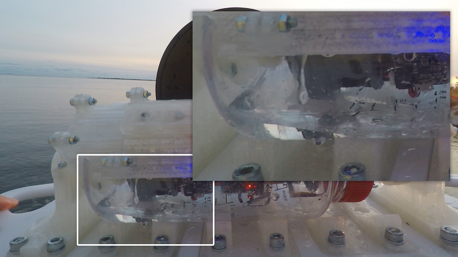
By the way, at this point it’s probably important to point out that there’s water in the buoy. …...THERE’S WATER (!!!) IN THE BUOY!
The next test worked flawlessly:
Slow motion:
Moved the release mechanism to a deeper location, and it works again!
At this point, the water in the buoy prevented the servo from working further. That concludes this test, and we verified that this works!
What changed
The previous test #03 verified that the external wiper can remain in place, even with some faster water current conditions. With this, it was time to proceed with the release mechanism idea.
The release mechanism is built on the top plate of the spool box design, milled out of HDPE. This piece was milled at the DesignLab and shipped here (along with some cut Nalgenes and more prints and gear! Thanks DesignLab!).
Inside of the buoy, the only piece that changed was the internal wiper - it was re-printed a bit stronger so that it replaced the hot-glued piece.
What worked
- The release mechanism worked multiple times! At different depths! Hooray!
What didn’t work
- Water in the enclosure
- Neopixels (wasn’t a priority to fix them for this test either)
- Internal wiper sometimes gets caught on the circuit board if it’s not attached to the external wiper magnets
- Load-in process can be a bit tedious to get the external magnets to pair with the internal (need stronger magnets)
- Sometimes on descent, the buoy can lose contact with the external wiper (need stronger magnets)
- No indication of when the servo was going to move - a blinking LED would have been helpful
Interestingly enough, the water did not ruin the electronics! After drying, everything still worked.
There were a few pieces that changed from the CAD model to the As-Built model.
- Leg pieces didn’t have a horizontal piece to rest on (this has since been changed in the design)
- Only 2 clamps for the weight - the height of the M6 screw head is too tall, so it pops over just enough to misplace the Nalgene bottle
- String attaches to center of spool, and the other end to a carabiner. Carabiner clips on to the circle in the Nalgene bottle head
- Axel for the spool is cut in half then glued together
What needs to change for future version
The most important thing: The servo needs to home itself to -90 degrees. This is because we don’t want the external wiper to fall ‘northward’, because it could snag on the rope that is attached to the buoy. By homing at -90, then having the servo move to +90, it would increase the likelihood of the external wiper falling ‘southward’ - because the servo would never be moving ‘northward’. The Nalgene is registered such that the lid is always ‘eastward’.
- Tape on the threads of the Nalgene enclosure
- Stronger magnets on internal and external wiper
- Weight distribution of the ballast on the release mechanism piece
- Create a sponge 'skirt' at the top of the Nalgene assembly. Add a conductivity / moisture sensor to this to monitor in case of water leakage. If the sensor is triggered, it could power off the whole system
- Indicator light for when servo will move
With the timing of this test and the conclusion of the official Hackaday Prize Dream Team program, this is likely the last test for now. Let’s see in the future how this will evolve and hopefully continue!
-
Future Improvements - PCB Design
09/19/2020 at 16:32 • 0 commentsThe following list presents some recommendations for future versions of the PCBs (Onboard Gateway V1.0, Buoy A V1.0 and Buoy B V1.0):
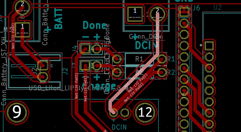
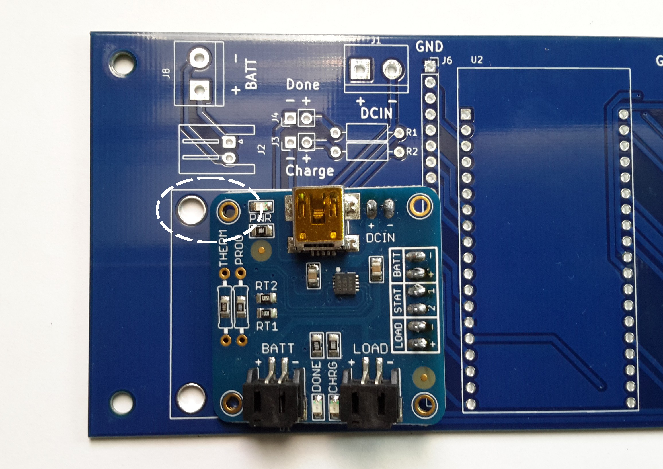
- Change the text that identifies the polarity of the terminal block DCin in the Onboard Gateway V1.0.
![]()
The problem is that the mount hole in the PCB identified (using white text) as "-" is connected con DCIN + in the USB LiIon/LiPoly charger. Also the mount hole identified as "+" is connected to the ground plane.
![]()
The "-" text should be changed to a "+". and the "+" text should be changed to a "-".
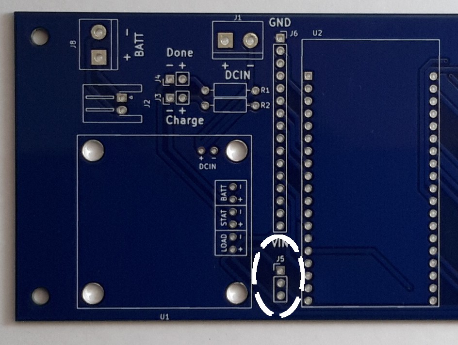
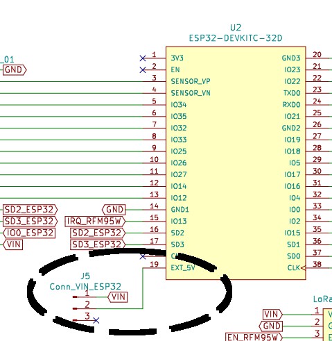
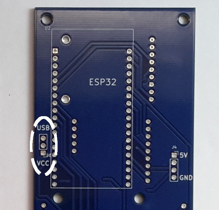
- Add text to identify VCC and USB in the J5 connector in the Onboard Gateway V1.0. This connector allows the user to select the power source for the ESP32 (VCC or USB).
![]()
The J5 connector has 3 positions:
- Connected to Vin
- Connected to the EXT_5V pin in the ESP32.
- Not connected.
![]()
The objective of J5 is to solder a CONN HEADER VERT 3POS 2.54MM in the PCB and then use a CONN JUMPER SHORTING .100" GOLD to define the power source of the ESP32. If the jumper connects 1 and 2 then the ESP32 is connected to Vin, if the jumper connects to 2 and 3 then the ESP32 es not connected to Vin, in that situation the ESP32 can be powered through USB. Text should be added to this connector to identify the jumper alternatives, like the following image (Buoy A V1.0).
![]()
- When the switch is turned off in the Onboard Gateway design, it is not possible to charge the battery. The battery can only be charged when the switch is on.
- Add a capacitor to the VCC line in all the PCBs (Onboard Gateway V1.0, Buoy A V1.0 and Buoy B V1.0).
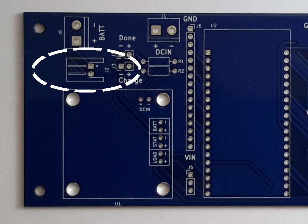
- Add a text describing the polarity for the JST-XH J2 connector in the Onboard Gateway V1.0.
![]()
J2 can only be connected in one way, but adding text to the PCB can be helpful during debugging.
- Add the switch to the PCB design of the 3 boards (Onboard Gateway V1.0, Buoy A V1.0 and Buoy B V1.0). The JST-XH connector directly connects the battery to the design, so it is not possible to turn off the boards if you use that connector.
- The pin IO0 is connected to the label IO5 in Buoy B V1.0 and IO5 is connected to the label IO0. The board requires those labels to be renamed in the schematic. Those pins are connected to the J7 Conn_Extras connector that can be used to add more modules to the design.
![]()
- Augment the diameter of the mount holes in the PCB, difference in the precision and tolerance of the machines used to manufacture the PCBs can make the mount holes slightly smaller. In the current design, if the mount holes are slightly smaller, the header will not fit in the PCB.
- Adjust the size of the screw holes for the USB LiIon/LiPoly charger in the Onboard Gateway V1.0.
![]()
- Add internal leds for the PCBs. The Onboard Gateway V1.0 has connectors for external leds (male headers), but the design can also benefit from having internal ones (directly soldered). Buoy A V1.0 and Buoy B V1.0 have connector with the extra pins available in the ESP32-DEVKITC-32D, so it is possible to connect leds to the design, but those boards can also benefit from having internal leds (directly soldered).
-
Buoy A V.10 - Bill of Materials
09/19/2020 at 14:31 • 0 commentsThis log presents a price of each one of the elements related to the electronics of the Buoy A V1.0. The following table presents the price per unit and the price per 1000 units for each component, taking into consideration the changes in the price per unit when bought in groups of 1000 units.
PCB Components
Name Price per unit Price per 1000 units PCB $0.50 $767.00 ESP32-DEVKITC-32D $10.00 $10,000.00 TB6612FNG MOTOR DRIVER BOARD $5.45 $5,450.00 CONN HDR 5POS 0.1 GOLD PCB $0.47 $243.54 CONN HEADER VERT 40POS 2.54MM $2.29 $1,272.00 CONN HDR 6POS 0.1 TIN PCB $0.52 $265.82 CONN HDR 8POS 0.1 TIN PCB $0.65 $334.13 CONN HDR 8POS 0.1 TIN PCB $0.65 $334.13 CONN HDR 8POS 0.1 TIN PCB $0.65 $334.13 CONN HDR 19POS 0.1 TIN PCB $1.17 $643.68 CONN HDR 19POS 0.1 TIN PCB $1.17 $643.68 CONN HEADER R/A 3POS 2.5MM $0.22 $100.49 TERM BLK 3P SIDE ENT 5.08MM PCB $0.85 $289.00 TERM BLK 2P SIDE ENT 5.08MM PCB $0.80 $205.20 CONN HDR 9POS 0.1 GOLD PCB $0.67 $368.64 CONN HDR 9POS 0.1 GOLD PCB $0.67 $368.64 CONN HDR 4POS 0.1 GOLD PCB $0.47 $240.57 CONN HDR 9POS 0.1 GOLD PCB $0.67 $368.64 CONN HDR 10POS 0.1 TIN PCB $0.65 $360.00 Adafruit Ultimate GPS $39.95 $39,950.00 RFM95W LoRa Radio $19.95 $19,950.00 SIM7600CE-T 4G(LTE) Arduino Shield $69.00 $69,000.00 External Components
Name Price per unit Price per 1000 units SERVOMOTOR RC 5V HIGH TORQUE $9.95 $9,950.00 CR2032 Lithium Coin Cell Battery $0.95 $860.00 DP OFF-ON TABS M12X0.75 DC $3.40 $2,270.00 20W ADJUSTABLE DC-DC BUCK CONVERTER $4.95 $4,950.00 2200mAh 7.4V 2S 50C LiPo $24.99 $24,990.00
Overall PricePrice per unit Price per 1000 units $201.01 $194,175.16 -
Buoy B V.10 - Bill of Materials
09/18/2020 at 18:58 • 0 commentsThis log presents a price of each one of the elements related to the electronics of the Buoy B V1.0. The following table presents the price per unit and the price per 1000 units for each component, taking into consideration the changes in the price per unit when bought in groups of 1000 units.
PCB Components
Name Price per unit Price per 1000 units PCB $0.50 $767.00 ESP32-DEVKITC-32D $10.00 $10,000.00 TB6612FNG MOTOR DRIVER BOARD $5.45 $5,450.00 CONN HDR 19POS 0.1 TIN PCB $1.17 $643.68 CONN HDR 9POS 0.1 GOLD PCB $0.67 $368.64 CONN HDR 9POS 0.1 GOLD PCB $0.67 $368.64 CONN HDR 8POS 0.1 TIN PCB $0.65 $334.13 CONN HDR 8POS 0.1 TIN PCB $0.65 $334.13 CONN HDR 19POS 0.1 TIN PCB $1.17 $643.68 TERM BLK 2P SIDE ENT 5.08MM PCB $0.80 $205.20 TERM BLK 2P SIDE ENT 5.08MM PCB $0.80 $205.20 TERM BLK 3P SIDE ENT 5.08MM PCB $0.85 $289.00 CONN HDR 6POS 0.1 TIN PCB $0.52 $265.82 CONN HDR 5POS 0.1 GOLD PCB $0.47 $243.54 CONN HEADER VERT 40POS 2.54MM $2.29 $1,272.00 CONN HEADER R/A 3POS 2.5MM $0.22 $100.49 Adafruit Ultimate GPS $39.95 $39,950.00 RFM95W LoRa Radio $19.95 $19,950.00 External Components
Name Price per unit Price per 1000 units SERVOMOTOR RC 5V HIGH TORQUE $9.95 $9,950.00 CR2032 Lithium Coin Cell Battery $0.95 $860.00 DP OFF-ON TABS M12X0.75 DC $3.40 $2,270.00 20W ADJUSTABLE DC-DC BUCK CONVERTER $4.95 $4,950.00 2200mAh 7.4V 2S 50C LiPo $24.99 $24,990.00 Overall Price
Price per unit Price per 1000 units $131.02 $124,411.15 -
Mechanical Design Specifications
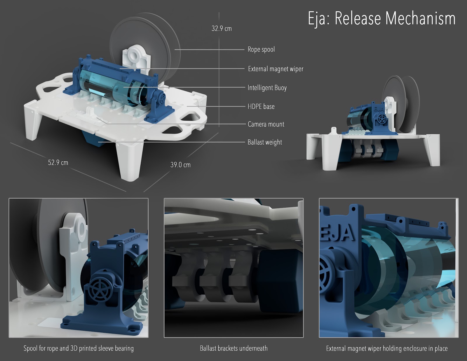
09/18/2020 at 18:54 • 0 commentsThe Eja ropeless gear system consists of three parts: Release Mechanism, Intelligent Buoy, and Onboard Gateway. Here are the mechanical design specifications for each, also available as a pdf here.
Release Mechanism
3D viewer: https://a360.co/3msDSha
Files: https://github.com/RobotGrrl/Hackaday-CXL/tree/master/Design/release_mechanism
Length
52.9 cm
Width
39.0 cm
Height
32.9 cm
Approximate Weight
15 lbs / 6.8 kg (including ballast)
Materials
0.375 in HDPE base, PLA 3D printed pieces
Max Depth
TBD
Eja Bill of Materials - Release Mechanism
Last Updated: Sept. 18, 2020
All fasteners for prototype are zinc-plated steel
Item
Qty
Cost (USD)
McMaster Part #
Source
Notes
M6 x 16 mm
32
3.32
90128A263
M6 x 25 mm
30
3.97
90128A265
M6 Washer
50
2.15
98688A116
M6 Hex Nut
62
1.61
90591A151
M3 x 10 mm
12
1.70
95263A134
M3 x 16 mm
12
2.11
95263A158
M3 Washer
28
0.96
98688A112
M3 Hex Nut
24
0.56
90591A250
Magnets N52 (large)
5
4.85
5862K116
TOTAL MECH COMPONENTS
21.22
0.375 in Natural HDPE 24 x 48 in
0.5
42.50
Cost / in^2 = 0.04
1 kg 3D Printer Filament PLA
2
57.98
Misc. rope, cord, carabiner
1
5.00
Random
10 lbs Dumbbell
1
7.00
Canadian Tire
Spool holder
1
1.00
TOTAL MATERIALS
113.48
CNC machine time
20
20
DesignLab
1 / min
3D printer time
1200
60
EK's 3D printer
0.05 / min
Injection moulding time
0
0
Assembly time
90
22.5
EK
15 / h
TOTAL MACHINE TIME
102.5
GRAND TOTAL
237.20
Parametric Design
Here are the values used for parametric design
![]()
Intelligent Buoy
3D viewer: https://a360.co/3hJjc0R
Github: https://github.com/RobotGrrl/Hackaday-CXL/tree/master/Design/intelligent_buoy
Diameter
9.3 cm
Height
20.8 cm
Approximate Weight
500 g
Materials
Polycarbonate (‘Tritan’), PLA 3D printed pieces, Neodynium magnets, FR4 circuit board for structural strength
Waterproof Rating
Waterproof*
*Further testing is needed to determine depth
Eja Bill of Materials - Intelligent Buoy B
Last Updated: Sept. 18, 2020
All fasteners for prototype are zinc-plated steel
Item
Qty
Cost (USD)
McMaster Part #
Source
Notes
M2.5 x 8 mm
4
0.54
90128A184
M2.5 x 6 mm
14
1.85
90128A183
M2.5 Washer
4
0.13
98688A111
M2.5 Hex Nut
8
0.18
90591A270
M3 x 10 mm
4
0.57
95263A134
M3 Washer
0
0.00
98688A112
M3 Hex Nut
4
0.09
90591A250
Magnets N52 (small)
4
3.04
5862K103
Magnets N52 (large)
5
4.85
5862K116
TOTAL MECH COMPONENTS
11.24
Nalgene 1L wide mouth enclosure
1
20.00
SportChek
1 kg 3D Printer Filament PLA
0.25
7.25
Misc. glue, wires
1
1.50
Random
TOTAL MATERIALS
28.75
3D printer time
60
3
EK's 3D printer
0.05 / min
Injection moulding time
0
0
Assembly time
20
5
EK
15 / h
TOTAL MACHINE TIME
8
GRAND TOTAL
47.99
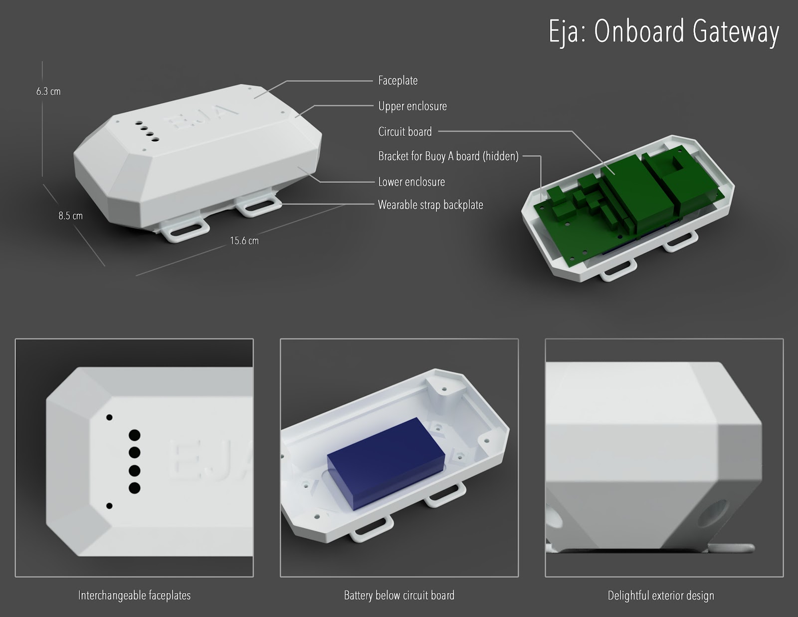
Onboard Gateway
3D viewer: https://a360.co/32DGUHE
Files: https://github.com/RobotGrrl/Hackaday-CXL/tree/master/Design/onboard_gateway
Length
15.6 cm
Width
8.5 cm
Height
6.3 cm
Approximate Weight
300 g
Materials
PLA 3D printed pieces
Waterproof Rating
Not waterproof
Eja Bill of Materials - Onboard Gateway
Last Updated: Sept. 18, 2020
All fasteners for prototype are zinc-plated steel
Item
Qty
Cost (USD)
McMaster Part #
Source
Notes
M2.5 x 8 mm
8
1.07
90128A184
M2.5 x 6 mm
0
0.00
90128A183
M2.5 Washer
0
0.00
98688A111
M2.5 Hex Nut
8
0.18
90591A270
M3 x 10 mm
4
0.57
95263A134
M3 Washer
0
0.00
98688A112
M3 Hex Nut
4
0.09
90591A250
TOTAL MECH COMPONENTS
1.91
1 kg 3D Printer Filament PLA
0.75
21.74
TOTAL MATERIALS
21.74
3D printer time
180
9
EK's 3D printer
0.05 / min
Injection moulding time
0
0
Assembly time
10
2.5
EK
15 / h
TOTAL MACHINE TIME
11.5
GRAND TOTAL
35.15
-
Onboard Gateway V.10 - Bill of Materials
09/18/2020 at 18:30 • 0 commentsThis log presents a price of each one of the elements related to the electronics of the Onboard Gateway V1.0. The following table presents the price per unit and the price per 1000 units for each component, taking into consideration the changes in the price per unit when bought in groups of 1000 units.
PCB Components
Name Price per unit Price per 1000 units PCB $0.50 $767.00 TERM BLK 2P SIDE ENT 5.08MM PCB $0.80 $205.20 CONN HEADER R/A 2POS 2.5MM $0.18 $80.68 CONN HEADER VERT 40POS 2.54MM $2.29 $1,272.00 CONN HDR 6POS 0.1 TIN PCB $0.52 $265.82 USB LiIon/LiPoly charger $12.50 $10,000.00 RES 249 OHM 1/4W 1% AXIAL $0.10 $11.00 RES 249 OHM 1/4W 1% AXIAL $0.10 $11.00 TERM BLK 2P SIDE ENT 5.08MM PCB $0.80 $205.20 CONN HDR 2POS 0.1 GOLD PCB $0.33 $157.50 CONN JUMPER SHORTING .100" GOLD $0.10 $26.46 CONN HDR 19POS 0.1 TIN PCB $1.17 $643.68 ESP32-DEVKITC-32D $10.00 $10,000.00 CONN HDR 19POS 0.1 TIN PCB $1.17 $643.68 CONN HDR 16POS 0.1 TIN PCB $0.98 $541.44 CONN HDR 12POS 0.1 TIN PCB $0.78 $432.00 CONN HDR 9POS 0.1 GOLD PCB $0.67 $368.64 RES 100 OHM 3W 5% AXIAL $0.71 $264.44 RES 100 OHM 3W 5% AXIAL $0.71 $264.44 RES 100 OHM 3W 5% AXIAL $0.71 $264.44 RES 100 OHM 3W 5% AXIAL $0.71 $264.44 CONN HDR 5POS 0.1 GOLD PCB $0.47 $243.54 RFM95W LoRa Radio $19.95 $19,950.00 External Components
Name Price per unit Price per 1000 units Lithium Ion Battery - 3.7v 2000mAh $12.50 $11,250.00 Micro USB Board $2.50 $2,500.00 LED ASSORTED RESISTOR 5MM 20PK $9.69 $9,690.00 DP OFF-ON TABS M12X0.75 DC $3.40 $2,270.00 Overall Price
Price per unit Price per 1000 units $84.34 $72,592.60 -
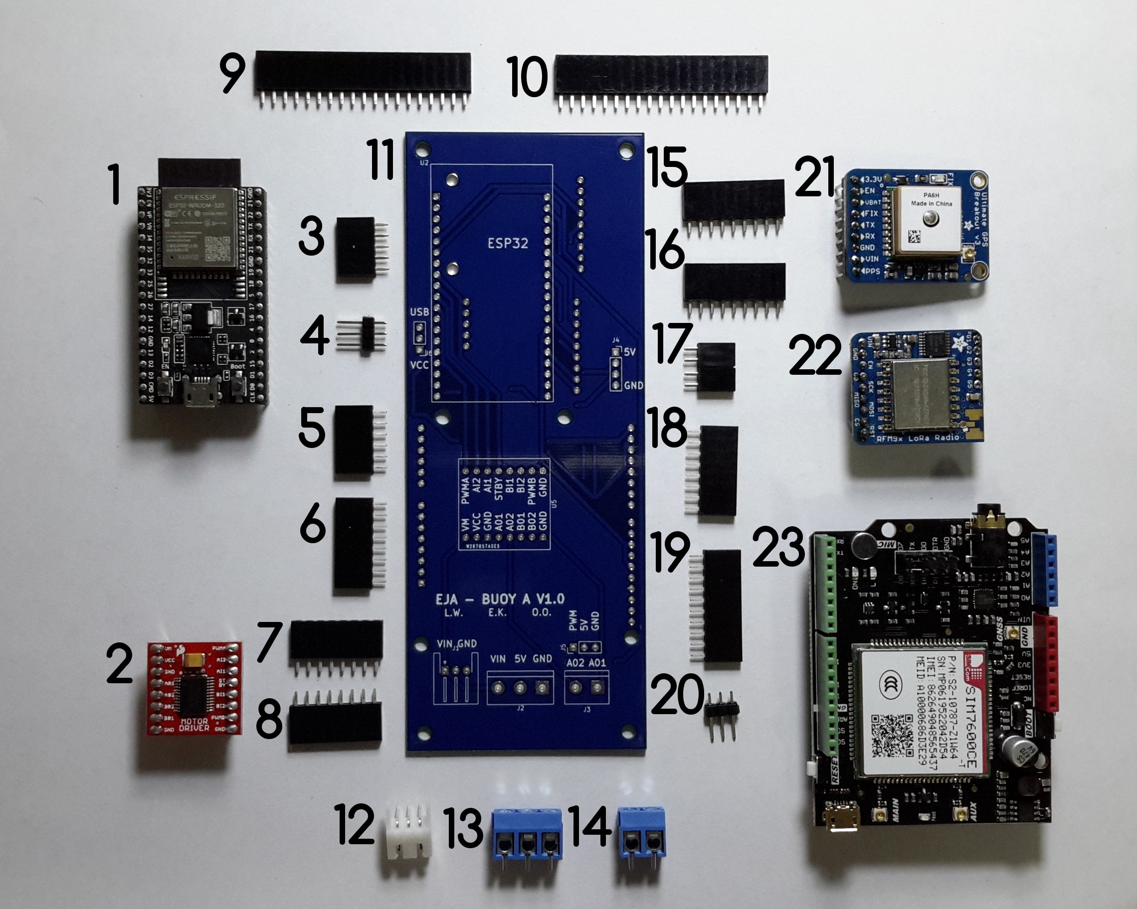
Buoy A V1.0 - Assembly
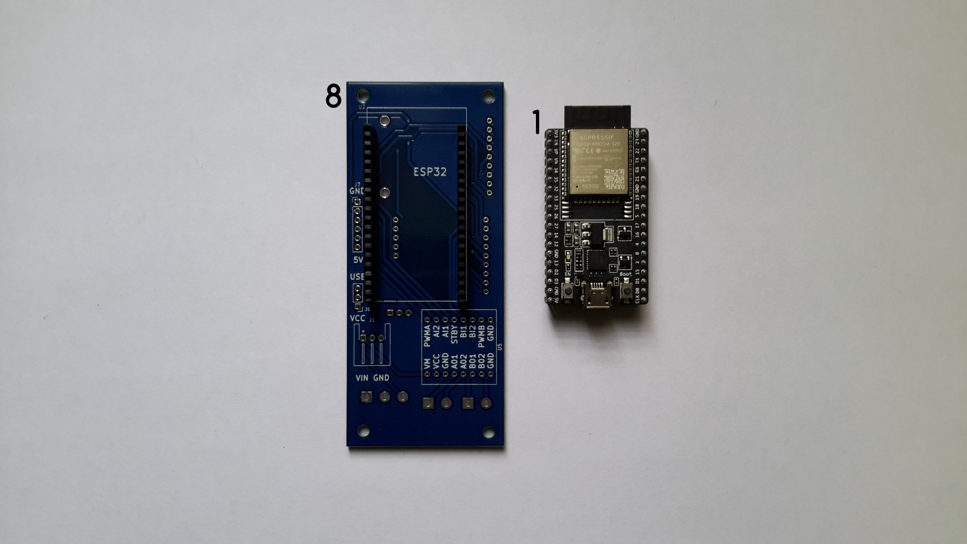
09/18/2020 at 04:37 • 0 commentsThis log describes the recommended assembly instructions for the Buoy A V1.0 PCB. The following image shows all the required components, with an identification number that will be used in the log.
![]()
Components List:
- ESP32-DEVKITC-32D
- TB6612FNG MOTOR DRIVER BOARD
- CONN HDR 5POS 0.1 GOLD PCB
- CONN HEADER VERT 3POS 2.54MM
- CONN HDR 6POS 0.1 TIN PCB
- CONN HDR 8POS 0.1 TIN PCB
- CONN HDR 8POS 0.1 TIN PCB
- CONN HDR 8POS 0.1 TIN PCB
- CONN HDR 19POS 0.1 TIN PCB
- CONN HDR 19POS 0.1 TIN PCB
- Buoy A V1.0
- CONN HEADER R/A 3POS 2.5MM
- TERM BLK 3P SIDE ENT 5.08MM PCB
- TERM BLK 2P SIDE ENT 5.08MM PCB
- CONN HDR 9POS 0.1 GOLD PCB
- CONN HDR 9POS 0.1 GOLD PCB
- 2 CONN HDR 2POS 0.1 GOLD PCB
- CONN HDR 9POS 0.1 GOLD PCB
- CONN HDR 10POS 0.1 TIN PCB
- CONN HEADER VERT 3POS 2.54MM
- Adafruit Ultimate GPS
- RFM95W LoRa Radio
- SIM7600CE-T 4G(LTE) Arduino Shield
It is possible to solder the components in many different orders, I'll describe the one that I followed, it can used as a reference.
Instructions
a.Solder the female headers 9 and 10 used to connect the ESP32-DEVKITC-32D to Buoy A V1.0.
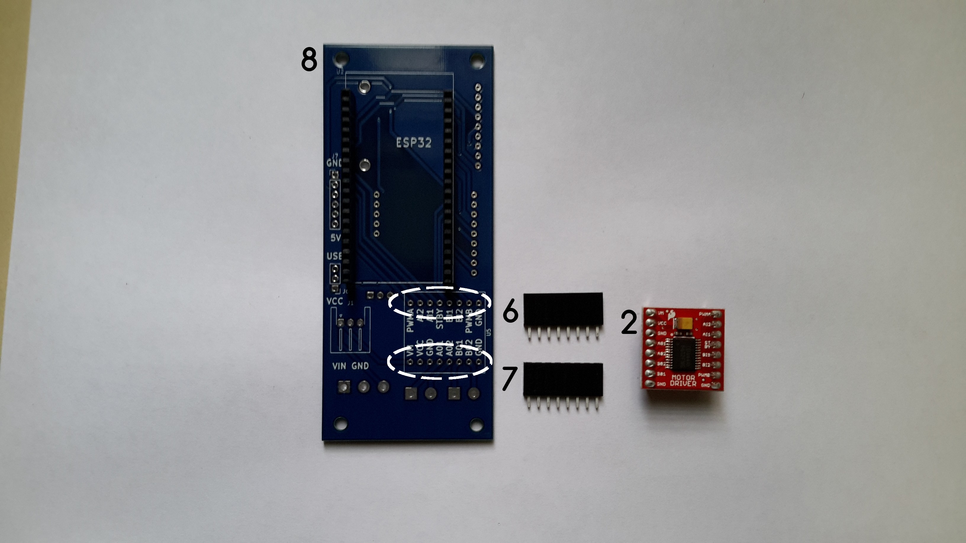
b.Solder the female headers 7 and 8 used to connect the TB6612FNG MOTOR DRIVER BOARD to Buoy A V1.0.
c. Solder the female header 17 to Buoy B V1.0.
d. Solder the 3POS Horizontal JST-XH connector (12).
e. Solder the male header 4.
f. Solder the female headers 3 and 16 used to connect the RFM95W LoRa Radio to Buoy A V1.0.
g. Solder the female headers 15, used to connect the Adafruit Ultimate GPS to Buoy A V1.0.
i. Solder the male connector 20 to Buoy A V1.0.
j.Solder the female headers 5, 6, 18 and 19 used to connect the SIM7600CE-T 4G(LTE) Arduino Shield to Buoy A V1.0.
k. Solder the terminal blocks 13 and 14 to Buoy A V1.0.
-
Buoy B V1.0 - Assembly
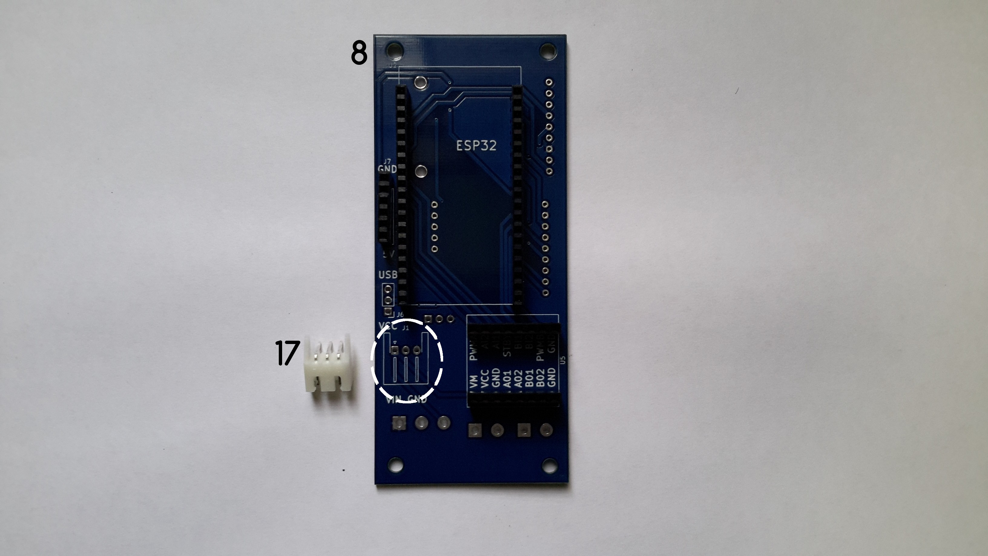
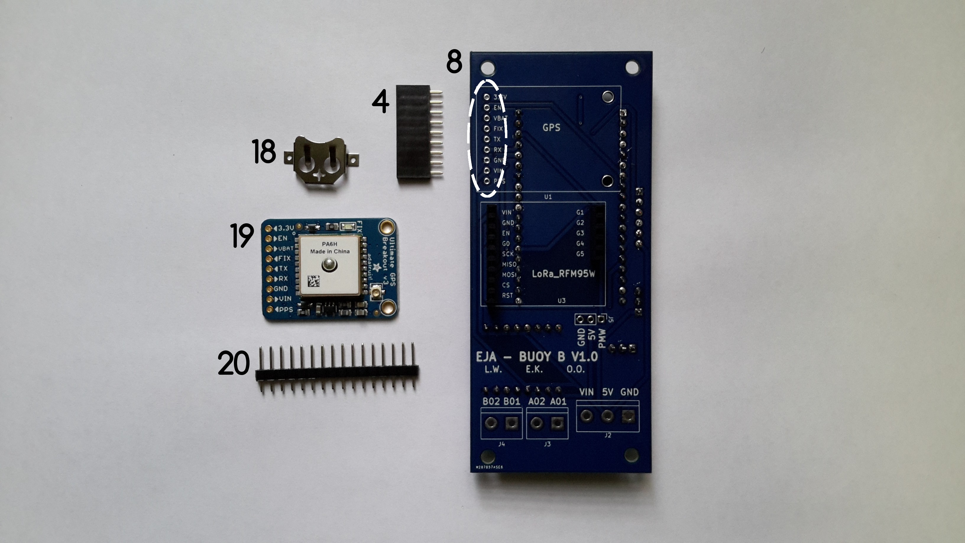
09/16/2020 at 01:56 • 0 commentsThis log describes the recommended assembly instructions for the Buoy B V1.0 PCB. The following image shows all the required components, with an identification number that will be used in the log.
![]()
Components List:
- ESP32-DEVKITC-32D
- TB6612FNG MOTOR DRIVER BOARD
- CONN HDR 19POS 0.1 TIN PCB
- CONN HDR 9POS 0.1 GOLD PCB
- CONN HDR 9POS 0.1 GOLD PCB
- CONN HDR 8POS 0.1 TIN PCB
- CONN HDR 8POS 0.1 TIN PCB
- Buoy B V1.0
- CONN HDR 19POS 0.1 TIN PCB
- TERM BLK 2P SIDE ENT 5.08MM PCB
- TERM BLK 2P SIDE ENT 5.08MM PCB
- TERM BLK 3P SIDE ENT 5.08MM PCB
- CONN HDR 6POS 0.1 TIN PCB
- CONN HDR 5POS 0.1 GOLD PCB
- CONN HEADER VERT 3POS 2.54MM
- CONN HEADER VERT 3POS 2.54MM
- CONN HEADER R/A 3POS 2.5MM
- Coin cell holder (included in Adafruit Ultimate GPS)
- Adafruit Ultimate GPS
- CONN HDR 16POS 0.1 TIN PCB (included in Adafruit Ultimate GPS)
- RFM95W LoRa Radio
- CONN HEADER VERT 16POS 2.54MM (included in RFM95W LoRa Radio)
It is possible to solder the components in many different orders, I'll describe the one that I followed, it can used as a reference.
Instructions
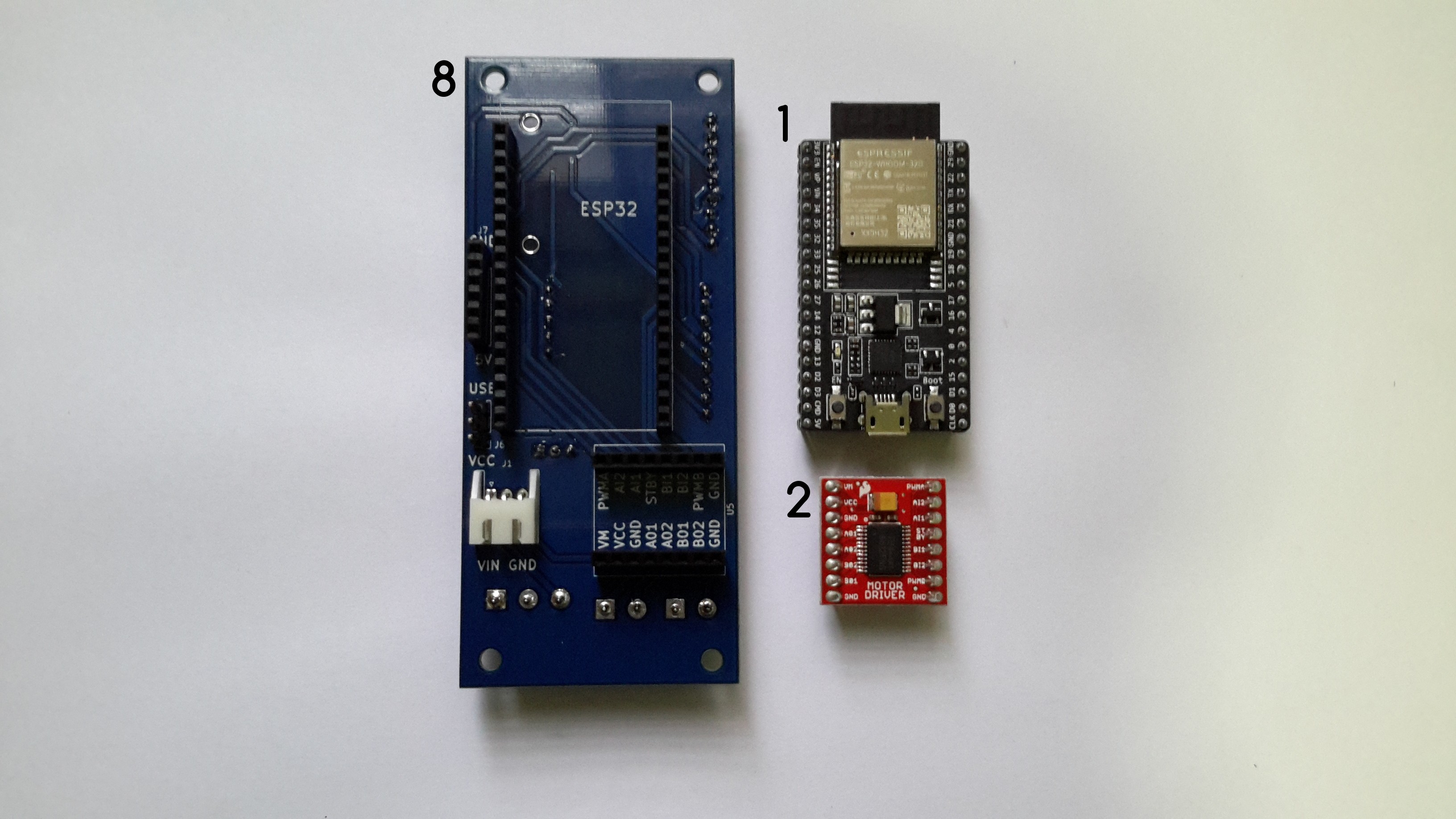
a.Solder the female headers 3 and 9 used to connect the ESP32-DEVKITC-32D to Buoy B V1.0.
![]()
Once the female headers are soldered, the ESP32-DEVKITC-32D connects to Buoy B V1.0 through the headers.
![]()
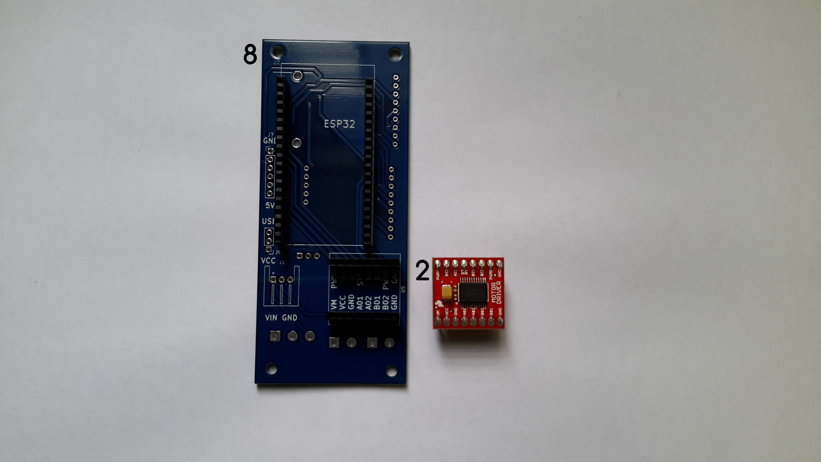
b.Solder the female headers 6 and 7 used to connect the TB6612FNG MOTOR DRIVER BOARD to Buoy B V1.0.
![]()
The TB6612FNG MOTOR DRIVER connects to Buoy B V1.0 using the headers.
![]()
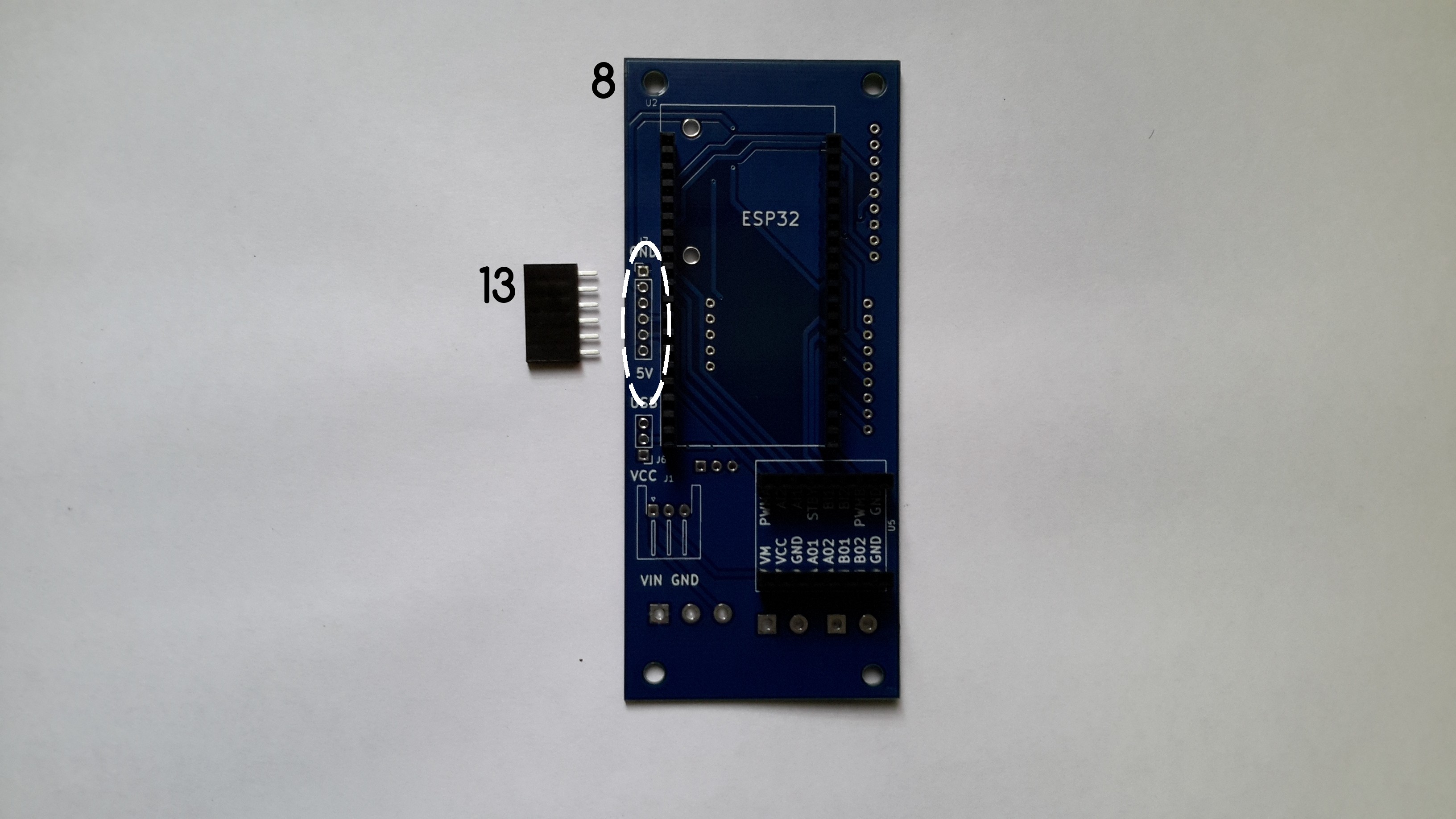
c. Solder the female header 13 to Buoy B V1.0.
![]()
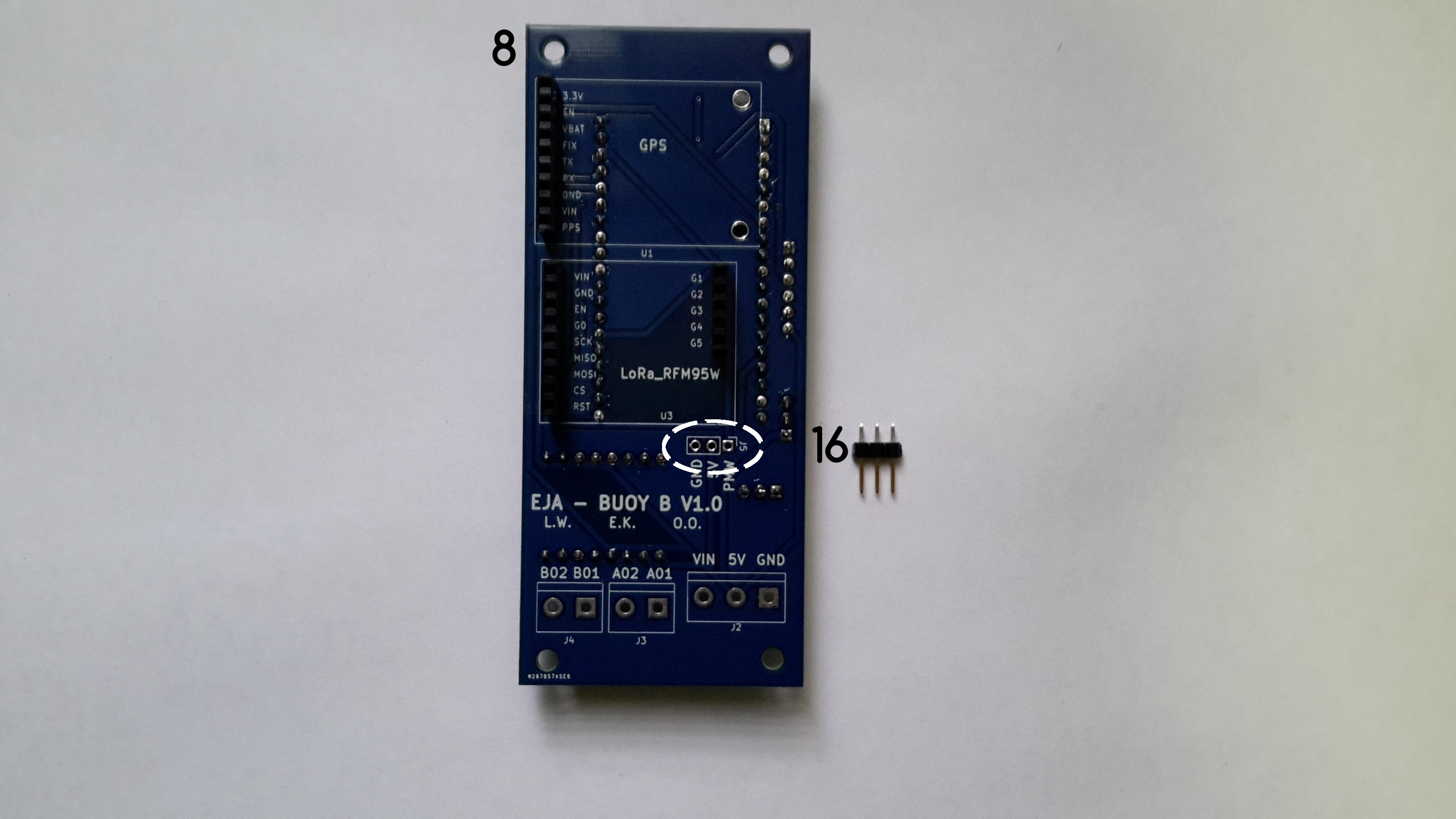
d. Solder the 3POS Horizontal JST-XH connector (17).
![]()
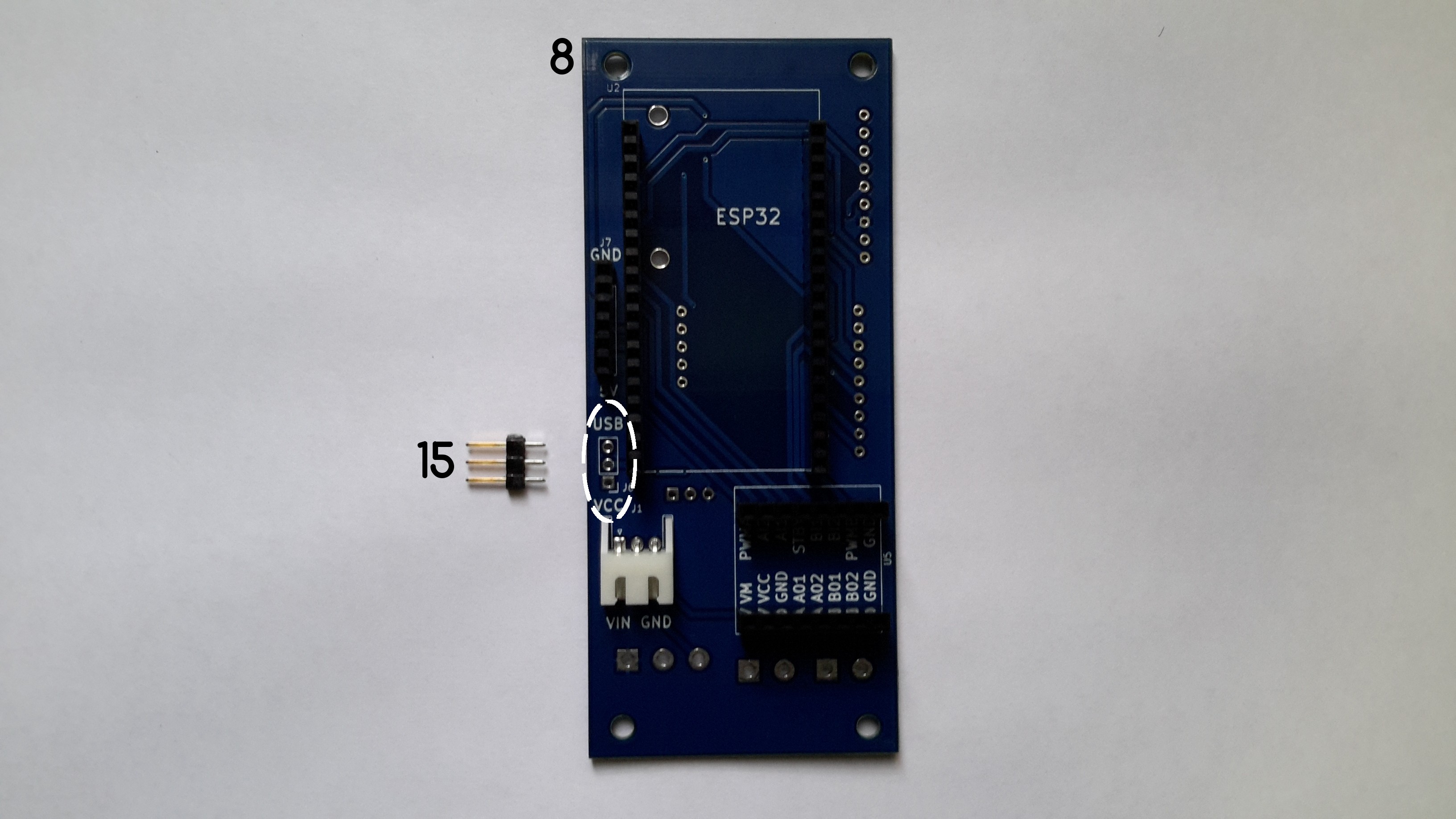
e. Solder the male header 15.
![]()
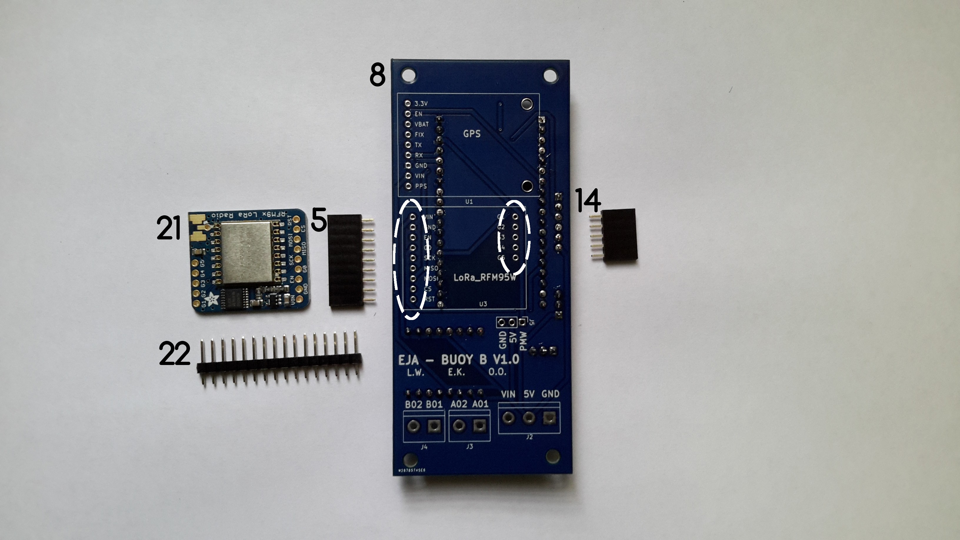
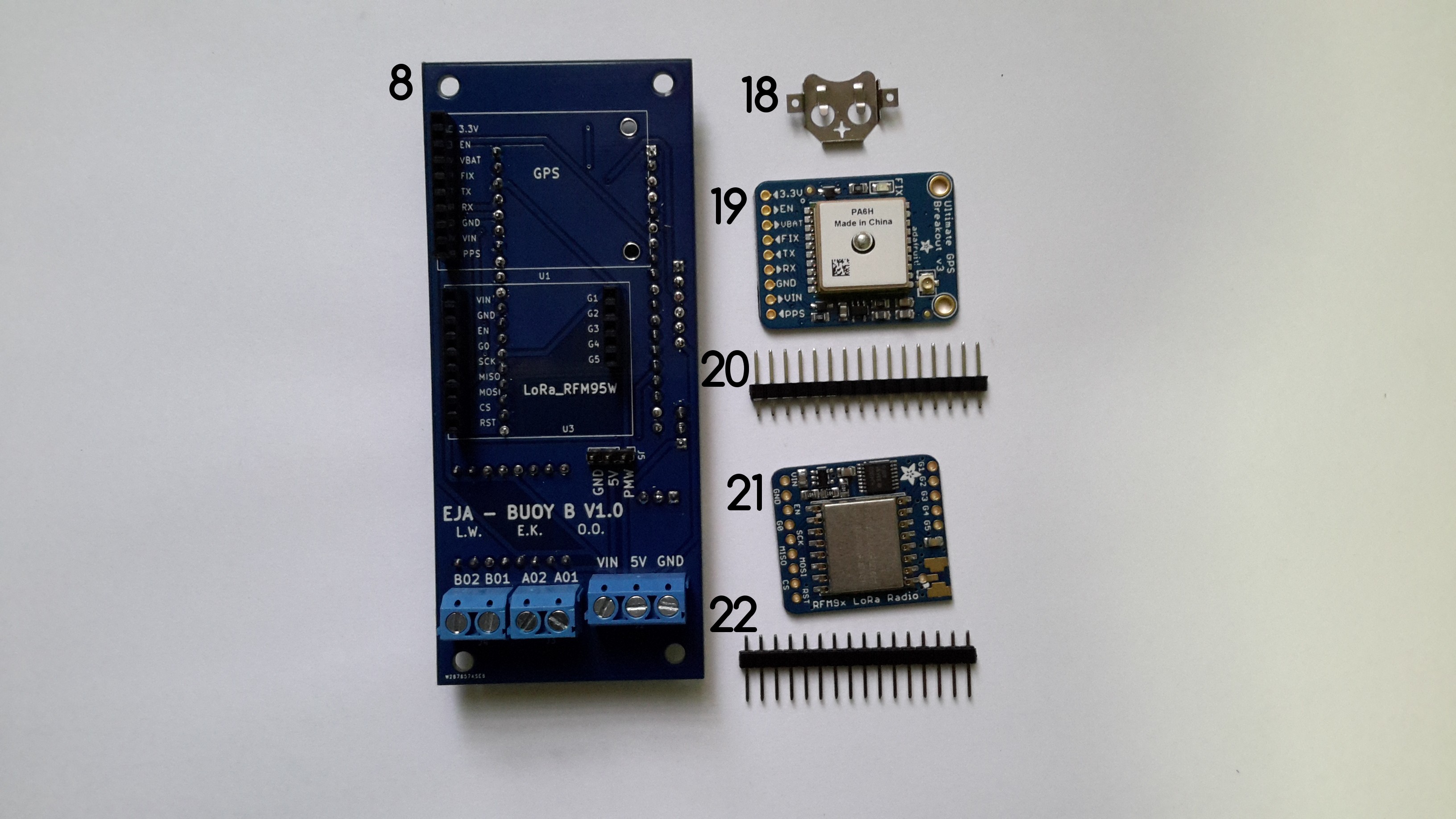
f. Solder the female headers 5 and 14 used to connect the RFM95W LoRa Radio to Buoy B V1.0.
![]()
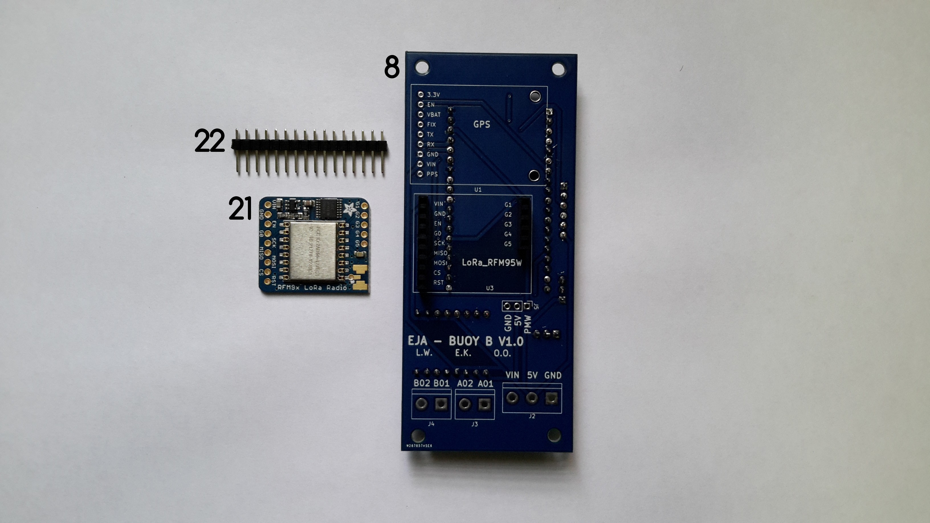
g. Solder the male headers 22 to the RFM95W LoRa Radio. To do that it is necessary to cut a CONN HEADER VERT 9POS 2.54MM and a CONN HEADER VERT 5POS 2.54MM from the component 22. The RFM95W LoRa Radio connects to Buoy B V1.0 through the headers.
![]()
h. Solder the female headers 4, used to connect the Adafruit Ultimate GPS to Buoy B V1.0. Solder the male headers 20 to the Adafruit Ultimate GPS. To do that it is necessary to cut a CONN HEADER VERT 9POS 2.54MM the component 20. The Adafruit Ultimate GPS connects to Buoy B V1.0 through the headers.
![]()
i. Solder the male connector 16 to Buoy B V1.0.
![]()
j. Solder the terminal blocks 10, 11 and 12 to Buoy B V1.0.
Front Layer and Back Layer
The modules connected to the front layer of Buoy B V1.0 are the ESP32-DEVKITC-32D and the TB6612FNG MOTOR DRIVER BOARD.
![]()
The modules connected to the back layer of Buoy B V1.0 are the Adafruit Ultimate GPS and the RFM95W LoRa Radio.
![]()
-
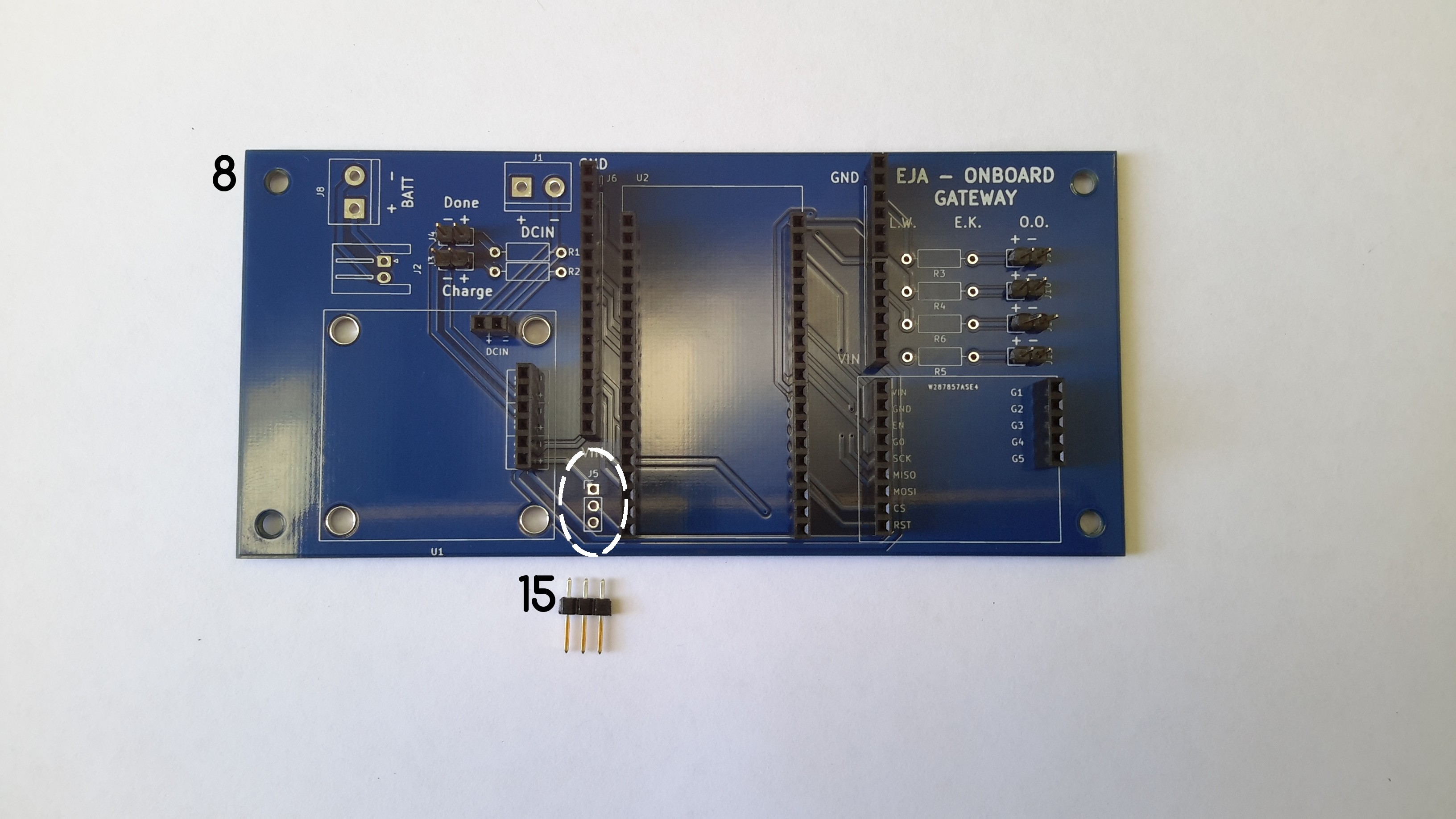
Onboard Gateway V1.0 - Assembly
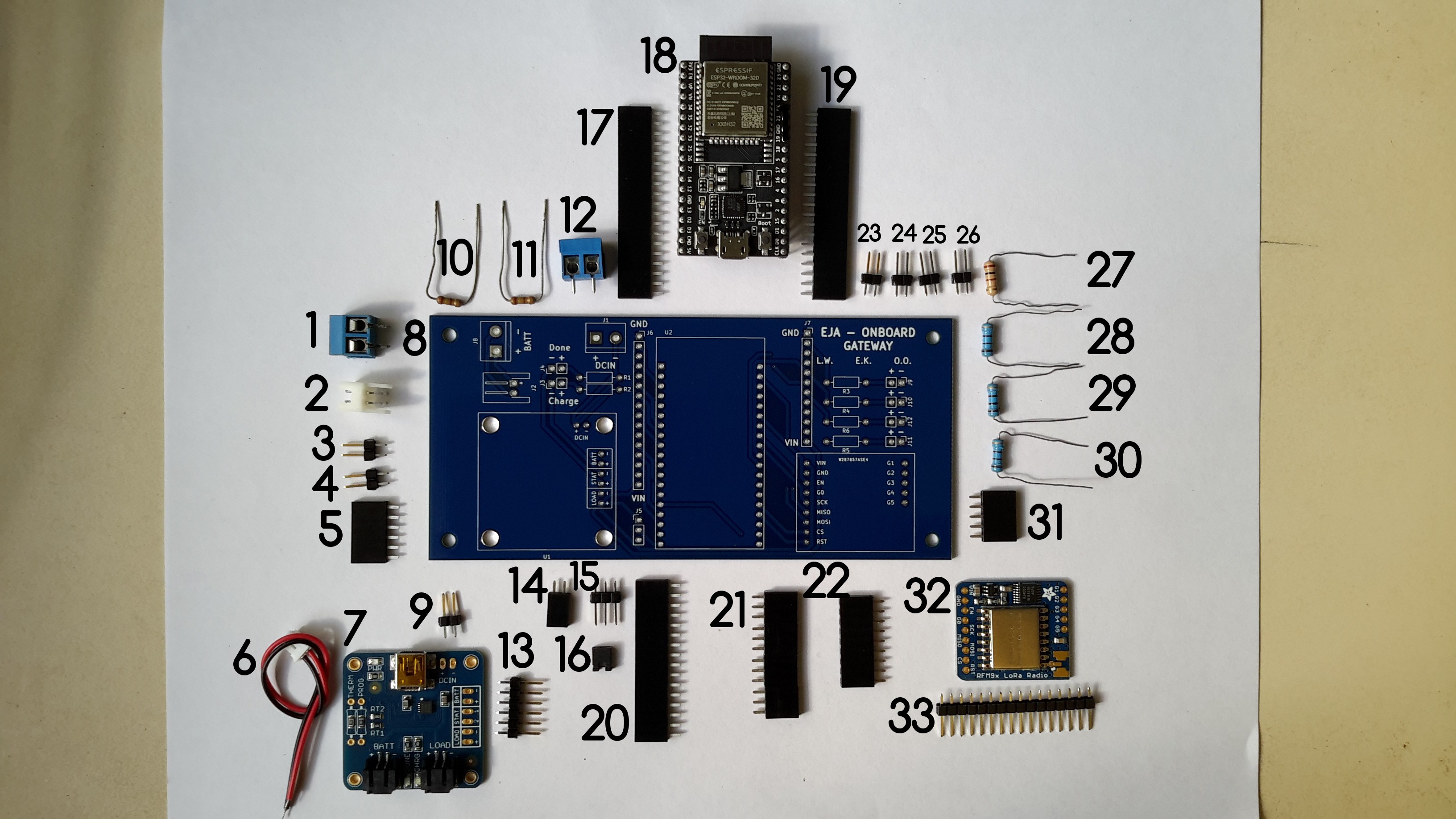
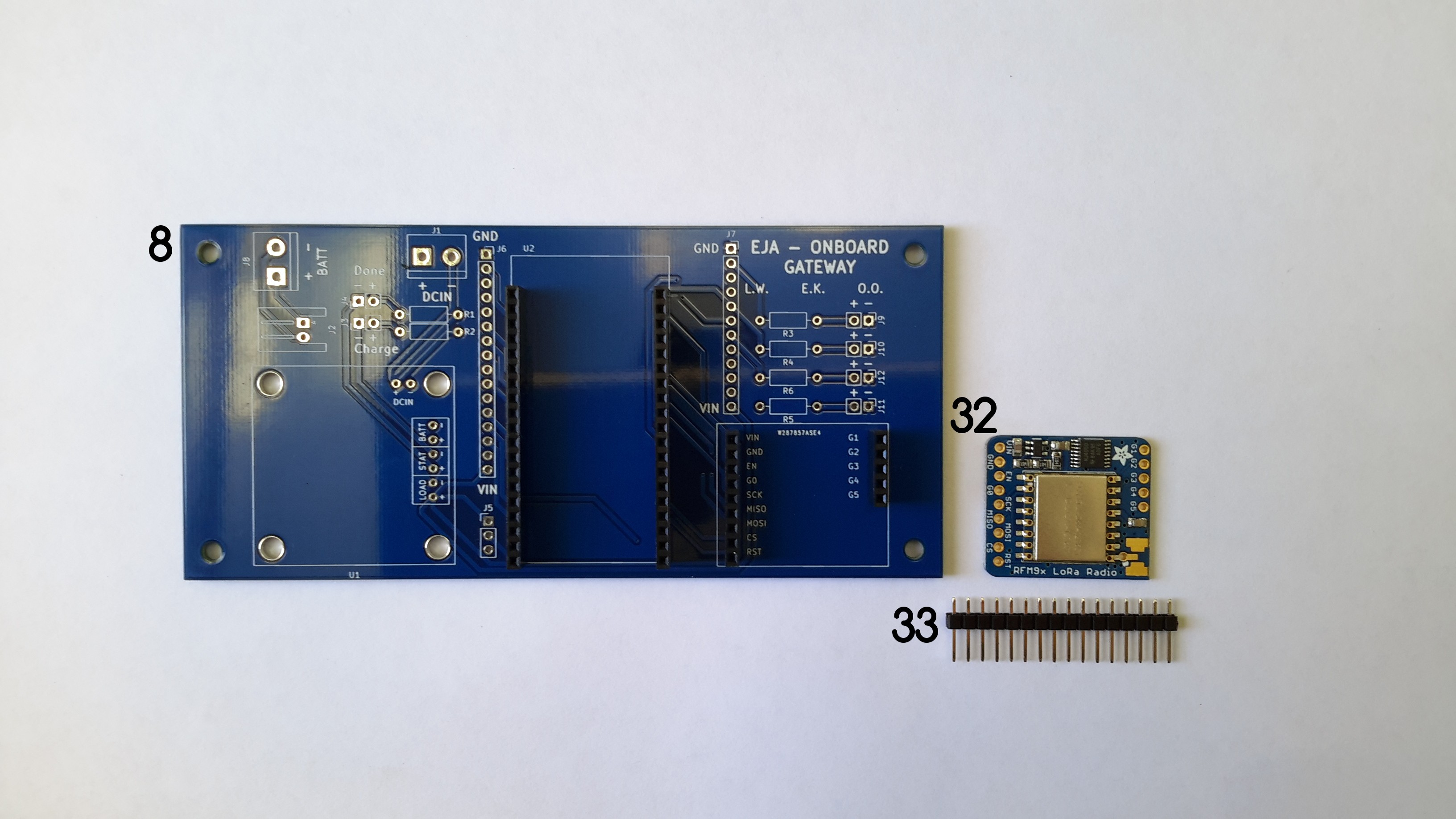
09/16/2020 at 01:22 • 0 commentsThis log describes the recommended assembly instructions for the Onboard Gateway V1.0 PCB. The following image shows all the required components, with an identification number that will be used in the log.
![]()
Components list:
- TERM BLK 2P SIDE ENT 5.08MM PCB
- CONN HEADER R/A 2POS 2.5MM
- CONN HEADER VERT 2POS 2.54MM
- CONN HEADER VERT 2POS 2.54MM
- CONN HDR 6POS 0.1 TIN PCB
- 2POS JST cable (included in the USB LiIon/LiPoly charger)
- USB LiIon/LiPoly charger
- Onboard Gateway V1.0
- CONN HEADER VERT 2POS 2.54MM
- 250 Ohm Resistor
- 250 Ohm Resistor
- TERM BLK 2P SIDE ENT 5.08MM PCB
- CONN HEADER VERT 6POS 2.54MM
- CONN HDR 2POS 0.1 GOLD PCB
- CONN HEADER VERT 6POS 2.54MM
- CONN JUMPER SHORTING .100" GOLD
- CONN HDR 19POS 0.1 TIN PCB
- ESP32-DEVKITC-32D
- CONN HDR 19POS 0.1 TIN PCB
- CONN HDR 16POS 0.1 TIN PCB
- CONN HDR 12POS 0.1 TIN PCB (I used 2 CONN HDR 6POS 0.1 TIN PCB)
- CONN HDR 9POS 0.1 GOLD PCB
- CONN HEADER VERT 2POS 2.54MM
- CONN HEADER VERT 2POS 2.54MM
- CONN HEADER VERT 2POS 2.54MM
- CONN HEADER VERT 2POS 2.54MM
- 100 Ohm Resistor
- 100 Ohm Resistor
- 100 Ohm Resistor
- 100 Ohm Resistor
- CONN HDR 5POS 0.1 GOLD PCB
- RFM95W LoRa Radio
- CONN HEADER VERT 16POS 2.54MM (included in RFM95W LoRa Radio)
It is possible to solder the components in many different orders, I'll describe the one that I followed, it can used as a reference.
Instructions
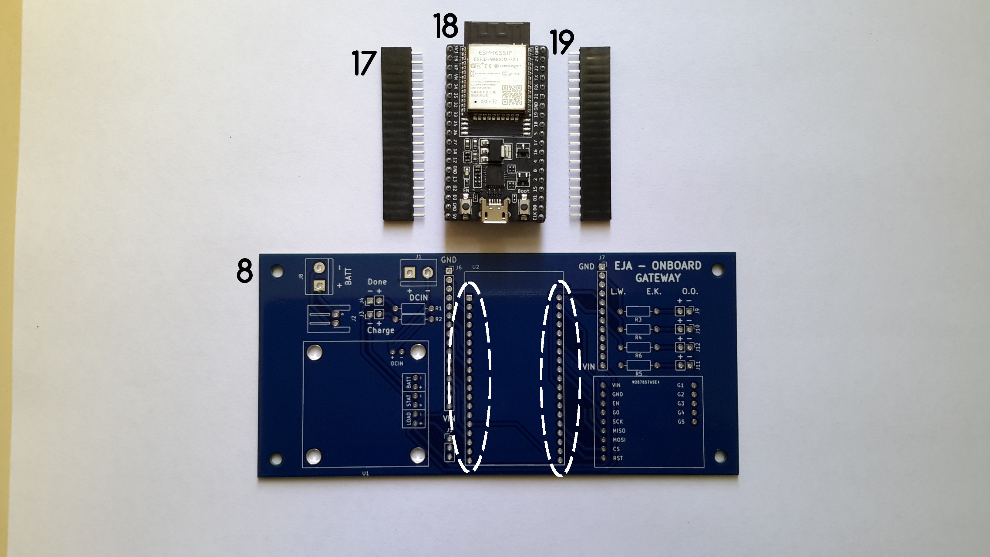
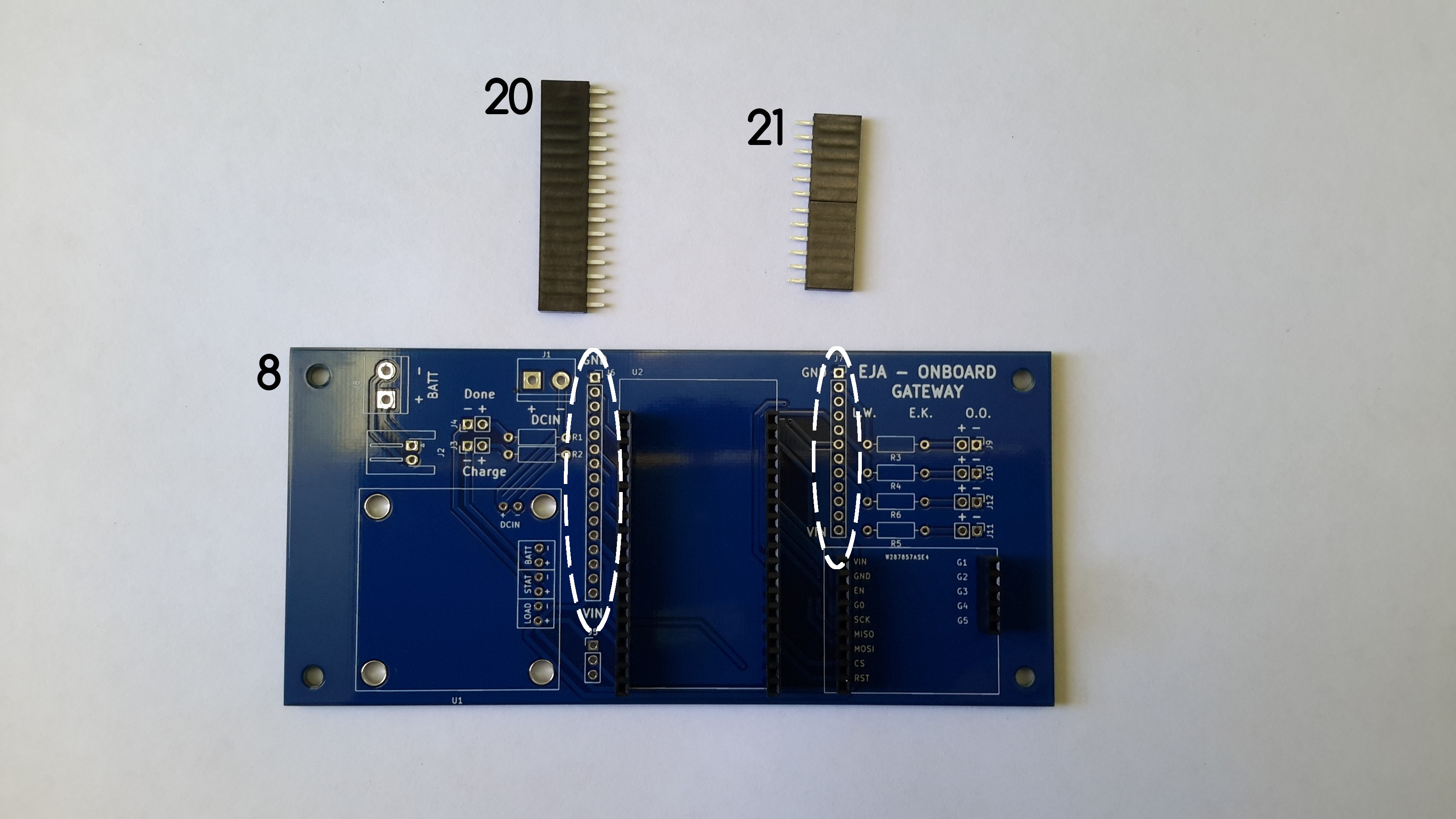
a. Solder the female headers 17 and 19 used to connect the ESP32-DEVKITC-32D to the Onboard Gateway V1.0.
![]()
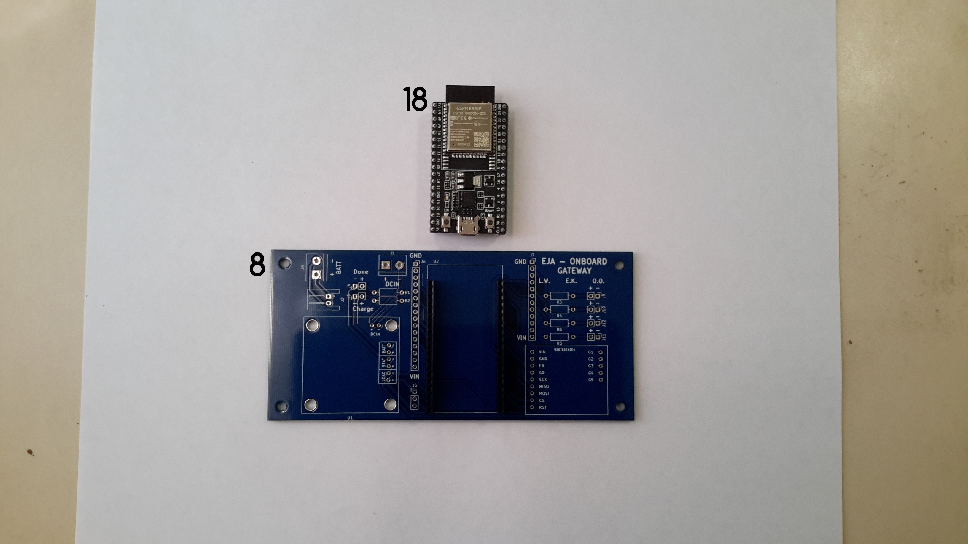
Once the female headers are soldered, the ESP32-DEVKITC-32D connects to the Onboard Gateway V1.0 through the headers.
![]()
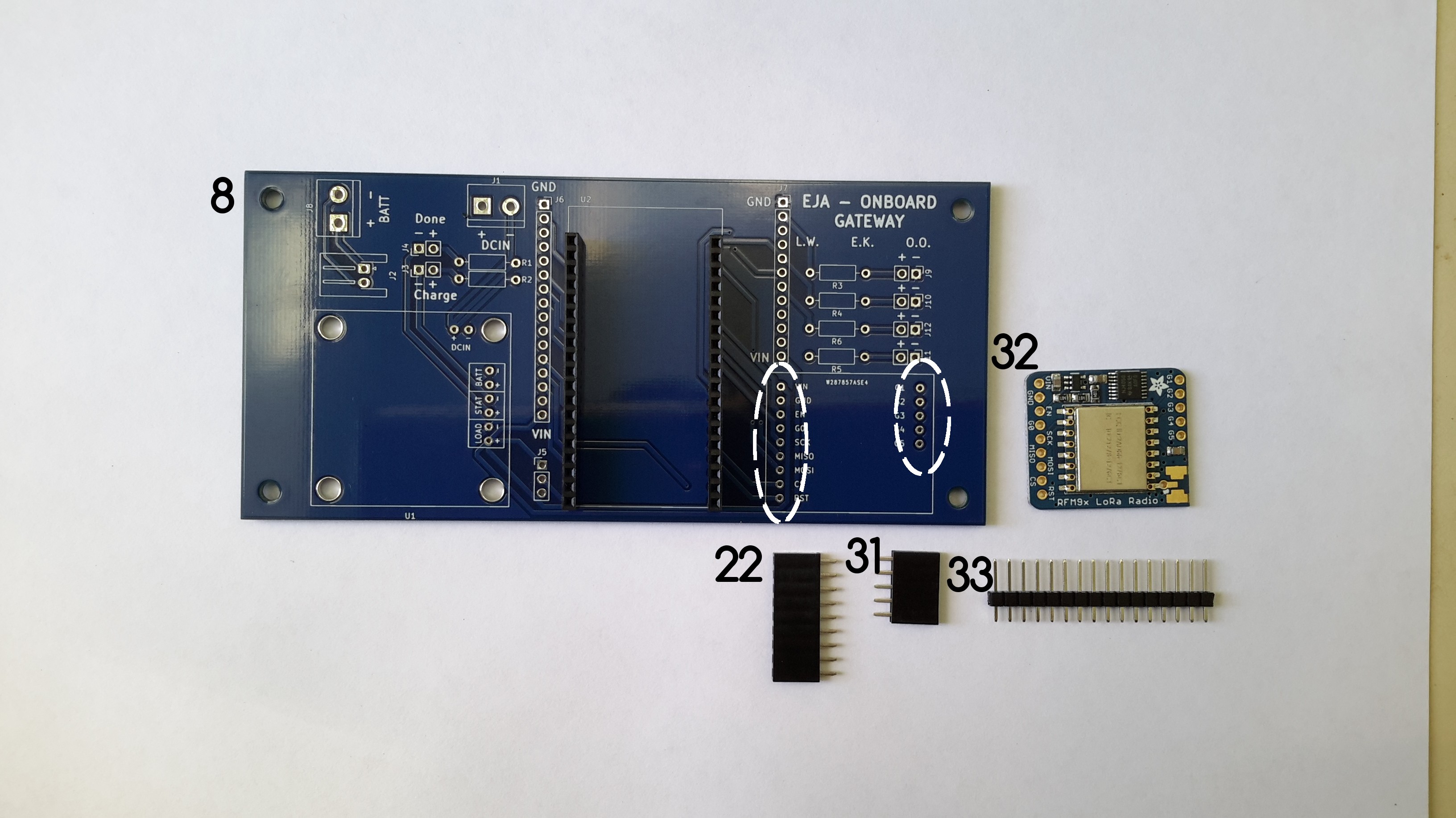
b. Solder the female headers 22 and 23 used to connect the RFM95W LoRa Radio to the Onboard Gateway V1.0.
![]()
c. Solder the male headers 33 to the RFM95W LoRa Radio. To do that it is necessary to cut a CONN HEADER VERT 9POS 2.54MM and a CONN HEADER VERT 5POS 2.54MM from the component 33. Once the female headers are soldered, the RFM95W LoRa Radio connects to the Onboard Gateway V1.0 through the headers.
![]()
d. Solder the female headers 20 and 21 to the Onboard Gateway V1.0.
![]()
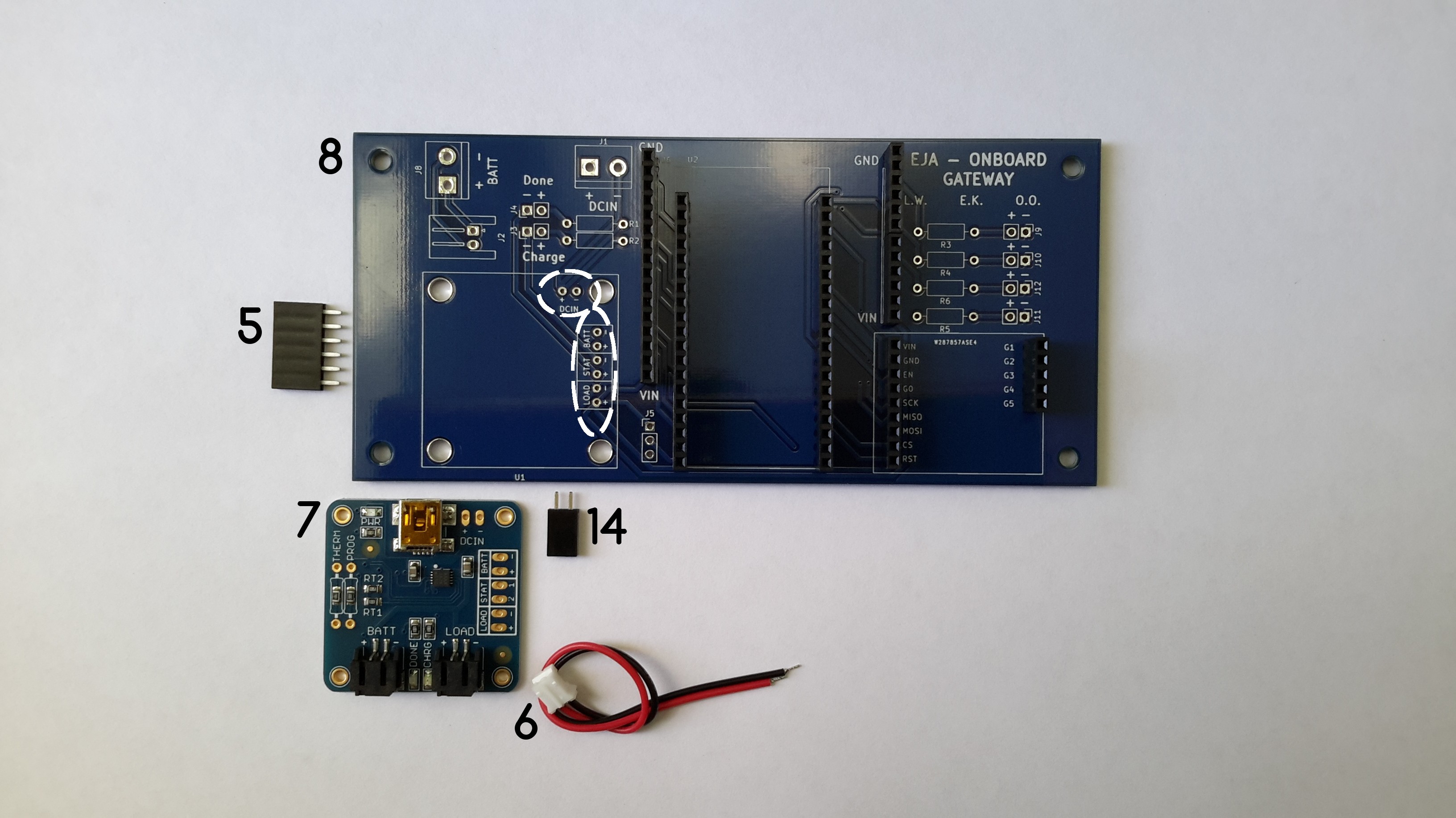
e. Solder the female headers 5 and 14, used to connect the USB LiIon/LiPoly charger to the Onboard Gateway V1.0. After that it is important to solder the male headers 9 and 13 to the USB LiIon/LiPoly charger.
![]()
The USB LiIon/LiPoly charger connects to the Onboard Gateway V1.0 through the headers.
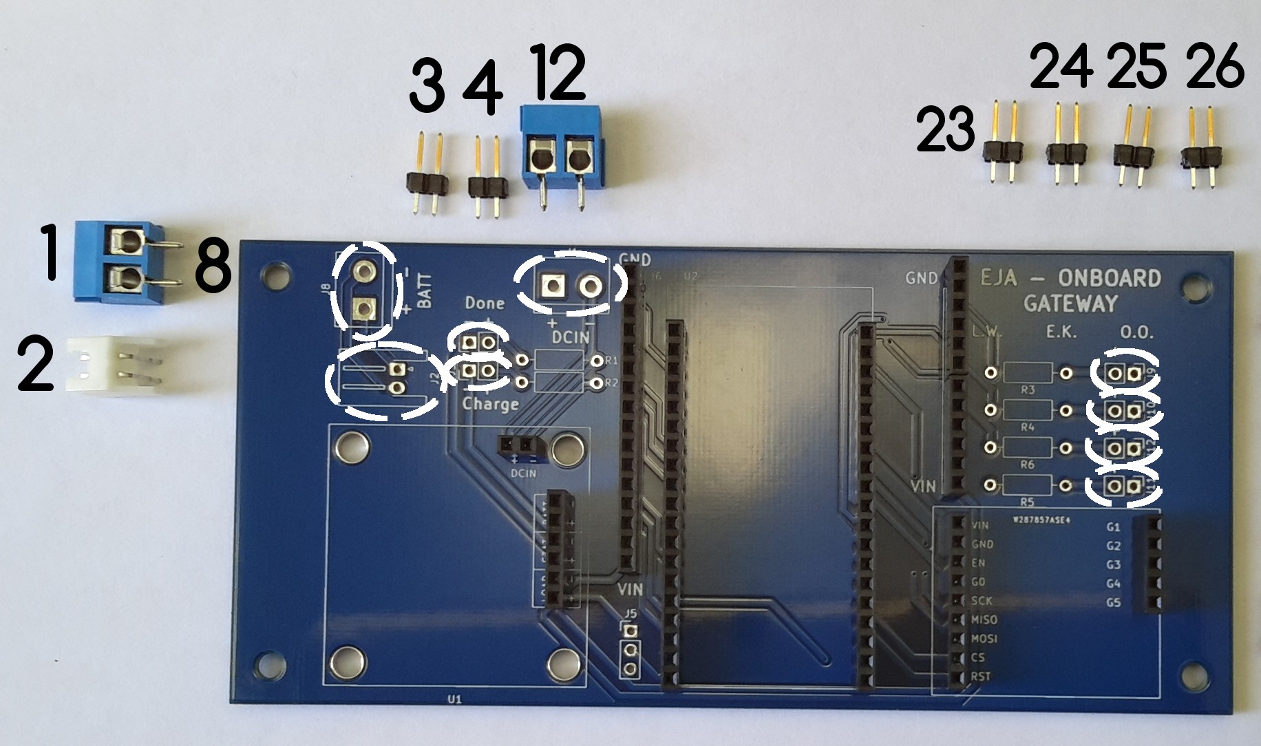
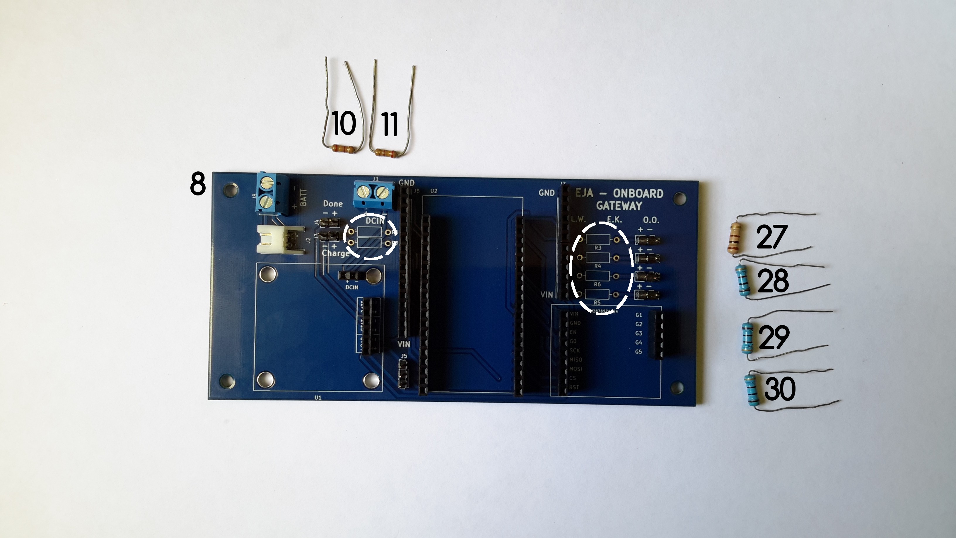
f. Solder the male headers and terminal block connectors.
Solder the male headers 3, 4, 23, 24, 25 and 25, used to connect the leds in the enclosure (through an additional cable). Solder the terminal blocks 1 and 12. Solder the 2POS Horizontal JST-XH connector (2)
![]()
Solder the male header 15.
![]()
g. Solder the resistors used for the leds.
![]()
2021 HDP Dream Team: EJA
Learn more about Team EJA's intelligent buoy, and how their solution will help the global fight against ghost gear.
 Using a motor with a limited power source means that current consumption needs to be monitored, especially for small robots. To make better estimations about how to optimize power use, it would be great to see how much current is being used by the servo. In this test we’ll use the