-
Maker Faire Pilsen
06/22/2021 at 07:54 • 0 commentsPilsen city, famous as the place where lager beer was invented, hosted a Maker Faire event in the beginning of June. L2Camera project was selected for this first after-the-lockdown event!
There were many makers showing their projects and crafts. My attention was caught by a project by Vaclav Mach (aka xx0x), the author of gbpxl (GameBoy Printer XL).
Vaclav showed talking wrist watches and a table clock. I liked these projects because they are done very thoroughly. He went even that far to reach out to Vaclav Knop, a Czech actor and director, whose voice was used for all railroad audio announcements across the country. Mr. Knop kindly agreed to record voice announcements again specially for the watch project.
The camera attracted attention and, surprisingly enough, I even got price quotes from the visitors!
-
Final touches
05/07/2021 at 07:47 • 0 commentsHaving spent decent time not only designing the camera, but also using it, I believe, I've developed the sense of control of it. Now I get photos exactly as I saw them. And the recent series would be an example.
I consider the design to be final. There were a couple of things I wanted to improve though.
There was a rectangular slot near the viewfinder - the legacy from Kiipix. A spirit level nicely fitted into the hole.

A spirit level fitted nicely to a slot near the viewfinder I designed the tripod socket of 3/8" size. I had two reasons for that. Firstly, I doubted that a 3D printed screw thread would be strong enough to hold the camera, and I chose the bigger thread size. Secondly, I had only a 3/8" tripod on hand to test the design.

A 1/4" to 3/8" metal adapter installed to the thread hole
Later I received comments that the 3/8" screw thread is inconvenient. I solved the problem by installing a metal adapter. The whole assembly works fine. -
Flash Mode
05/01/2021 at 19:08 • 2 commentsAn ideal scenario for party or reporter mode - is when one can (almost) forget about manual controls of the camera. The following setup does it.
What I particularly like about the L2Camera design is the ability to combine it with the existing photo gear. The picture below shows one of the L2Camera prototypes with an external handle and an automatic flash unit attached. A remote release cord is used for convenience.

L2Camera in flash/party/reporter mode
Lubitel shutter, thanks to its design, can be used with flash on any speed. Even a flash unit which is not powerful enough, combined with Instax high ISO film, together can easily give small apertures, like f/11, f/16. These apertures, in turn, provide large depth of field - and the photographer can be less worried about precise focusing.My recipe for indoor party/reporter mode with L2Camera and flash is:
- set shutter speed to 1/30 or 1/60
- use an automatic (computer) flash unit and set it to ISO 800
- set focusing distance to 2.8 m
- set aperture according to the distance and the settings of the flash (it should be around f/8.0 or f/11)
- use the frame viewfinder (as in the photo above)
- point and shoot!
With these settings L2Camera works almost the same way as conventional Instax camera: fixed focus, fixed aperture, frame viewfinder and automatic flash. -
Spring photos
05/01/2021 at 18:31 • 0 commentsWould like to share some photos I took with the P12 prototype.
The first five shots were taken on a sunny day. Instax film has ISO 800, according to the Sunny 16 rule I should use f/16 aperture and 1/800 speed. But Lubitel shutter provides speeds up to 1/250. Even if I use the smallest aperture provided by the lens f/22, then the speed should be 1/400, which is almost two times faster then the shutter offers. In other words, sensitivity of Instax film was too much for the lightning conditions. I decided to compensate excess of light by taking pictures against sun light. It gave an effect of +1EV or +2EV.

A hidden place near Petrin hill in Prague 
A steep path to the top of Petrin hill in Prague 
A wall under direct sunlight 
A tree in blossom 
Juicy spring grass
Below is a set of photos taken with monochrome Instax film on a cloudy day.
Swans on Vltava river in Prague 
An unexpected multi-exposure photo 
Prague under lockdown - no turists 
Prague under lockdown - empty visitor's center 
The Old Town Square - unusually empty -
Giving away camera bodies
04/14/2021 at 06:28 • 0 comments
L2Camera Early Prototypes
I have a bunch of camera body prototypes printed to validate the design of L2Camera. Would like to trade these for a coffee to those who are interested in building their own L2Camera. Buying an existing camera body saves your time, creates no additional plastic waste and frees up my place. Please have a look at my postings on Tindie: https://www.tindie.com/stores/2ndlife/ -
The project is grabbing attention worldwide
01/26/2021 at 12:22 • 0 commentsL2Camera project drew attention twice right before the Christmas 2020.

One of the camera prototypes had traveled half of the globe from Prague to Tokyo, where Keigo Moriyama, an Italian photographer living in Japan, made the first review of a L2Camera. In the review you can spot the same camera body that was printed and assembled in the course of writing these log entries.
Keigo has kindly shared with the project the photos he took during the review session. Here they are.
The first scene at 3:40

The second scene at 3:48

The third scene at 3:58

The fourth scene at 4:06

The fifth scene at 4:14

The sixth scene at 4:22

The seventh scene at 4:30

The eighth scene at 4:39

The ninth scene at 4:47

The tenth scene at 4:56

Also, Keigo provided technical feedback. He suggests adding a cold shoe mount and switching from 3/8" tripod thread to 1/4". According to Keigo, a cold shoe could carry additional equipment like a like meter, and 1/4" tripods are more common now.
The project took part in Maker Faire Rome 2020 virtual event. It was both interesting and challenging to show case the project through a virtual stand while sitting at home in reality.

-
Assembling the camera body
01/19/2021 at 12:32 • 0 commentsTo assemble a L2Camera body the following components and tools are needed:
- a front panel, adjusted to the viewfinder lens
- a main body part
- a tripod mount
- strong glue for PLA, e.g. "super glue", "methacrylate", etc
- a wire cutters
- an utility knife
- a piece of PLA filament

First step - index pins
There three round holes on the rear surface of the front panel and three their counterparts on the front surface of the main part. Check that filament goes easily into the holes. If not, adjust the holes with a sharp an narrow tool. Then glue in PLA pieces into holes of the main part, and cut filament 2 mm above the surface. You got register pins to facilitate alignment of the camera body parts. Now put the main body part on a horizontal surface with the pins on top and then put the front panel above the main part, align both parts with the register pins, join the parts together and check that there is not gap between them. If there is a gap, shorten the pins and check again.


Second step - gluing the parts together
Now put again the main body part on a horizontal surface with the pins on top. There are four rectangular pads on the main body part and four their counterparts on the front panel. Apply glue to the pads on the main body part. If you printed the model with brims, them apply some glue to the brims at the edge of camera body - that will create a better looking seam. Now put the front panel above the main part, align both parts with the register pins - start with the pin near the main lens hole and then proceed with the pins near the viewfinder lens hole. Join the parts together and apply some force for approx. 10 seconds to form a tight joint.

Third step - post-gluing finishing
If you printed with brims, remove them with an utility knife.
 Prepare the tripod mount part - remove the brim if you printed with brims - then slide in the socket part into the hole at the bottom of the main body.


The result


-
Adjusting front panel to the viewing lens
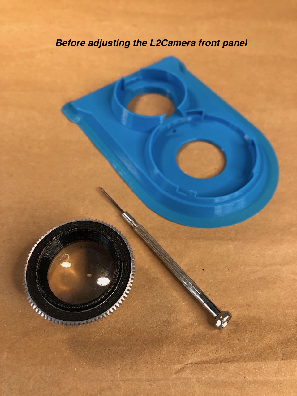
01/19/2021 at 12:31 • 0 commentsL2Camera front panel is designed to be adjusted to the particular viewfinder lens of the donor Lubitel camera. For that reason, the 3D model has the screw thread which is tighter than necessary. The adjustment procedure requires you to widen the thread by applying heat to it.
![]()
You need:- a L2Camera front panel printed with PLA
- a Lubitel viewfinder lens (the top one)
- a 1.0 mm flat screwdriver
- a source of warm air (approx. 50C/120F) - a hairdryer works best
![]()
Steps:
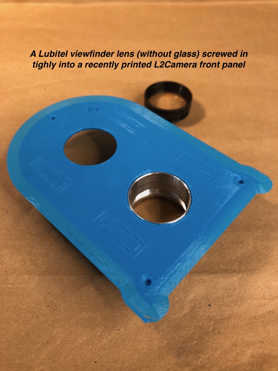
- check that the lens screws in into the front panel tightly, if not - if it goes loosely - please report to me.
- unscrew and release the lens block (glass) from lens rim by undoing the stopping screw on the rim - you'll get the aluminum lens rim without glass
- screw in the rim into the front panel as deep as it possible, but don't apply to much force
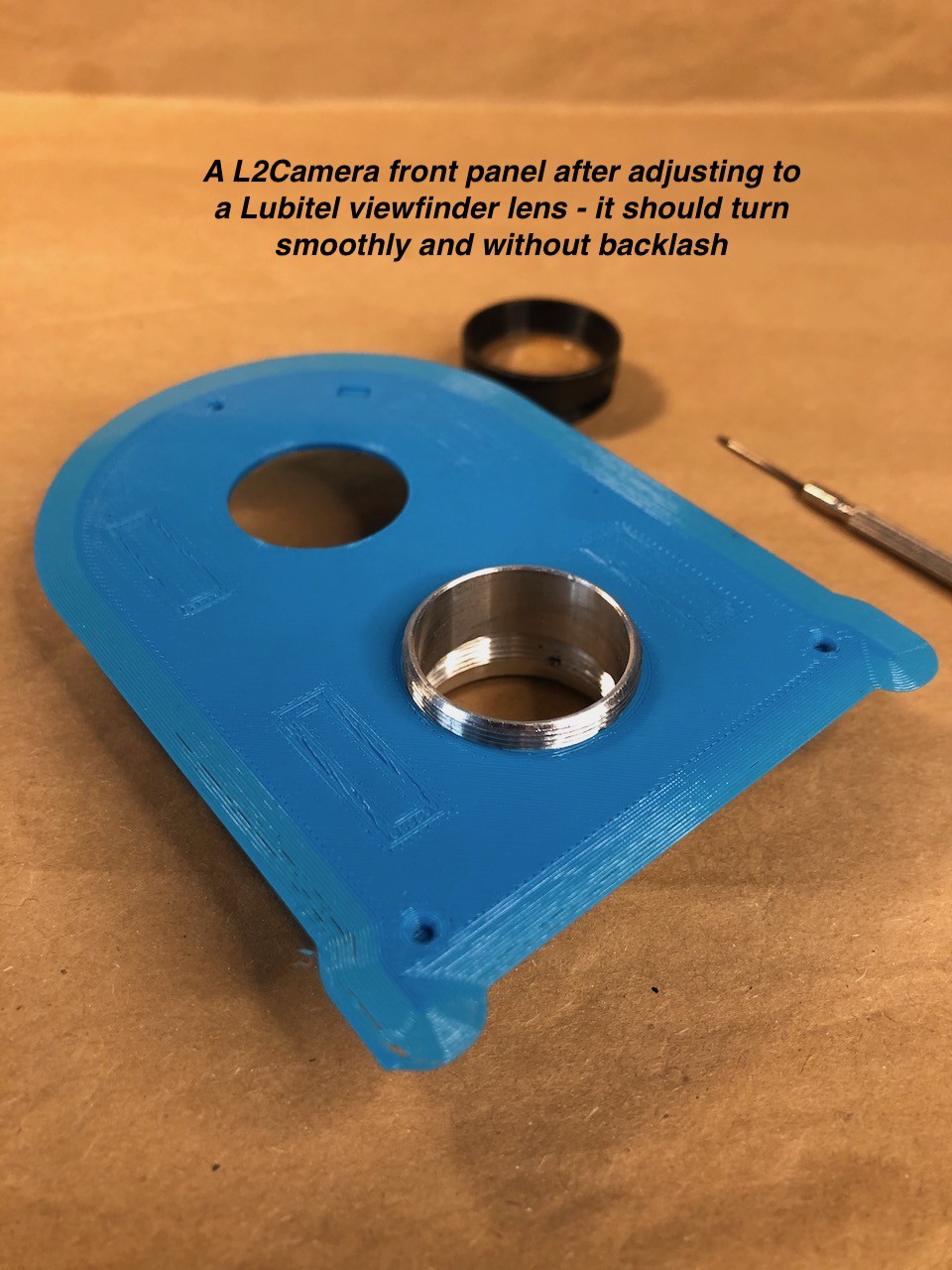
- warm up the rim screwed in into the front panel with warm air by applying it to the inner surface of the rim only. Try not no heat other surfaces of the panel
- screw in the rim a bit further and let the whole assemble to cool down
- check if the rim screws in and out completely, smoothly and without backlash; if it doesn't then repeat the step 3
- put the lens block back into the rim and secure it with the stopping screw.
![]()
-
Printing the camera body
01/14/2021 at 16:44 • 0 commentsAfter releasing the 3D model, I'd like to share my recommendations on printing the camera body. Before printing, please consider my notes regarding printer selection.
![]()
The 3D model is designed to be printed with:- PLA filament (please refer to my considerations on filament)
- a 0.4 mm nozzle and 0.2 mm layer height
- two perimeters, no supports
- the infill value of 5% (it's enough)
- any kind of infill pattern, please consider Gyroid
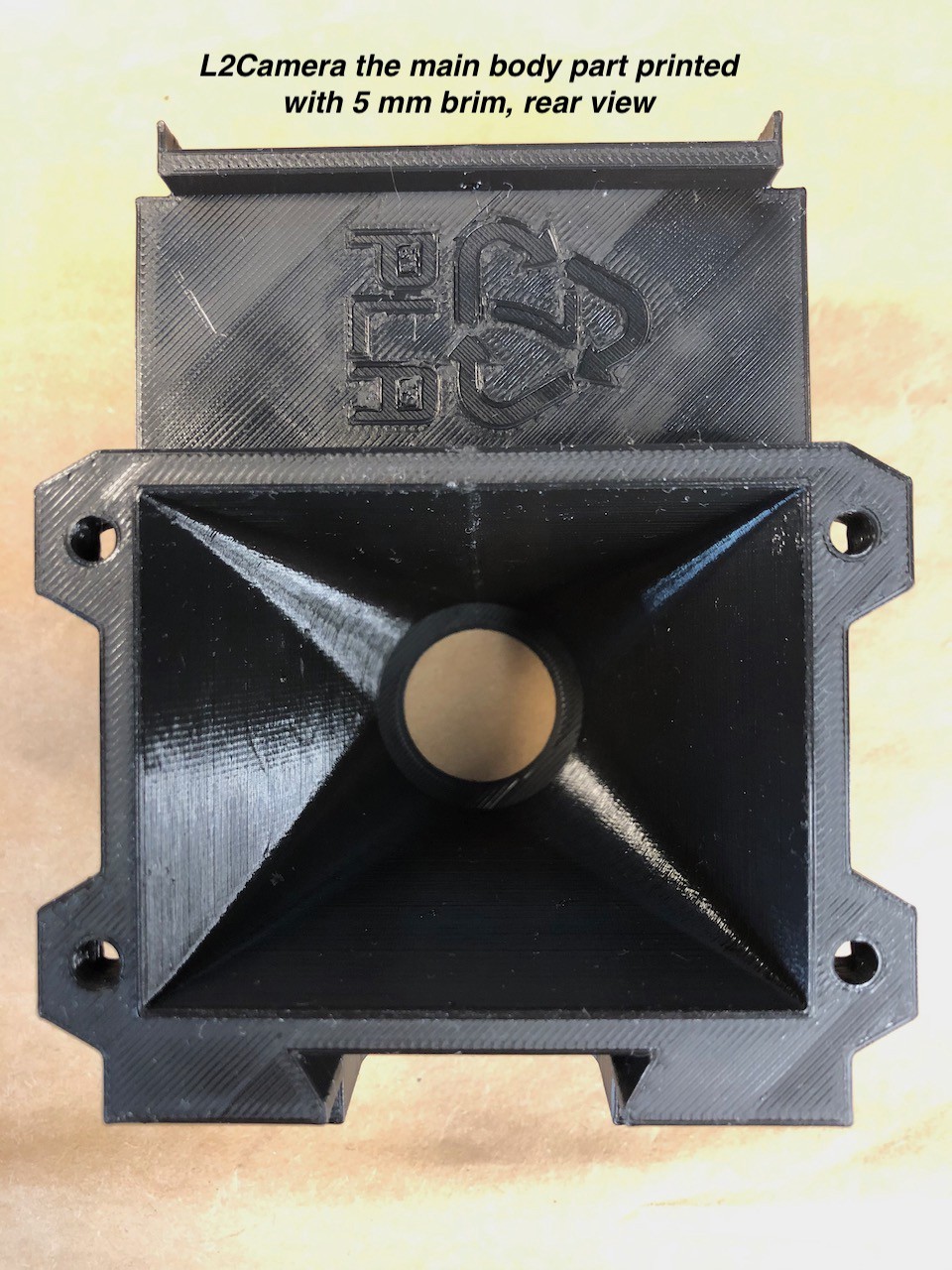
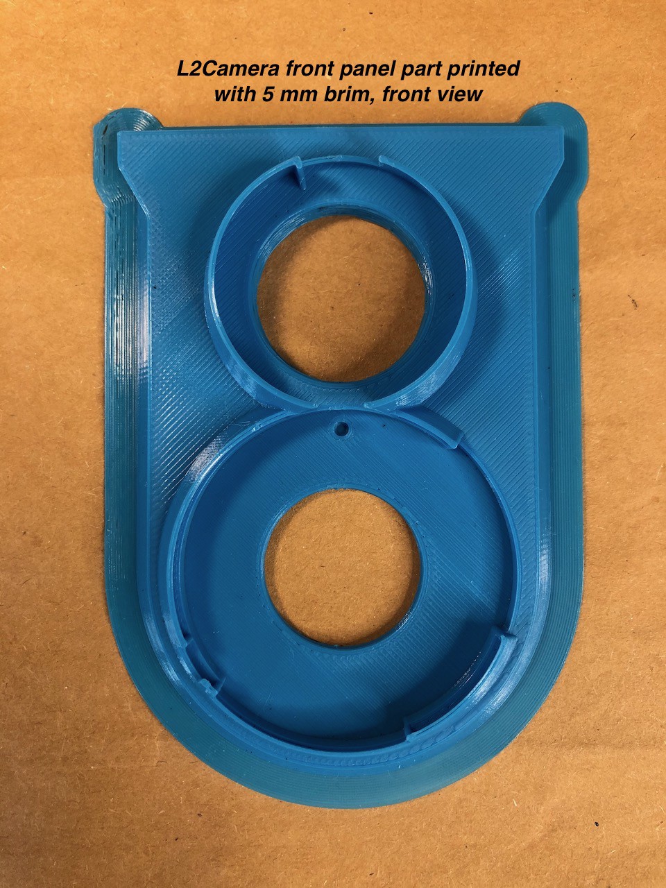
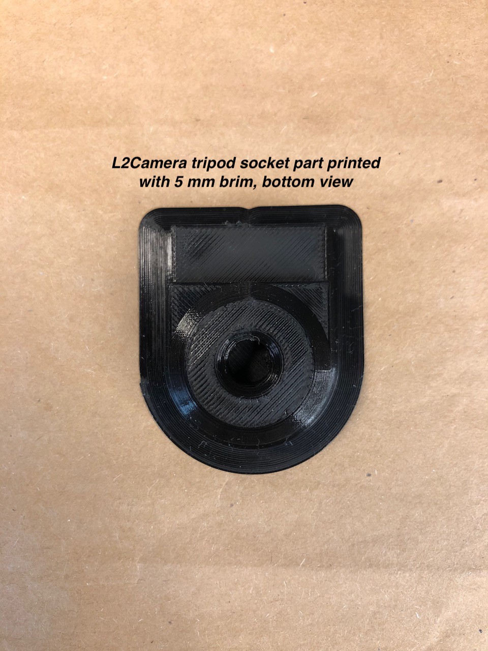
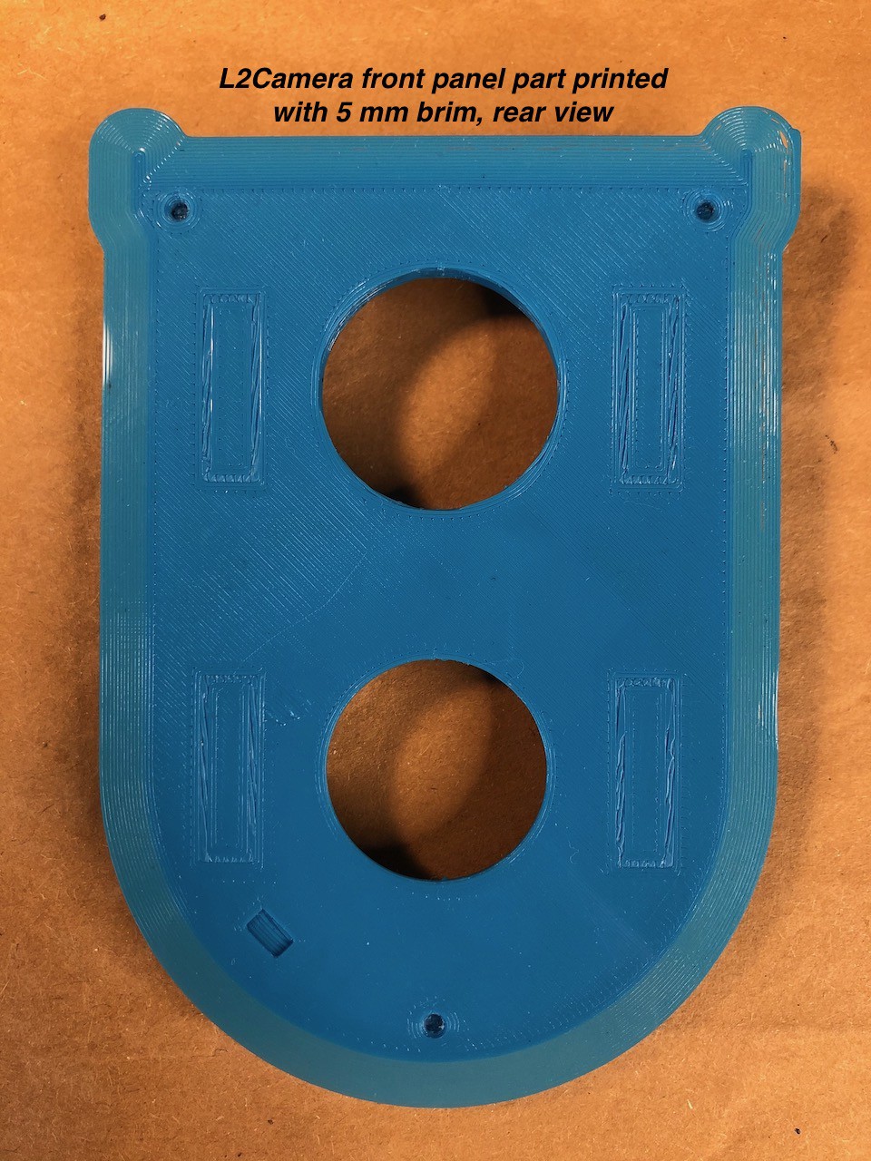
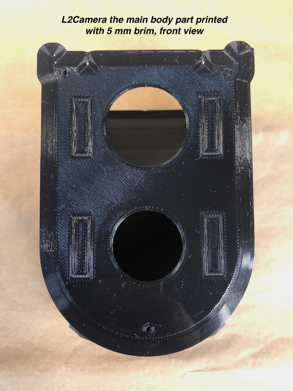
If your printer doesn't have PEI surface, I highly recommend to add a 5 mm brim to increase adhesion of plastic and prevent warping.
The STL file contains the following four parts:
- the front panel
- the camera body itself
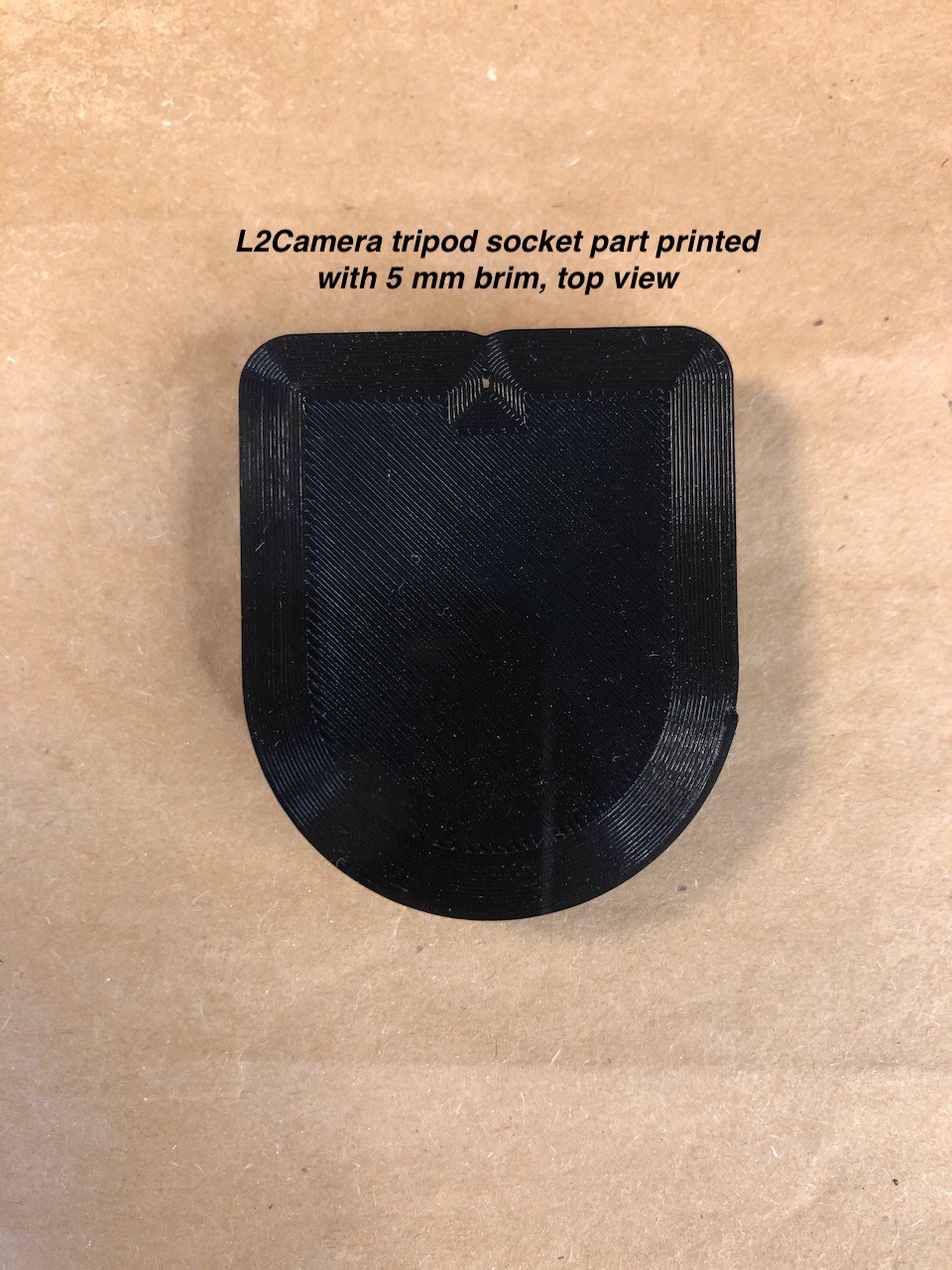
- the tripod socket
- the light-blocking insert, optional
I recommend to print the parts in the same sequence. Print the front panel and check that the Lubitel's viewing lens screws in tightly. It can be even very tight - that is expected, that is by design. Later, during assembling, this issue will be fixed and the lens will match the thread perfectly. If the lens fits loosely, please report this case to me.
Next, print the camera body and the tripod socket. Print the last part, the light-blocking insert, only if the previous parts are not opaque enough. You can print the insert with any PLA filament and paint its internal surface with 3-5 layers of black acrylic water-based paint.
![]()
![]()
![]()
![]()
![]()
![]()
-
Releasing the L2Camera 3D model
12/10/2020 at 19:35 • 0 commentsAfter half a year of prototyping the project came to a point, when it's ready to be shared with a broader audience. The STL file with camera body part is available now!
![]()
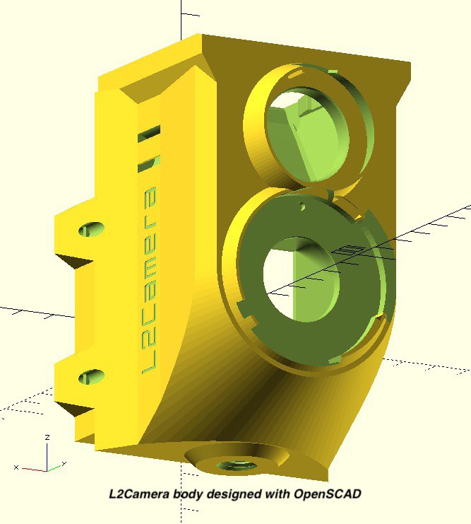
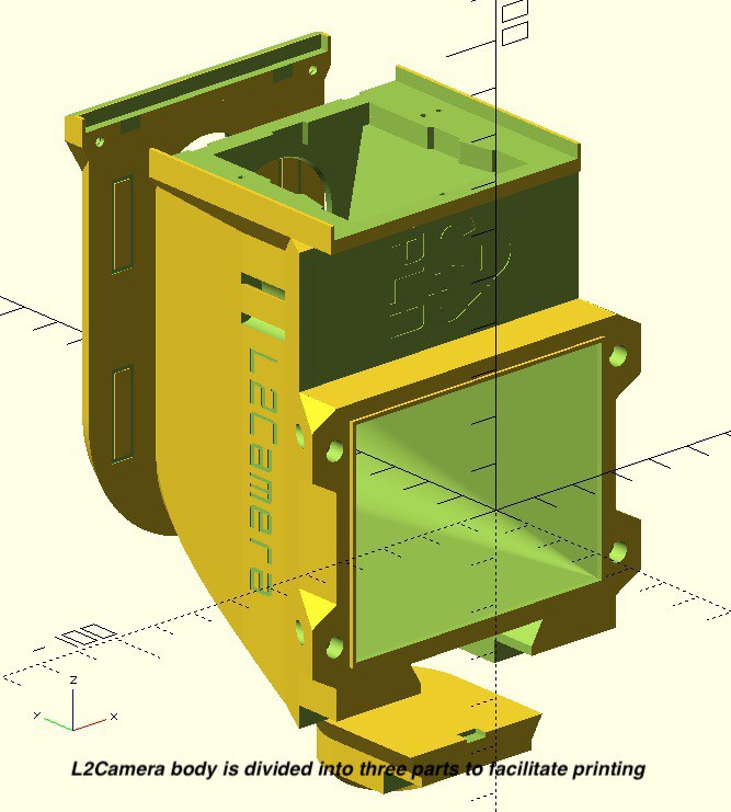
I used OpenSCAD software to design the camera body. I made the model many parameters to have it adjustable.
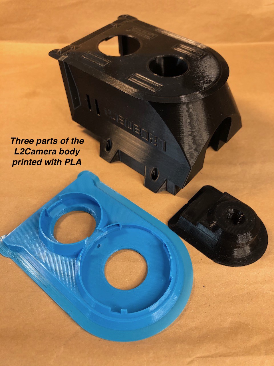
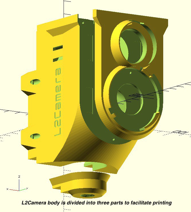
To facilitate printing I divided the model into three parts: the front panel, the middle part and the tripod socket.
![]()
The rear panel contains a recycling sign identifying filament.
![]()


 Prepare the tripod mount part - remove the brim if you printed with brims - then slide in the socket part into the hole at the bottom of the main body.