It has been a while since I had time to work on the TX8 but the past two days I managed to squeeze a few hours in.
The last time working on the system I got the new TMS9929A devices in and they all seemed to be working. At the time I did not have a display connected so I assumed that when I could read and write data properly to the VRAM that the VDP was working. Unfortunately that was not the case. After finally building a SCART RGB cable for the system I could see that the monitor was getting a proper sync but the displayed pattern did not make any sense at all.
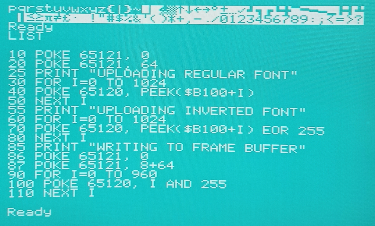
After playing around (using BASIC) I noticed that the display memory seemed non linear. When writing a sequence of data to the display area I could see on the display that different segments of the display getting updated in a non linear way. Obviously that was not what I expected.
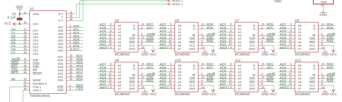
I went back to the schematic and studied the VDP section and actually had to study it for a while before I caught my mistake. Can you spot the error ?
The data sheet is extremely clear on how to connect the VRAM and I missed it. Look at the AD0 to AD7 pins of the VDP. I have mistakenly reversed the naming. This was probably done very early on the design process and I never caught it even though I spent months mulling over the schematic.
Bah, never mind, mistakes were made but it is a rather complex design with a lot of different buses and signals.
After fixing this error (cutting and replacing traces) the system started up as expected.
The BASIC that I am running is a 65C02 enhanced version of ehBasic. ehBasic was written by Lee Davison and is a derivative of Microsoft BASIC. It is a bit slow and I wold have preferred an integer BASIC but it has proven instrumental in debugging the hardware.
In the next update I will talk a little about implementing the keyboard driver.
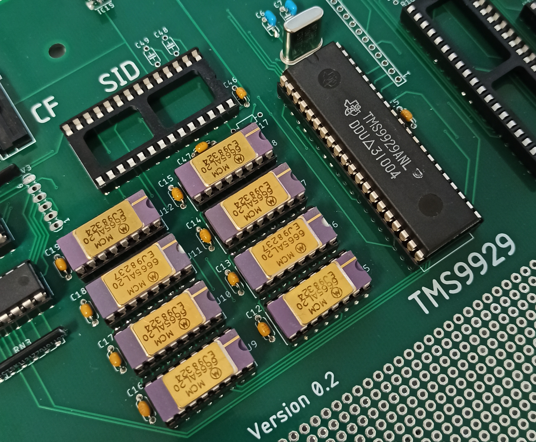
So the new TMS9929ANL chips finally arrived. For those of you that have been following me on Instagram you will know that the first chips that I bought on eBay turned out to be fake ones. This time I turned to a few different sources to ensure that I at least got a few working units. The first devices to arrive was from a contact that I have in Shenzhen which I also use professionally to source parts that are difficult to get here in the west. He actually got me 10 samples for $0.85 which is a very fair price for these devices.
Anyway, a bit skeptic I started to do the acetone test.... All good, none of the paint came off. While doing this I also noticed a small molded Texas Instruments logotype in one of the blank circles on the top of the device which made me feel even better. You can se it in picture if you look closely.
Now for the real test. Would I get the 10.73 MHz oscillator running ? (drum-roll)
YES !! it works. A clean oscillator signal is present at pin 40 (If you want to measure this signal accurately do not measure the signal on pin 39. The capacitance of the probe will affect the oscillator and show you an incorrect frequency). The frequency is coming in a bit high at 10.739 but this is easily correct by adjusting C6 and C7. A trimmer cap would have been handy here but it won't take to long to tune the values. Second stage of the testing was to install the DRAM's and make sure that I can write data and read it back properly. So I wrote a short test program that wrote a test pattern to the memory and verified that it would read back properly. I let the program run for a few hours and no errors were found during this time. I also verified all the setup and hold time parameters with an oscilloscope, just to put my mind at ease. The VDP seem to perform significantly better than specified which means the timing margins are very good.
The DRAM's that I use are new old stock that I have been holding on to for decades. During the summer of 1984 I was working for a company assembling cardiographic measuring machines. These machines had a big CPU board with an i8085 CPU and a bucket load of TTL's and IO devices. My job was to test the boards and install them into the machines. All main boards that failed tests were scrapped, no repairs were done. Every board had 128Kbyte (16 pcs) of these MCM6665AL20 and I was allowed to strip the DRAMs from these boards and take home. I have kept them all of these years knowing it would come in handy some day =).
Anyway, the conclusion for today is that the TMS9929ANL and the DRAM circuitry seem to be doing its thing. I haven't tested connecting a monitor to it yet so the verdict is still out.
The next step is to install the RGB modulator and start testing that part of the circuitry so stay tuned.
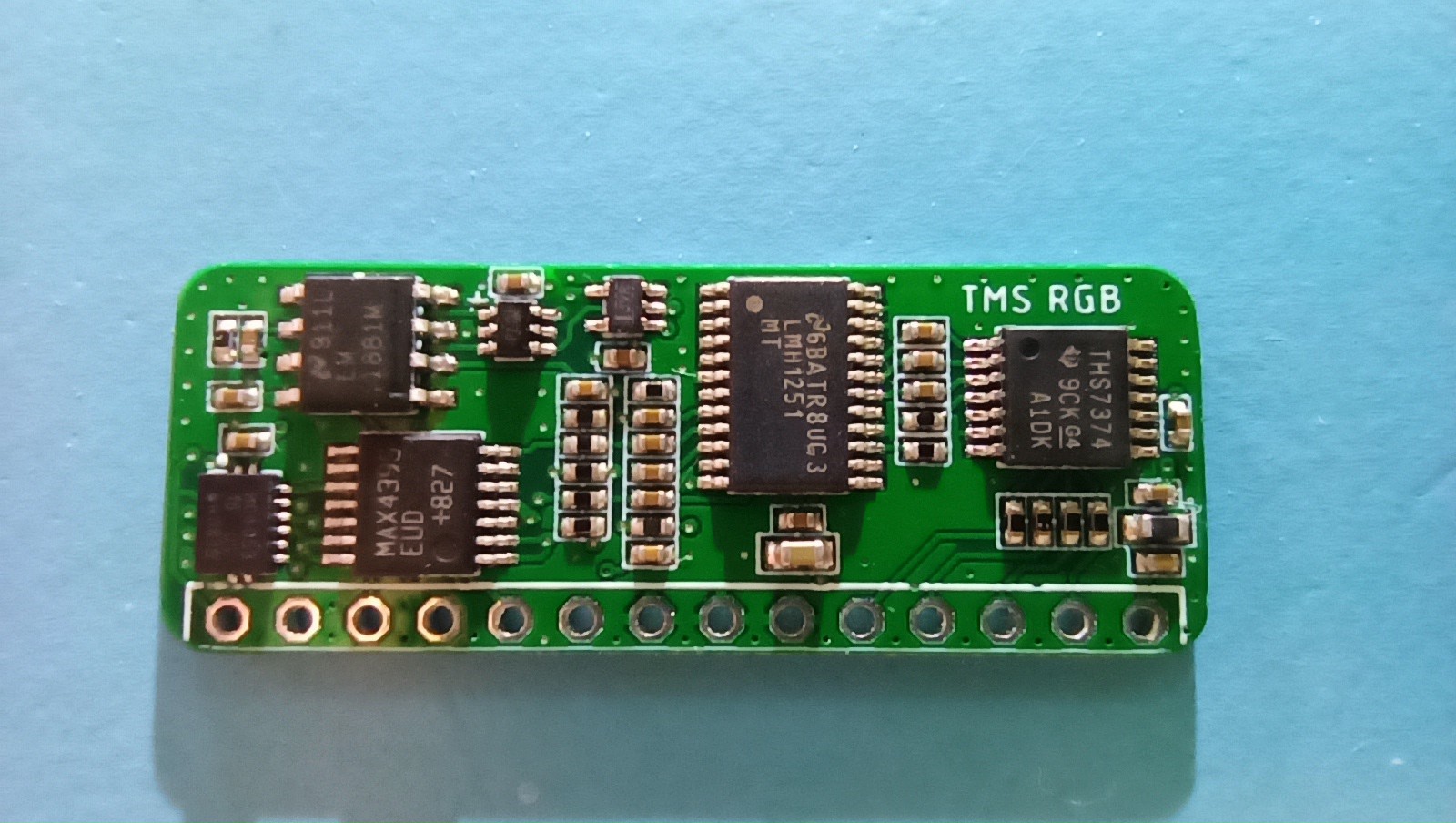
The first prototype samples of the TMS-RGB module for the TMS9929A were finished today. and they look great. Now all I need is the actual TMS9929A devices to start testing everything out.
Looks great doesn't it.
I take no credit for the actual design, it was done by Nicholas Pigdeon (@npigdeon) and his story is available on http://tms-rgb.com. I only re did the layout using smaller components with the aim to make it a very small module. I could probably have shaved off a few mm's more from it but I was satisfied with the result.
Testing will start as soon as I have a 9929A running in the TX8 computer.
The processor section, keyboard controller, Compact Flash and the UART sections of the board have been built and tested. A few small minor bugs were found and corrected on the PCB, nothing major so far. All electrical parameters such as setup times, hold times etc have been verified so I know that the design is good.
I opted for PLD's for all the select logic so I am able to do pretty cool stuff with it. For instance, all IO is injected into ROM space at $FE00 and the IO page is 256 byte long. Here I can assign chip selects to any address on a 16 byte boundary which makes the IO area almost invisible.,
I am currently running a version of the NoICE debugger fw on the board which makes it super easy to download new software and single step the program on my windows computer.
The first real snag that hit me was that the TMS9929 chips that I purchased were fake. Very easy to detect to. Just had to rub the devices with a little acetone and the paint came right off. very annoying. Got my money back and have purchased new chips from a supplier that was recommended to me. But it takes forever for them to arrive so in the mean time I am doing some software development instead.
The main reason for installing the compact flash card on the PCB was that I wanted to write a simple file system for 65C02, so this is what I am doing right now.
 Second stage of the testing was to install the DRAM's and make sure that I can write data and read it back properly. So I wrote a short test program that wrote a test pattern to the memory and verified that it would read back properly. I let the program run for a few hours and no errors were found during this time. I also verified all the setup and hold time parameters with an oscilloscope, just to put my mind at ease. The VDP seem to perform significantly better than specified which means the timing margins are very good.